Page is loading ...

6245 State Rd. Telephone 215-624-4800
Philadelphia, PA 800-344-4802
19135-2996 FAX: 215-624-6966
www.insingermachine.com
TECHNICAL MANUAL
FOR
FLIGHT TYPE
DISHWASHER
MODELS
CLIPPER
MASTER

FLIGHT TYPE DISHMACHINES
Clipper/Master
Table of Contents
Part 1 - Technical Information
* Introduction
* Catalogue Cut-sheet and Installation Drawing
* Warranty
Part 2 - Installation and Operation Instructions
* Section A, Installation Instructions
* Section B, Operation and Cleaning Instructions
Part 3 - Maintenance and Repair Procedures
* Section A, Maintenance and Repair Procedures
* Basic Service Guide
Part 4 - Electrical Schematics and Replacement Parts
* Machine Wiring Diagrams
* Control Panel Layout and Component Drawing
* Electric Blower Dryer Wiring Diagram
* Electric Blower Dryer Control Panel Layout & Control Panel Layout
* Electric Booster Wiring Diagram
Part 5 - Replacement Parts
* Overall Assembly Drawing for:
* Clipper
* Master
* Drain Assembly
* Motor Assemblies
* Conveyor Overload Shutoff Mechanism Assembly
* Auto Tank Fill Assembly
* Level Float Installation
* Final Rinse Assembly
* Curtain, Rods Assembly
* Steam Injectors, Steam Coils and Steam Booster Assembly's
* Electric Booster Assembly
* Photoelectric Eye Installation
* Rack Section Details
* Cold Water Thermostat Piping
* Blower Dryer Details
cm \mnl\mnlflt.doc rlsd: 5/91

100 Years of Service
DESIGN
Automatic Conveyor, flight type three
tank dishwasher with recirculating
prewash, wash and rinse; and fresh
water final rinse. Capacity is 10,800
dishes per hour, with a conveyor
speed of 8.3 ft. per minute. Designed
for left or right hand conveyor travel,
as specified.
STANDARD EQUIPMENT
• Tank Heat: 60 KW Electric
Immersion Heater or Steam
Injector
• Capillary Thermometers for Pre-
Wash, Wash and Rinse
• In-Line Thermometer for Final
Rinse
• Vacuum Breaker
•Manifold Cleanout Brush
•Inspection Doors
•S/S Frame with S/S Legs
•Automatic Tank Fill
•Low Water Protection
•Detergent Connection Provision
•Top Mounted Control Panel
(NEMA 12)
•Steam Booster
•Simplified Scrap Screen Design
•Door Safety Switches
•End Cowls with Vent and
Adjustable Damper Controls
•Standard Frame Drip Proof
Motors
•Conveyor Reversing Switch
•Choice of Poly or S/S Belt with
Removable Rack Sections
•Conveyor Safety Step Bar
•Override Switch for De-liming
OPTIONAL ACCESSORY
EQUIPMENT
? Stainless Steel Steam Coil
Tank Heat
? Pressure Reduction Valve and
Line Strainer
? Electric Booster
? Security Package
? Totally Enclosed Motors
? S/S Front Enclosure Panel
? S/S Panels All Sides
? Insulated Hood and Doors
6245 State Road
Philadelphia PA 19135-2996
215/624-4800 215/624-6966 FAX
800/344-4802
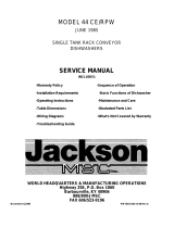
Clipper RC
AUTOMATIC THREE TANK
RACKLESS CONVEYOR
DISHWASHER
NOTES:
Machine Company

100 Years of Service Clipper RC
Note: For all rough in connections see Installation and Layout Detail Drawing.
SPECIFICATIONS
CONSTRUCTION—Hood and tank constructed of 16 gauge 18-8 type 304 S/S. Hood unit of all welded seamless construction. S/S frame and
legs. All internal castings are non-corrosive nickel alloy, bronze or S/S investment.
DOORS—Three extra large die formed 18-8 type 304 S/S from inspection doors riding in all S/S channels. A triple ply leading edge on the door
channels made of S/S with no plastic or nylon sleeves or liners used. Two intermediate S/S door-safety stops on the door. CONVEYOR—
Polypropylene or S/S rack sections on S/S belt with Hi-D rollers and removable rack sections. Conveyor drive system includes targe speed reducer
with cut gears operating in oil bath and with frictionless, trouble-free clutch system. Dishware conveyed automatically through all washing and
rinsing systems powered by an independent 1/2 HP conveyor motor. A stop bar sits at the end of the unload section. This will shut off the conveyor
if any ware hits the bar.
PUMPS —Centrifugal type "packless" pump with a brass petcock drain. Construction includes ceramic seal and a balanced cast impeller on a
precision ground stainless steel shaft. All working parts mounted as an assembly and removable as a unit without disturbing pump housing. Two 2
HP motors, 1725 RPM -wash and rinse; and 1.5 HP, 1725 RPM - pre-wash: standard frame, horizontal C-faced. drip proof, squirrel-cage, induction
run type, 60 cycle, internally cooled with ball-bearing construction.
CONTROLS—Top-mounted control cabinet, NEMA 12 rated with heat insulation provided between hood and control cabinet, housing motor
controls and overload protection, transformer, contactors and all dishwasher integral controls. All controls safe low voltage 24 VAC.
ENERGY SAVER—Electric photo eye automatically operates the final rinse solenoid only when ware passes, saving water and energy. The photo
eye also activates an adjustable timer control. If no ware passes during the set time, the machine shuts down.
SPRAY SYSTEM—Pre-Wash, wash and rinse spray arms made of 18-8 type 304 stainless steel schedule 40 pipe. Spray assemblies removable
without the use of tools.
Pre-Wash-Upper and lower manifolds. One manifold above with 3 power wash arms designed with 7, 6, and 7 high pressure action cleansing slots
and one manifold below with 3 power wash arms each designed with 6 high pressure action cleansing slots. The slots precision milled for water
control producing a fan spray. Wash arms are fillet welded to the S/S manifold.
Wash-Upper and lower manifolds. One manifold above with 3 power wash arms designed with 7, 6, and 7 high pressure action cleansing slots and
one manifold below with 3 power wash arms each designed with 6 high pressure action cleansing slots. The slots precision milled for water control
producing a fan spray. Wash arms are fillet welded to the S/S manifold.
Rinse-Upper and lower manifolds. One manifold above with 3 power rinse arms designed with 7. 6, and 7 high pressure action cleansing slots and
one manifold below with 3 power rinse arms each designed with 6 high pressure action cleansing slots. The slots precision milted for water control
producing a fan spray. Rinse arms are fillet welded to the S/S manifold.
Final Rinse-eight nozzle assemblies above and four nozzles below threaded into S/S schedule 40 pipes. Nozzle assemblies produce a cone spray
reducing water consumption, maximizing heat retention.
DRAlN-Drain valves externally controlled. Overflow assembly with skimmer cap is removable without use of tools for drain line inspection.
Heaters protected by low water level controls.
Capacity per hour
Tank capacity
Motor size
Electric usage
Steam consumption
Final rinse peak
at 20 psi min. flow at 20 psi min.
1.5 hp (pre-wash)
182 lbs./hr. tank
10,800 dishes 600-1,200
meals
24 gals. (pre-wash) 27
gals. (wash) 30
gals.
(rinse)
2 hp (wash) 2 hp
(rinse) 1/2 hp
(conveyor)
50 kw wash tank 39
kw booster 40°rise
(2)
38 kw boosters
70°rise
138 Ibs./hr. rem.
booster 40°rise 241
Ibs./hr. rem. booster
70°rise
6.5 gals./min.
Final rinse
consumption
Exhaust hood Peak rate
at 20 psi per minute
requirement drain flow
389
gals./hr.
500 CFM Load
1000 CFM Unload 23 gals./min.
Shipping weight
3250 lbs.
Current Draw Steam
Electric
Amps w/o
booster
208/3/60……………………..23……………………161
230/1/60……………………..n/a……………………n/a
230/3/60……………………..23……………………146
380/3/60……………………..18…………………….94
460/3/60……………………..13…………………….73
LEFT TO RIGHT FEED


Master RC
AUTOMATIC THREE TANK
BACKLESS CONVEYOR
DISHWASHER
DESIGN
Automatic Conveyor, flight type three tank
dishwasher with recirculating prewash, and
rinse; and fresh water final se. Capacity is
13,000 dishes per hour, with a conveyor
speed of 10.4 ft. per minute. Designed for left
or right hand conveyor travel, as specified.
STANDARD EQUIPMENT
• Tank Heat 50 KW Electric Immersion
Heater or Steam Injector
• Capillary Thermometers for Pre-Wash,
Wash and Rinse
• in-Line Thermometer for Final Rinse
• Vacuum Breaker
OPTIONAL ACCESSORY
EQUIPMENT
Stainless Steel Steam Coil Tank Heat
Pressure Reduction Valve and Line
Strainer
Electric Booster
Security Package
S/S Front Enclosure Panel
S/S Panels All Sides
Insulated Hood and Doors
Totally Enclosed Motors
• Manifold Cleanout Brush
• Inspection Doors
• S/S Frame with S/S Legs
• Automatic Tank Fill
• Low Water Protection
• Detergent Connection Provision
• Top Mounted Control Panel (NEMA 12)
• Steam Booster
• Simplified Scrap Screen Design
• Door Safety Switches
• End Cowls with Vent and Adjustable
Damper Controls
• Standard Frame Drip Proof Motors
• Conveyor Reversing Switch
• Choice of Poly or S/S Belt with
Removable Rack Sections
• Conveyor Safety Stop Bar
• Override switch for de-liminq
6245 State Road Philadelphia PA
19135-2996 215/624-4800 215/624-
6966 FAX
800/344-4802

LEFT TO RIGHT FEED
Note: For all rough in connections see Installation and Layout Detail Drawing.
SPECIFICATIONS
CONSTRUCTION—Hood and tank constructed of 16 gauge 18-8 type 304 S/S. Hood unit of all welded seamless construction.
S/S frame and legs. All internal castings are non-corrosive nickel alloy, bronze or S/S investment.
DOORS—Three extra large die formed 18-8 type 304 S/S front inspection door riding in all S/S channels. A triple ply leading
edge on the door channels made of S/S with no plastic or nylon sleeves or liners used. Two intermediate S/S door-safety stops
on the door. CONVEYOR—Polypropylene or S/S rack sections on S/S belt with Hi-D rollers and removable rack sections.
Conveyor drive system includes large speed reducer with cut gears operating in oil bath and with frictionless, trouble-free clutch
system. Dishware conveyed automatically through all washing and rinsing systems powered by an independent 1/2 HP conveyor
motor. A stop bar sits at the end of the unload section. This will shut off the conveyor if any ware hits the bar.
PUMPS —Centrifugal type "packless" pump with a brass petcock drain. Construction includes ceramic sea! and a balanced cast
impeller on a precision ground stainless steel shaft. All working parts mounted as an assembly and removable as a unit without
disturbing pump housing. Two 3 HP motors. 1725 RPM - wash and rinse: and 2 HP, 1725 RPM - pre-wash: standard frame,
horizontal C-faced drip proof, squirrel-cage, induction run type, 60 cycle, internally cooled with ball-bearing construction.
CONTROLS—Top-mounted control cabinet. NEMA 12 rated with heat insulation provided between hood and control cabinet,
housing motor controls and overload protection, transformer, contactors and all dishwasher integral controls. All controls safe low
voltage 24 VAC.
ENERGY SAVER—Electric photo eye automatically operates the final rinse solenoid only when ware passes, saving water and
energy. The photo eye also activates an adjustable timer control. If no ware passes during the set time, the machine shuts down.
SPRAY SYSTEM—Pre-Wash, wash and rinse spray arms made of 18-8 type 304 stainless steel schedule 40 pipe. Spray
assemblies removable without the use of tools.
Pre-Wash-Upper and lower manifolds. One manifold above with 3 power wash arms designed with 7. 6. and 7 high pressure
action cleansing slots and one manifold below with 3 power wash arms each designed with 6 nigh pressure action cleansing
slots. The slots precision milled for water control producing a fan spray. Wash arms are fillet welded to the S/S manifold.
Wash-Upper and lower manifolds. One manifold above with 3 power wash arms designed with 6. 5. and 6 high pressure action
cleansing slots and one manifold below with 3 power wash arms each designed with 5 high pressure action cleansing slots. The
slots precision milled for water control producing a fan spray. Wash arms are fillet welded to the S/S manifold.
Rinse-Upper and lower manifolds. One manifold above with 3 power rinse arms designed with 6, 5. and 6 high pressure action
cleansing slots and one manifold below with 3 power rinse arms each designed with 5 high pressure action cleansing slots.
The slots precision milled for water control producing a fan spray. Rinse arms as fillet welded to the S/S manifold.
Final Rinse-eight nozzle assemblies above and four nozzle below threaded into S/S/ schedule 40 pipes. Nozzle assemblies
produce a cone spray reducing water consumption, maximizing heat retention.
Draln-Drain valves externally controlled. Overflow assembly with skimmer cap is removable without use of tools for
drain line inspection. Heaters protected by low water level controls.
Master
RC
Capacity
per hour
13,000 dishes
1,000-2,000 meals
Tank capacity
24 gals. (pre-wash)
36 gals. (wash)
40
gals. (rins
e)
Motor size
2 hp (pre-wash)
3 hp (wash)
3 hp (rinse)
1/2
hp (conveyor)
Electric usage
60 kw wash tank
36 kw booster 40°rise
(
2)
36
kw boosters 70°rise
Steam consumption at
20 psi min.
182lbs./hr. tank
128 lbs./hr. rem.b
ooster
40°rise
224
Ibs./hr. rem. booster
70°rise
Final rinse peak
flow at 20 psi min.
6 gals./min.
Final rinse
consumption
at 20 psi min.
360 gals./hr.
Exhaust hood
requirement
500 CFM Load
1000 CFM Unload
Peak
rate
drain
flow
23 gals./min.
Shipping
weight
3750 lbs.
Current draw Steam Electric
Amps w/o booster
208/3/60………………….30……………………..197
230/1/60………………….n/a…………………….n/a
230/3/60………………….27……………………..178
380/3/60………………….23……………………..114
460/3/60………………….14……………………..89


FLIGHT MACHINE
INSTALLATION INSTRUCTIONS
Section A
A.1 PLACEMENT:
A.1.1 Carefully uncrate machine.
A.1.2 Bolt the three sections together.
IMPORTANT: Use a silicone caulking in addition to the gasketing material provided between the
sections. This will minimize the possibility of leaks.
A.2 ELECTRICAL CONNECTIONS:
A.2.1 Connect electrical lines sized for the correct voltage, current and phase of the machine. These
should agree with machine requirements indicated on the nameplate and labels in control panel.
A.2.1.1 On machines not provided with a single-point connection there is an electrical connection
required for the, 1. Pumps and control circuit, 2. Wash tank heaters (electric heat only) and,
3. Rinse tank heaters (electric heat only).
A.2.1.2 Machines provided with a single-point connection require one electrical connection in
the control panel for all functions excluding the booster.
NOTE: In each case connections mast be made to a circuit breaker or fused disconnect as provided
by the end—user and required by local codes. A wiring diagram is supplied inside the control panel.
Please return diagram when finished.
IMPORTANT: As with any 3 phase system, an electrician should check all motors for proper phasing,
i.e., Pump motors must be running in direction indicated by arrow on housing.
A.2.1.3 Electrical termination points are also required between each of the
sections in the termination box located on the frame in the rear of the machine near
where the sections meet.
A.3 MECHANICAL CONNECTIONS:
A.3.1 Connect 140 DEG F and 180 DEG F to pipestrings as tagged on the machines and noted on the
installation drawing.
A.3.2 If machine is provided with steam heat connect the steam lines and steam condensate lines as
tagged and noted on installation drawings.
A.3.3 Connect the drain lines.
cm \wp\mnl\mnlflt.doc rlsd: 5/91

FLIGHT MACHINE
INSTALLATION INSTRUCTIONS
SECTION A
NOTE: Drain lines must be as specified on installation drawings.
Drain line should be properly vented and should have fall of not less than 1/4" to the foot of
proper flow. Some area plumbing codes require drains to flow into an open gap with an
opening twice the diameter of the pipe. Check with your local plumbing codes for the type of
drain connection required.
NOTE: All lines should be flushed prior to use to remove debris.
IMPORTANT: Do not reduce the size of lines as specified In installation drawings. All lines are sized
to facilitate necessary flows, pressures, etc.
A.3.4 Adjust the compression spring located on the conveyor
overload shutoff mechanism. This can be found on the unload end of the machine under the
mechanism guard. There is a sticker marked with the factory test setting of the spring. Adjust
to this point then run the conveyor full of ware. If the machine does not shut down the
adjustment is set. If it does shut down adjust the spring tighter until the machine runs
continuously.
A.4 HVAC
A.4.1 Ventilation system should be sized to provide adequate ventilation per machine specs. Refer
to spec sheet. A.4.2 Stainless steel watertight ducting should be connected to the vent cowls
on each end of the machine or an overhead venting system should be installed.
A.5 Chemicals
A.5.1 Upon completed installation of the dishwasher contact a local detergent/chemical supplier for
the correct chemicals for your area.
A.5.2 Electrical connection points for the detergent dispenser and rinse injector are located inside
the control panel. Refer to the wiring diagram for this machine for the proper connection
points. Dispensers may be connected on either the primary voltage side of the machine or the
24VAC control voltage side.
IMPORTANT: When connecting on the 24VAC control voltage side of the transformer, total KVA mast
not exceed .5KVA.
A.5.3 The detergent density probe should be located in a convenient place in the wash tank.
rlsd: 5/91 cm \wp\mnl\mnlflt.doc

FLIGHT MACHINE OPERATION
Section B
Insinger dishwashers are user-friendly, making them the easiest dishwashers on the market to
operate and maintain.
By following the operation procedure and general cleaning procedures your Insinger dishwasher will give you
years of trouble free service.
B.1 Operation Instructions
B.1.1 Ensure drain overflow tube is in place Close all tank drain valves. One drain is provided for each
tank of the dishmachine.
B.1.2 Check for proper installation and cleanliness of all internal, removeable components such as
suction strainers, scrap screens, and spray manifolds.
B.1.3 Ensure all water, and steam lines are open. Ensure electrical circuits are on.
B.1.4 Close machine doors.
Note: An interlock is provided to shut the machine down if the doors are open, therefore the machine
will not run if doors are opened. Machines provided with the Prison Package do not have this
feature.
B.1.5 Move the power toggle switch to the "ON" position.
B.1.6 The machine will automatically begin to fill.
B.1.7 When the tanks are full the tank heat will operate automatically.
IMPORTANT: To ensure proper operation of the auto tank fill feature and the tank beaters the two
(2) level probes located in each tank MUST be cleaned dally.
B.1.8 Depress the Green button on the control panel to operate the pumps.
B.1.9 Located at the load and unload end of the machine is a start/stop station for operating the
conveyor system. Depress the green button to start the conveyor.
Note: An emergency stop bar is located at the end of the conveyor belt to shut the belt down. This
will minimize ware breakage if the machine is not unloaded in time.
cm \wp\mnl\mnlflt.doc rlsd: 5/91

FLIGHT MACHINE OPERATION
Section B
B.1.10 For machines provided with the Conveyor Overload Shutoff Mechanism a light labeled "Check Conveyor
Belt" is provided on the control panel. When this light illuminates the machine will automatically shut
down. Check the conveyor belt for jamming or ware caught in the belt.
IMPORTANT: Should the light illuminate and the machine shut-down after an initial check for jams, DO
NOT continue running the machine. Immediately contact a maintenance person or qualified
service technician. Refer to the Conveyor Overload Shutoff Mechanism Adjustment section
in the Maintenance Section of the manual.
B.1.11 The system is now ready for operation. All ware should be properly scrapped.
B.1.12 Place dirty ware on the conveyor belt. The ware will pass through the various machine cycles. The final
rinse is automatically started when ware passes the photo-eye located at the entrance of the machine.
IMPORTANT: The photo-eye located at the entrance of the machine should be cleaned daily of lime build-
up for proper operation of the energy saver feature and the final rinse.
B.1.13
Upon completion of ware cleaning depress the Red button located on the control panel to stop the pumps.
B.1.14 Depress the red button located at the stop/start station on either end of the machine to stop the conveyor.
B.1.15 Move the Power toggle switch to the "OFF" position.
IMPORTANT: Move the Power toggle switch to the "OFF" position before draining the machine.
B.1.16 Refer to the cleaning procedures for proper clean—up of the dishmachine.
B.1.17 Report any unusual occurrences to qualified service personnel.
rlsd: 5/91

FLIGHT MACHINE OPERATION
Section B
B.2 Operation Instructions for Optional Electric Blower Dryer
B.2.1 Move the power toggle switch to the "ON" position. The amber light will illuminate.
B.2.2 Depress the green button on the Electric Blower Dryer control panel to start the blower and heaters.
Note: The start button must be depressed for approximately 10 seconds.
B.2.3 Depress the red button on the Electric Blower Dryer control panel to stop the blower and heaters.
B.2.4 Move the power toggle switch to the "OFF" position to shut the Electric Blower Dryer down.
cm \wp\mnl\mnlflt.doc rlsd: 5/91

FLIGHT MACHINE OPERATION
Section B
The following cleaning procedures should be done daily, at the end of the shift.
B.3 Cleaning Procedures, Daily
B.3.1 Remove all internal removable parts including spray manifolds, scrap screens, drain overflow tubes,
suction strainers and curtains.
B.3.2 Remove the end caps from the spray manifolds and clean with the brush provided. Flush the
manifolds.
B.3.3 Flush scrap screens.
B.3.4 Clean drain overflow tube.
Note: V-cup seal on the drain overflow tube may become gummed not allowing a proper seat of the
overflow tube. This will cause the drain to leak water. Remove any build-up on the V-cup seal.
When the seal becomes worn, replace.
B.3.5 Clean suction strainers of build-up.
Note: Improper cleaning of suction strainers will cause the pumps to cavitate. This will cause poor
washing results.
B.3.6 Clean tank level floats (2 per tank) with Scotch-Brite or equivalent.
Important: Level floats must be cleaned daily. Build—up of grease and scum will cause faulty
operation of tank fill and heating system.
B.3.7
Clean curtains. When curtains are beyond cleaning or torn they should be replaced.
B.3.8 Final rinse nozzles should be cleaned of matter clogging the jet spray.
B.3.9 Clean the photo-eye lenses with a damp, soft cloth.
B.3.10Doors should be left open to allow drying of interior surfaces.
cm\wp\mnl\mnlflt.doc rlsd: 5/91

FLIGHT TYPE DISHMACHINES MAINTENANCE and REPAIR PROCEDURES
Section A
Following is a basic guide for the repair and replacement of common dishwasher parts.
Refer to the Basic Service Guide for troubleshooting tips.
A.1 MAINTENANCE
A.1.1 Daily - Refer to the operation and cleaning instructions provided in this manual for daily cleaning
procedures.
A.1.2 Weekly
A.1.2.1 The entire machine should be wiped down using an industrial grade stainless steel cleaner.
A.1.2.2 Under the supervision of your detergent supplier the machine interior must be properly de-
limed.
NOTE: The water quality in some areas requires de—liming to be done more frequently. Contact your
detergent supplier for recommended de—liming frequency.
A.1.3 Quarterly
A.1.3.1 Remove and clean the strainer screens on water and steam lines. If the screens cannot be
cleaned, replace.
A.1.3.2 Inspect condition of solenoid valve seats and diaphragms. Replace where necessary.
A.1.3.3 Inspect drain 0-Rings for leakage. Replace where necessary.
A.1.3.4 Grease ratchet, pawl and drive mechanism assembly (Mini D12-2 only).
A.1.3.5 Adjust conveyor chain tension using adjustment bolts located on exit end of machine.
A.2 MAINTENANCE PROCEDURES
A.2.1 Solenoid Valve Disassembly
A.2.1.1 Disconnect power supply to machine. Turn off water supply.
A.2.1.2 Remove cap on top of coil. Remove coil.
A.2.1.3 Remove 4 hex bolts and lift bonnet from valve body. Note positioning of spring and
plunger.
A.2.1.4 Remove main piston.
A.2.1.5 Inspect for dirt, wear or lime build-up. Clean or replace as required.
A.2.1.6 Reassemble in reverse of disassembly.
cm \wp51\mnl\fltm&r.doc
rlsd: 4/91

FLIGHT TYPE DISHMACHINES
MAINTENANCE and REPAIR PROCEDURES
Section A
A.2.2 Line Strainer Disassembly
A.2.2.1 Shut off water or steam supply.
A.2.2.2 Remove large hex nut on bottom of strainer body.
A.2.2.3 Remove strainer screen. Inspect and clean or replace as necessary.
A.2.2.4 Reassemble in reverse of disassembly. Water flow must be same direction as arrow on line
strainer body. Use new gaskets to insure a tight seal.
A.2.3 Pump Disassembly
A.2.3.1 Before disassembling pump ensure there are no obstructions in the pump intake. Remove and
clean the suction strainer (inside tank) .
A.2.3.2 IT IS NOT NECESSARY TO REMOVE THE PUMP HOUSING FROM THE MACHINE TO
DISASSEMBLE THE PUMP.
A.2.3.3 Remove the pump motor and impeller adaptor by removing the 4 hex bolts attaching them to
the pump housing.
A.2.3.4 Repair or replace the pump parts as required.
A.2.3.5 Reassemble in reverse of disassembly.
A.2.4 Immersion Heater Replacement
A.2.4.1 The immersion heater MUST be completely submerged at all times. If this is not the case
contact a qualified service technician. The heated surface should never be in contact with
sludge.
A.2.4.2 Remove the housing covering the wiring terminations. Disconnect the immersion heater wires.
A.2.4.3 Remove the immersion heater by loosening and removing the large hex nut.
A.2.4.4 Install in reverse of removal.
NOTE: USE PLUMBERS PUTTY AS GASKETING AROUND THE IMMERSION HEATER TO INSURE
NO LEAKS.
A.2.5 Tank Heat Temperature Adjustment
A.2.5.1 A temperature control board is provided in the control panel for easy adjustment of tank
temperature. Though tank temperature is adjusted during the machines factory test it is
sometimes necessary to re-adjust the temperature at start -up.
A.2.5.2 Locate the temperature control board (P/N DE9-96). Use the control panel layout drawing
located in Section 3, Electrical Schematic and Replacement Parts.
cm\wp51\mnl\fltm&r.doc rlsd: 4/91

FLIGHT TYPE DISHMACHINES
MAINTENANCE and REPAIR PROCEDURES
Section A
A.2.5.3 Adjust the tank temperature to the desired temperature by turning the potentiometer located on
the temperature control board. An arrow on the potentiometer indicates increase.
A.2.5.4 If the temperature does not change refer to section A.2.6.1, Troubleshooting Tank
Temperatures
A.2.6 Troubleshooting Tank Temperatures
A.2.6.1 Electric Heat
A.2.6.1.1 If temperature cannot be adjusted per section A.2.5 check the temperature control
board P/N DE9-96 proper operation. If the temperature control board is faulty,
replace.
A.2.6.1.2 Verify tank heat contactor is working correctly. If not, replace.
A.2.6.1.3 Verify all immersion heaters are working properly and not limed. If not, replace.
A.2.6.2 Steam Heat
A.2.6.2.1 See Section A.2.6.1.1.
A.2.6.2.2 Verify steam pressure per machine specifications.
A.2.6.2.3 Verify steam trap is not clogged. IF so, replace.
A.2.7 Motor Overloads
A.2.7.1 All motors used on Insinger Machines are provided with motor overloads. Motor overloads are
adjusted when the machines are factory tested. Should it be necessary to adjust the motor
overloads in the field first verify the motor current draw for the voltage the machine is using.
A.2.7.2 Using the Control Panel Component Layout Dwg. located in Section 3 to identify the overload
adjust by turning the dial to the appropriate AMP draw.
cm \wp51\mnl\fltm&r.doc rlsd: 4/91

FLIGHT TYPE DISHMACHINES
MAINTENANCE and REPAIR PROCEDURES
Section A
A.2.8 Level System
A 2.8.1 The level control system consists of one level board (P/N DE9-85) and two level probes
(P/N D2470-31) per tank.
A.2.8.2 The level board will not allow the tank heat to energize without water in the tank.
A.2.8.3 Should the tank heat energize with out water in the tank troubleshoot the system to find
the problem.
IMPORTANT: Dirty level probes will cause the tank beat to energize with no water in the tanks.
LEVEL PROBES MUST BE CLEANED DAILY.
A.2.9 Final Rinse Actuator
A.2.9.1 The final rinse is actuated by the photo-eye emitter and receiver located at the entrance to
the machine.
A.2.9.2 When the beam is broken by a plate, etc., the final rinse timer is energized turning on the
final rinse solenoid and allowing the water to flow. After one minute the timer will de-
energize turning the solenoid off.
A.2.9.3 The energy saver timer (P/N DE7-28) is reset to 0 at the same time the final rinse timer is
energized. The energy saver timer is adjustable between 0-300SEC.
A.2.10 Conveyor Belt Adjustment
A.2.10.1 The conveyor belt tension is adjustable by locating two adjustment bolts on the load side of
the machine. The bolts can be moved in and out of the conveyor follower shaft therefore
adjusting the belt tension.
A.2.11 Conveyor Overload Shut-off Mechanism (P/N 1100-289) Adjustment
A.2.11.1 A clutchless overload is used to shut the machine completely down should a jam occur in
the conveyor system. The jam may be caused by ware being caught, bent tracks or
misalignment of the conveyor belt.
cm \wp51\mnl\fltm&r.doc
rlsd: 4/91
/