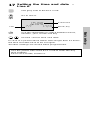
Danfoss ECL Comfort 200 - P30 Operating instructions
- Type
- Operating instructions
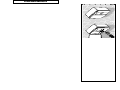
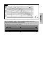
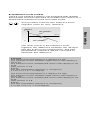
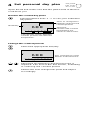
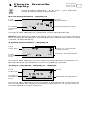
Danfoss ECL Comfort 200 - P30 is a versatile temperature control solution for heating systems. It offers precise room temperature adjustment, energy savings, and pump protection features. With its user-friendly interface, you can easily set up and customize heating schedules, ensuring optimal comfort and efficiency.
Danfoss ECL Comfort 200 - P30 is a versatile temperature control solution for heating systems. It offers precise room temperature adjustment, energy savings, and pump protection features. With its user-friendly interface, you can easily set up and customize heating schedules, ensuring optimal comfort and efficiency.


-
 1
1
-
 2
2
-
 3
3
-
 4
4
-
 5
5
-
 6
6
-
 7
7
-
 8
8
-
 9
9
-
 10
10
-
 11
11
-
 12
12
-
 13
13
-
 14
14
-
 15
15
-
 16
16
-
 17
17
-
 18
18
-
 19
19
-
 20
20
-
 21
21
-
 22
22
-
 23
23
-
 24
24
-
 25
25
-
 26
26
-
 27
27
-
 28
28
-
 29
29
-
 30
30
-
 31
31
-
 32
32
-
 33
33
-
 34
34
-
 35
35
-
 36
36
-
 37
37
-
 38
38
-
 39
39
-
 40
40
-
 41
41
-
 42
42
-
 43
43
-
 44
44
-
 45
45
-
 46
46
-
 47
47
-
 48
48


Danfoss ECL Comfort 200 - P30 Operating instructions
- Type
- Operating instructions
Danfoss ECL Comfort 200 - P30 is a versatile temperature control solution for heating systems. It offers precise room temperature adjustment, energy savings, and pump protection features. With its user-friendly interface, you can easily set up and customize heating schedules, ensuring optimal comfort and efficiency.
Ask a question and I''ll find the answer in the document
Finding information in a document is now easier with AI
Related papers
-
Danfoss ECL Comfort 300, card F11 Operating instructions
-
-
-
-
-
-
-
-
-
Danfoss ECL Comfort 300 - C35 Operating instructions
