BrandMotion SUTV-8849 Installation guide

Category
Car kits
Type
Installation guide

BrandMotion SUTV-8849 is an adjustable rear vision system with a CMOS camera that enhances your vehicle's safety and convenience. Specifically designed for Jeep Wrangler JK models, it seamlessly integrates with your factory display to provide a clear view behind your vehicle. The system features a 5th wheel camera mount for flexible positioning, allowing you to adjust the camera angle for optimal visibility.

BrandMotion SUTV-8849 is an adjustable rear vision system with a CMOS camera that enhances your vehicle's safety and convenience. Specifically designed for Jeep Wrangler JK models, it seamlessly integrates with your factory display to provide a clear view behind your vehicle. The system features a 5th wheel camera mount for flexible positioning, allowing you to adjust the camera angle for optimal visibility.

SummitView™ Jeep Wrangler (JK)
Adjustable Rear Vision System
with CMOS
Camera For Factory Display
SUTV-8849
Product Features
Install Time
Recommended Tools
1hr 30m - 2hr
Wrench
Socket SetScrew Driver Panel Removal Tool Zip Ties
Wire Strippers Wire Cutters Electrical Tape
Questions? Call the Brandmotion technical support line at (734) 619-1250 or CLICK HERE
Installation Instructions - SUTV-8849
Page 1/13AR_03_23_21
Kit A
Components for installing the SUTV-8849
Kit Contents
Vehicle Application:
Jeep Wrangler JK
Part Number: SUTV-8849
Kit Contents:
1x
CMOS Camera
1x Adjustable 5th Wheel Camera Mount
1x Video Chassis Harness
1x RCA to Factory 22 Pin connector
3x
15x Zipties
1x Dual Camera Interface
Push Nuts
Installation Instructions - SUTV-884
9 Page 2/13AR_03_23_21
Access the Radio
Preparing the Radio
Part 1
1. First, you need to gain access to the back of
your aftermarket radio. If you already have
access, skip to part 2.
2. Start by removing the rubber bin insert from
the top of the dash
3. Remove the 7mm bolt under the rubber bin
insert.
4. Using a plastic trim removal tool, remove the
window switch panel.
5. Disconnect harness from window switches.
6. Remove the 7mm bolt behind the window
switch panel.
7. Remove driver knee bolster cover
8. Remove (2) 7mm bolts on both sides of the
steering column.
9. Remove center stack/cluster trim
10. Remove the glove box for access. You will
need access to the area behind the glove box
to make your connection to the radio.
11. Remove (4) 7mm bolts to remove radio from
dash
2 4
7 9
10 11
Installation Instructions - SUTV-884
9 Page 3/13AR_03_23_21
Vehicle Application:
Jeep Wrangler JK
Part Number: SUTV-8849
Installation Instructions - SUTV-884
9 Page 4/13AR_03_23_21
Module Conguration
Part 1
Before Installing:
Install the Video Interface
Vehicle Application:
Jeep Wrangler JK
Part Number: SUTV-8849
Installation Instructions - SUTV-884
9 Page 5/13AR_03_23_21
Power and Signal Connection
Part 2
BACKUP CAMERA ADD-ON
With
IMPORTANT NOTE: SET DIP SWITCHES BEFORE PROCEEDING
DISCONNECT
J1 (6-Pin) Jumper from ARC CHRY52R2 or ARC
CHRY22 T-Harness. Set jumper aside.
CONNECT
257357 Module to 6-Pin Connector
CONNECT
12-PIN ARC-ACC357 Accessory Harness to 257357
M odule
CONNECT
"CAMERA IN " on T-Harness to " VIDEO OUT " on
AR C-ACC357
"OEM CAM OUT " has NO CONNECTION
CONNECT
Camera power to "ACC 12V+ OUTPUT"
Do not use Reverse output to power camera
CONNECT
Camera ground to "GROUND OUTPUT"
CONNECT
(Optional) Switched +12V -or- Ground to " AUX
CAM TRIGGER " for manual 2nd camera activation
CONNECT
Aux Camera Video Output to " AUX CAM INPUT "
(Optional)
CONNECT
T-Harness in vehicle between factory radio and
factory radio connector.
VERIFY
All connections per diagram
SWITCH
IGNITION TO ON/ACC (Do not Start Engine)
For
Push-to-Start, Do not Press Brake
WAIT
For radio to fully power on
SWITCH
IGNITION TO OFF
REMOVE KEYS from ignition
WAIT
3 Minutes for vehicle to fully enter "Sleep" mode
*Close and lock all doors
*Move proximity keys away from vehicle
REPEAT
Programming & Connections
WIRING CONNECTIONS
MADE WITH VEHICLE IGNITION OFF
Programming Instructions
VEHICLE MUST PERFORM TWO FULL POWER CYCLES FOR
SUCCESSFUL PROGRAMMING
Note: If only adding rear camera, output from the camera can be connected directly to
Vehicle Application:
Jeep Wrangler JK
Part Number: SUTV-8849
Installation Instructions - SUTV-884
9 Page 6/13AR_03_23_21
Power and Signal Connection
Part 3
Vehicle Application:
Jeep Wrangler JK
Part Number: SUTV-8849
Installation Instructions - SUTV-884
9 Page 7/13AR_03_23_21
Camera Operation
Part 4
Before Installing:
-
-
-
-
to 7MPH.
IMPORTANT NOTES
The green
-
-
-
newer
DIP Switch #6 = OFF
DIP Switch #6 = ON
-
Vehicle Application:
Jeep Wrangler JK
Part Number: SUTV-8849
a.
b.
Camera functionality test (Highly recommended, not required)
Part 1
1. 8837:
2. 8847:
3. 8857:
a. There will be three wires accompanying the
RCA: Red, Green, and Black
b. Using an wire extension (not supplied)
c. Test Camera
a. There will be two wires at the rear of the
harness near the camera
b. Using an wire extension (not supplied)
c. Test Camera
a. There will be two wires accompanying the RCA:
Red and Black
b. Using an wire extension (not supplied)
c. Test Camera
1. Connect twisted red and green directly to positive terminal
of battery
2. Connect Black to negative terminal of battery
1. Connect RCA to Aftermarket radio and
2. Turn Key to on position
3. Place the vehicle in reverse and verify a good image.
1. Twist red and green together = Power
2. Black = Ground
1. Red= Power
2. Black = Ground
1. Red= Power
2. Black = Ground
1. Connect Red wire directly to positive terminal of battery
2. Connect Black to negative terminal of battery
1. Connect RCA to Aftermarket radio
2. Turn Key to on position
3. Place the vehicle in reverse and verify a good image.
1. Connect red wire directly to positive terminal of battery
2. Connect Black to negative terminal of battery
1. Connect RCA to Aftermarket radio and
2. Turn Key to on position
3. Place the vehicle in reverse and verify a good image.
Ground (Black)
12V Power(Red+Green)
Ground (Black)
12V Power (Red)
Ground (Black)
12V Power (Red)
Installation Instructions - SUTV-884
9 Page 8/13AR_03_23_21
Install Rear Camera
Vehicle Application:
Jeep Wrangler JK
Part Number: SUTV-8849
Installing Rear Camera on Tire Carrier
Part 2
1. Remove your spare tire and place the camera
bracket on the top two studs.
2. Secure bracket to carrier using (2) push nuts to
secure the bracket on two top studs.
3. The nylon washer will go on the bottom stud
and will be secured with the third push nut.
4. Place your tire on the carrier and make any
needed adjustments to the camera placement
to see through the wheel spokes.
5. Once the orientation is satisfactory, tighten two
adjustment screws on bracket.
6. Reinstall the spare tire on the carrier.
1. Using a plastic trim removal tool, remove
interior panels on the inside of the rear gate
2. Insert camera connector through the rear
relief/vent flap behind the spare tire mount.
DO NOT RUN THROUGH CENTER HOLE OF TIRE
CARRIER
3. Gently pull harness through relief door and
connect your camera harness to your chassis
harness.
4. Use supplied wire ties to secure chassis
harness to existing harness in the tailgate.
Install Rear View Camera Chassis Harness
1
5
3
6
2
3
Installation Instructions - SUTV-884
9 Page 9/13AR_03_23_21
Vehicle Application:
Jeep Wrangler JK
Part Number: SUTV-8849
5. Use supplied wire ties to secure chassis
harness to exterior of fabric factory wire cover
connecting tailgate to body. Do not run though
fabric factory wire cover. CAUTION: Leave
enough slack to allow the gate to open fully
6. Using a plastic trim removal tool, remove rear
access (behind seat belt) panel to expose 10mm
bolt, and remove bolt. Failure to remove this bolt
will break the panel.
7. Remove interior rear quarter panel
8. FOR 8848, you will need to ground black wire at
a good chassis ground. Isolate the red wire with
electrical tape. You will connect to power at the
front of the vehicle in later steps.
9. Pull back carpet and continue running chassis
harness forward under sill plates and B-pillar
cover to passenger kick panel
10. Use a plastic trim removal tool to remove the
(2) plastic push pins and remove passenger sill
plate/kick panel.
11. Run the chassis harness behind the glove box
and into the radio cavity.
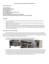
Ground (Black)
12V Power(Red+Green)
Part 1
Connecting to Power
1. 8837:
a. There will be three wires accompanying the RCA
in the passenger kick panel: Red, Green, and Black
b. Identify power output from your aftermarket radio
1. Twist red and green together = Power
2. Black = Ground
Installation Instructions - SUTV-884
9 Page 10/13AR_03_23_21
Vehicle Application:
Jeep Wrangler JK
Part Number: SUTV-8849
a.
Ground (Black)
12V Power (Red)
Ground (Black)
12V Power (Red)
c. Connect twisted red and green wire to power
output from radio
d. Connect black wire to Chassis ground. We
recommend using factory chassis grounding point.
2. 8847:
3. 8857:
a. Identify red power wire exiting the back of the
yellow RCA from your camera chassis harness
b. Identify power output from your aftermarket radio
c. Connect Red wire to power output from your
aftermarket radio
d. Connect black wire to Chassis ground. We
recommend using factory chassis grounding point.
a. Connect jumper power harness to chassis
harness (if not already connected)
b. Separate power and ground wires at jumper
harness
c. Identify power output from your aftermarket
radio
d. Connect red wire to power output from your
aftermarket radio.
e. Connect black wire to Chassis ground. We
recommend using factory chassis grounding point.
1. Red = Power
2. Black = Ground
Installation Instructions - SUTV-884
9 Page 11/13AR_03_23_21
Jeep Wrangler JK 12V Power Location
(White/Grey wire by passenger kick panel)
Vehicle Application:
Jeep Wrangler JK
Part Number: SUTV-8849
Install Forward Facing Camera
Part 1
1. Power the camera harness with 12V, connect
the camera to the harness and plug the Yellow
RCA into the video in port to test the camera
functionality.
2. Route the harness away from any moving
parts so the harness will not get cut. Enter the
underhood area and secure to the harness
running along the driver’s side fender with zip
ties.
3. Route the camera harness into the vehicle’s
interior through the factory grommet in the
firewall on the driver’s side.
4. Route the harness to the back of the radio
where the display interface will be.
5. We recommend to connect to 12V+ from a
vehicle ignition source. The ground should be
located on a chassis ground point.
Installation Instructions - SUTV-8849
Page 12/13AR_03_23_21
Kit Contents
1
2
Vehicle Application:
Jeep Wrangler JK
Part Number: SUTV-8849
FAQ Section
Installation of the Rear Vision Camera
WARNING: Cancer and Reproductive Harm -
www.P65Warnings.ca.gov
Installation Instructions - SUTV-8849
Page 13/13AR_03_23_21
Vehicle Application:
Jeep
Wrangler JK
Part Number: SUTV-8849
  • Page 1 1
  • Page 2 2
  • Page 3 3
  • Page 4 4
  • Page 5 5
  • Page 6 6
  • Page 7 7
  • Page 8 8
  • Page 9 9
  • Page 10 10
  • Page 11 11
  • Page 12 12
  • Page 13 13

BrandMotion SUTV-8849 Installation guide

Category
Car kits
Type
Installation guide

BrandMotion SUTV-8849 is an adjustable rear vision system with a CMOS camera that enhances your vehicle's safety and convenience. Specifically designed for Jeep Wrangler JK models, it seamlessly integrates with your factory display to provide a clear view behind your vehicle. The system features a 5th wheel camera mount for flexible positioning, allowing you to adjust the camera angle for optimal visibility.

Ask a question and I''ll find the answer in the document

Finding information in a document is now easier with AI