5
APPLICATIONS INCLUDE:
• Indoor Pools • Night Clubs
• Spa's • Locker Room
• Health Centers • High humidity Applications
POWER & WEIGHT
• Volts 120V
• Amperage 10.6 Amps Total
• Weight 116 Kg (255 Lbs)
• Shipping Weight 134 Kg (295 Lbs)
• Blowers (x4) 115V, 60 Hz, 2.7 Amps
• Phase Single
SHR 14105R
Light Commercial HRV
The Fantech SHR14105R is
designed to provide an economi-
cal solution for high humidity
applications such as indoor
swimming pools, spas and fit-
ness facilities. The higher humid-
ity generation rate in these appli-
cations leads to annoying window
condensation, mold and struc-
ture deterioration. It’s designed to reduce the occurrence of
condensation in the indoor environment by first operating in
recirculation mode, moving air around the structures, sweeping
windows dry and eliminating troublesome cold spots, then
switching to air exchange mode as needed. Air exchange mode
simply exhausts humid air to the outside and replaces it with
drier air from outside. The airstreams are separated by an
energy efficient heat recovery core which uses the energy in the
exhaust air to lower the load on the HVAC system. Automatic
defrost and provisions for condensation are standard.
SPECIFICATIONS
CASE 20 gauge G90 galvanized steel coated with baked
powder paint, insulated with 25mm (1 inch) and 50mm (2
inch) on outdoor air side foil-faced high density polystyrene
foam for condensation control.
BLOWERS Four (4) maintenance-free Ebm-Papst™ backward
inclined motorized impellers with permanently lubricated sealed
ball bearings and (TOP) thermal overload protected.
HEAT RECOVERY CORE The Heat recovery Cores are fixed plate
cross-flow heat exchanger using 1100 alloy aluminum and
capable of transferring sensible heat between air streams.
The heat recovery cor
es are engineered with a turbulence
inducing geometry in order to maximize heat transfer while
allowing an effective evacuation of condensate. The plates are
hemmed to avoid cross-contamination of airstreams.
FILTERS The exhaust and fresh air streams are protected by
MERV1 washable filters constructed to meet UL Class2.
Optional MERV6 filters are direct replacement to the MERV1.
Use of MERV6 filters will add an additional system pressure
of 90 Pa (0.36in.wg) at 665 l/s (1410cfm).
MOUNTING Unit can be rod mounted or seated on a
platform. Flanged connections are provided for suitable
ductwork connections. Unit shall be adaptable for easy
service of electrical components.
CONTROLS External three (3) position (Low/Standby/Medium)
rocker switch that will offer continuous ventilation. Compatible
with all Fantech HRV/ERV controls.
FROST CONTROL During the defrost sequence, a motorized
damper temporarily blocks the incoming fresh air stream so
that the warm air from the building can circulate thr
ough the
HRV. The exhaust blower shuts down and the supply blower
switches into high speed to maximize the effectiveness of the
defrost strategy.
SERVICEABILITY Unit has hinged or screwed access panels on
front and back. Cores, filters, motors and drain pan are
serviceable from either sides of the unit. Fan assemblies are
mounted on a removable sliding base. Heat recovery cor
es are
mounted in slide-out rails for ease of inspection, removal and
cleaning. Accessibility to the electrical box is maintained for
any unit installation.
0
50
100
150
200
250
275
300
350
400
450
500
550
600
650
700
750
800
850
900
950
1000
1050
1100
1150
1200
1250
1300
1350
1400
1450
1500
1550
2007-10-01
200
1400
0.0
0.4
0.8
1.2
1.6
0 600 1200 1800
0
99
199
298
398
0 283 566 849
0.0
0.5
1.0
1.5
2.0
0 600 1200 1800
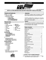
External Static Pressure, (in wg)
External Static Pressure (Pa)
High
Recirculation
Medium
Low
0
50
100
150
200
250
275
300
350
400
450
500
550
600
650
700
750
800
850
900
950
1000
1050
1100
1150
1200
1250
1300
1350
1400
1450
1500
1550
2007-10-01
200
1400
30%
50%
70%
90%
0 600 1200 1800
Airflow Performance
Airflow (l/s)
Airflow (cfm)
External Static Pressure, (in wg)
External Static Pressure (Pa)
Thermal Effectiveness
Airflow (l/s)
Effectiveness
Airflow (cfm)