Page is loading ...

Light commercial models
Commercial Heat Recovery Ventilators
Installation Manual
Item #: 427685
Rev Date: 2018-02-02
SHR6904 • SHR6905R • SHR8004 • SHR11004 • SHR11005R • SHR14104
Your ventilation system should be installed in conformance with the appropriate provincial requirements or, in the absence of
such requirements, with the current edition of the National Building Code, and / or ASHRAE’s “Good Engineering Practices”.
Fantech reserves the right to modify, at any time and without notice, any or all of its products’ features, designs,
components and specifications to maintain their technological leadership position.
Please visit our website www.fantech.net for more detailed technical information.
United States
10048 Industrial Blvd., Lenexa, KS, 66215
Tel.: 800.747.1762 • Fax: 800.487.9915
Canada
50 Kanalflakt Way, Bouctouche, NB, E4S 3M5
Tel.: 800.565.3548 • Fax: 877.747.8116

2
Note Warning/
Important
note
Information Technical
information
Practical tip
PLEASE READ THIS MANUAL BEFORE INSTALLING UNIT
Before installation, careful consideration must be given to how this system will operate if connected to any other
piece of mechanical equipment, i.e. a forced air furnace or air handler, operating at a higher static pressure. After
installation, the compatibility of the two pieces of equipment must be confirmed by measuring the airflows of the
Heat / Energy Recovery Ventilator. It is always important to assess how the operation of any HRV/ERV may inter-
act with vented combustion equipment (i.e. Gas Furnaces, Oil Furnaces, Wood Stoves, etc.).
Never install a ventilator in a situation where its normal operation, lack of operation or partial failure may result
in the backdrafting or improper functioning of vented combustion equipment!!!
Products are designed and manufactured to provide reliable performance, but they are not guaranteed to be 100%
free of defects. Even reliable products will experience occasional failures, and this possibility should be recognized
by the user. If these products are used in a life support ventilation system where failure could result in loss or injury,
the user should provide adequate back-up ventilation, supplementary natural ventilation or failure alarm system, or
acknowledge willingness to accept the risk of such loss or injury.
Your ventilation system should be installed in accordance with the local building code that is in effect. In absence
of such requirements, it is recommenced to check with local authorities having jurisdiction in your area prior to
installing this product.

3
Understanding Fantech Product Numbers
SHR 6904
S = Side Ducting
H = Heat Recovery
R = Remote Control Option
690 = 690cfm @0.4 W.G
4 = Four Ports
5 = Five ports
R = Recirculation
Table of content
INSTALLATION
Location ...........................................................................4
Port Configuration .....................................................................5
Installing Drain Line ....................................................................5
Installing Duct Connections...............................................................6
AIRFLOW BALANCING ........................................................................7
Bypass Module (BPM)
Installing the BPM .....................................................................8
INSTALLATION EXAMPLES
Fully Dedicated Systems.................................................................9
Partially Dedicated Systems (direct connections) ...............................................9
Partially Dedicated Systems (indirect connections) .............................................10
Simplified Installation ..................................................................10
MODES OF OPERATION .......................................................................11
Speed Setting .......................................................................12
LOW VOLTAGE CONTROL SYSTEMS ..............................................................13
MAINTENANCE .............................................................................14
ELECTRICAL CONNECTIONS
SHR 6904 / SHR8004 / SHR11004 / SHR14104 .............................................15
SHR6905R / SHR11005R ..............................................................16
INSTALLATION VERIFICATION TEST
SHR 6904 / SHR8004 / SHR11004 / SHR14104 .............................................18
SHR6905R / SHR11005R ..............................................................19
PARTS LISTS
SHR6904 ..........................................................................41
SHR6905R.........................................................................42
SHR8004 ..........................................................................43
SHR11004 .........................................................................44
SHR11005R........................................................................45
SHR14104R........................................................................46

4
Installation
Location
The HRV must be located in a heated space where it will be possible to conveniently service the unit. Typically the HRV would be located in the
mechanical room, above a drop ceiling or an area close to the outside wall where the weatherhoods will be mounted. Attic installations are not normally
recommended due to extreme temperatures, and difficulty in performing required service & maintenance. If an attic is selected, special care should be
taken in ensuring the unit will perform as intended. Unit may need to be protected with insulated shelter, built on site.
Connecting appliances to the HRV It is not recommended, including:
• clothes dryer
• kitchen exhaust hoods
• combustion venting
• central vacuum system
These appliances may cause lint, dust or grease to collect in the HRV , damaging the unit.
Connecting any of these type of appliances to the HRV will invalidate your warranty
A
B
C
D
E
F
G
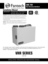
Model A B C D E F G
Kg lbs Kg lbs in. mm. Kg lbs Kg lbs Kg lbs in. mm.
SHR 6904/6905R 23.8 22.5 22.5 49.6 15.4 390 85 187 20 44 18.8 41.3 17.6 448
SHR 8004 20 44 17 37.5 15.9 404 71.5 158 19 41.9 16.5 36.4 11 282
SHR 11004/11005R 30.4 67 27 60 21.4 544 109 241 27.7 61 24.3 53.5 18 455
SHR 14104 29.2 64.4 24.5 54 19 483 116 255 30 66.2 34.7 76.5 10 254

5
Installing Drain Line
Through normal operation and including defrost mode, the HRV may produce some condensation. This water should flow into a nearby drain, or be taken
away by a condensate pump. The HRV and all condensate lines must be installed in a space where the temperature is maintained above the freezing
point. A “P” trap should be made in the drain line. This will prevent odors from being drawn back up into the unit.
Install the drain hose, making a “P” trap
Port configuration
The unit has access doors on the front and back. Also, the main control panel may be moved from front to back allowing for ducting layout.
SHR 6904, SHR 6905R, SHR 11004, SHR 11005R
COLD SIDE
COLD SIDE
WARM SIDE
WARM SIDE
SHR 8004, SHR 14104
WARM SIDE
WARM SIDE COLD SIDE
COLD SIDE
Factory Setting. Unit may be easily reversed
in eld.
Factory Setting. Unit may be easily reversed
in eld.

6
Installing ducts going to / from outside
Installing the ducting to the weatherhoods
Outside weatherhoods
The weatherhoods must have built-in "bird" screens with 1/4 inch (6.35 mm) minimum mesh to prevent birds and rodents from entering into the
ductwork. Do not use smaller mesh as it will be very susceptible to plugging up. The preferred location of the weatherhoods is:
• No less than 10 ft. (3 m) apart from each other.
• At least 18 inches (457.2 mm) above snow line or ground level.
• Supply hood must be kept away from sources of contaminants, such as automobile exhaust fumes, gas meters, garbage cans, containers,
cooling towers, tar roofs, etc.
• Avoid prevailing winds, whenever reasonably possible.
The outside perimeter of the weatherhood must be sealed to prevent leakage into the building.
The design and size of the weatherhoods or louvers chosen by the installer must allow for adequate free area. Water and snow penetration of the system
is minimized when the airflow does not exceed 1000 FPM (5.08 m/s) free area velocity.
Ducting from the weatherhoods –To and From the hrv
Galvanized sheet metal ducting with sufficient cross section with an integral single piece of insulated wrap with vapor barrier should be used to connect
the HRV to the weatherhoods. The R-value of the insulation should be adequate for condensation control. Insulated flex duct may be used in moderation,
if sized and installed properly. (Consult local codes)
All ducts should be sealed using a good bead of high quality caulking (preferably acoustical sealant) and a high quality aluminum foil tape, or other
approved duct sealant.

7
Exhaust air ducting
The stale air exhaust system is used to draw air from the points in the building where the worst air quality problems occur. ( See installation
examples in the manual.)
Installing ducts to / from inside
Direct connection to furnace/ air handler return duct
• Should you wish to hard duct the supply air directly into the cold air return of the HVAC systems, remember to check the airflow balance of the HRV
with the HVAC systems fan both “on”and “off” to determine that it does not imbalance the HRV more than 10%. Make sure you respect the minimum
distance from the supply air in of the HRV and the HVAC systems.
• It may be necessary to install a separate fresh air supply ductwork system if the heating is other than forced air.
When installing an HRV, the designer and installer should be aware of local codes that may require smoke detectors and/or firestats in the HVAC
or HRV ductwork.
Because an HRV is designed to bring fresh air into the building, structures may require supply voltage interrupt when smoke or flame sensors are
triggered, or when a central fire alarm system is activated.
To maximize airflow in the ductwork system, all ducts should be kept short and have as few bends or elbows as possible. Forty-five degree are
preferred to 90 elbows. Use “Y” tees instead of 90 elbows whenever possible.
All duct joints must be fastened with screws or duct sealant and wrapped with a quality duct tape to prevent leakage. Aluminum foil duct tape is
recommended.
Supply air ducting
In buildings without a forced air HVAC systems, fresh air should be supplied to all habitable areas. It should be supplied from high wall or ceiling
locations. Grilles that diffuse the air comfortably such as grille {MGE (metal) or CG (plastic)} grilles with "coanda effect" are recommended.
Optional inline duct heaters may be used to add heat if required.
A The duct’s airflow velocity
is generally measured
with a magnehelic gauge
and a pitot tube.
• To avoid airflow turbulence
and incorrect readings, the
airflow velocity should be
measured on steel ducting
a minimum of 3 duct
cross-sections from the
unit or elbow and before
any transition.
• The balancing procedure consists of measuring the exhaust air leaving the system and the supply air entering the system and ensuring that these
two are equal. A deviation of 10% or less is acceptable.
Airflow balancing
A*
Pitot tube and gauge
A professional air balancer should be contacted to commission the system properly. A skilled HVAC Tech may complete the balance
of air providing they possess the proper equipment. Call Fantech Technical support for assistance.

8
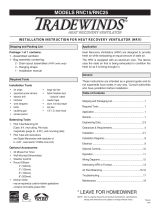
Installing BYPASS Module (BPM) - SHR6905R/SHR11005R
Kit content
• 1x BPM assembly
• 1x bracket "A"
• 2x bracket "B"
• 10x Screws
• 1x black extension wire*
• 1x red extentson wire*
* Only used when electrical box is
reversed
Bracket "A"
Bracket "B"
Figure 1
Bracket "B" Installed
Figure 2
Bracket "A Installed
Figure 3
BPM Tilted
Figure 4
BPM Fastening
Figure 5
Bracket "B" tightened
1. Loosely fasten both
brackets “B” to cabinet
using screws in the pilot
holes (Fig. 1). Don’t drive
the screw all the way;
leave about ¼” of thread
for the step 4.
2. Using the same screw
already on the unit,
assemble bracket “A” on
the cabinet (Fig. 2).
3. Install BPM by tilting it
(Fig. 3) so that the hole
on the mounting bracket
“A” lines up with the
pilot hole on top of the
BPM. Secure it with the
fastener and release
the BPM. The tilting
will enable the hole to
line up properly and will
compress the gasket
once released.
4. Assemble the remaining fasteners to secure the BPM
(Fig. 4). Continue to tighten the fasteners holding the
bracket “B” to cabinet in order to compress the gasket
between the BPM and the cabinet (Fig. 5).
Figure 6
Insert damper motor wires
through bushing
Figure 7
HCE Controller, showing "N.O."
terminal location and "C" terminal
location
5. Next route the damper motor wires through the plastic bushing (Fig.6) of
the electrical box and run the wires to the HCE controller on the terminal
marked “N.O.” in the eld marked “DAMPER” and on the terminal marked “C”
in the eld marked “24VAC”. (Fig. 7)

9
Installation examples
* Drawings are illustrations only and actual port locations and airflow directions may vary, consult unit spec sheets.
It is the responsibility of the installer to ensure all ductwork is sized and installed as designed to ensure the system will perform as intended.
The amount of air (CFM) that an HRV will deliver is directly related to the total external static pressure (E.S.P.) of the system. Static pressure
is a measure of resistance imposed on the blower by length of duct work/number of fittings used in duct work, duct heater etc.
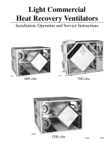
Fully Dedicated System
• Stale air drawn from areas of contamination
• Fresh air supplied to main areas
• HRV airflow should be balanced
• External heating or cooling coil may be needed if air is not able to mix comfortably.
SUPPLY IN
EXHAUST OUT
HRV UNIT
SUPPLY DUCT
RETURN AIR DUCT
EXHAUST AIR TO HRV UNIT
AIR HANDLER UNIT
SUPPLY IN
BALANCING DAMPERS
SUPPLY IN
EXHAUST OUT
HRV UNIT
SUPPLY IN
BALANCING DAMPERS
Partially Dedicated System (Direct Connection)
• Stale air drawn from areas of contamination
• Fresh air supplied to return of air handler
• Air Handler blower may need to operate when call for ventilation
• HRV airflow should be balanced

10
Installation examples (Cont'd)
* Drawings are illustrations only and actual port locations and airflow directions may vary, consult unit spec sheets.
It is the responsibility of the installer to ensure all ductwork is sized and installed as designed to ensure the system will perform as intended.
The amount of air (CFM) that an HRV will deliver is directly related to the total external static pressure (E.S.P.) of the system. Static pressure
is a measure of resistance imposed on the blower by length of duct work/number of fittings used in duct work, duct heater etc.
SUPPLY IN
EXHAUST OUT
HRV UNIT
RETURN AIR DUCT
AIR HANDLER UNIT
SUPPLY IN
BALANCING DAMPERS
SUPPLY IN
EXHAUST OUT
HRV UNIT
SUPPLY DUCT
EXHAUST AIR TO HRV UNIT
12" BREATHER SPACE
CEILING RETURN AIR PLENUM
AIR HANDLER UNIT
SUPPLY IN
BALANCING DAMPERS
Simplified Installation
• Stale air drawn from return of air handler
• Fresh air supplied to return of air handler, further down
stream of HRV exhaust
• Air Handler blower must operate when HRV is providing
ventilation
• HRV airflow should be balanced
Partially Dedicated System (Indirect Connections)
• Stale air drawn from areas of contamination
• Fresh air supplied into ceiling return air plenum or grille
• HRV airflow should be balanced

11
1. Continuous / Ventilation Mode
In this mode of operation both fans are operating and exchanging air with the outside. The
heat recovery ventilator (HRV) constantly exchanges the air at the rate you select, either
at low or medium speed, and switches to high speed when activated by an optional remote
control. The "Low (reduced)" and "High (Normal)" fan speed selection will cause the unit
to operate in continuous exchange mode at a reduced exchange rate. Continuous mode
is recommended, since pollutants are slowly but constantly being generated in a building.
2. Intermittent / Standby Mode
The system is always on standby and operates at high speed when activated by an
optional remote control (required): "Standby" should be selected if the user wishes to
stop the unit from continuous exchange.
3a. Defrost (SHRXX04 Model) by evacuation
A preset defrost sequence is activated at an outdoor air temperature of 23ºF (-5ºC) and
lower.
During the defrost sequence, the supply blower shuts down & the exhaust blower continues
to ventilate for a preset time. The unit then returns to normal operation, and continues the
cycle.
3b. Defrost (SHRXX05R Model)
A preset defrost sequence is activated at an outdoor air temperature of -5ºC (23ºF)
and lower.
During the defrost sequence, the motorized damper in the bypass module (BPM)
temporarily blocks the incoming fresh air stream so that the warm air from the room can
circulate through the HRV. The exhaust blower shuts down and the supply blower
switches into high speed to maximize the effectiveness of the defrost strategy. During
this cycle, the unit will not create a negative pressure. Please note that these systems
are configured to defrost with the BPM devices installed on the fresh air from outside
port. Alternate configuration are available by contacting our technical support department.
Modes of operation
Stale Air
to Outside
Stale Air
from Inside
Recirculate Air from Inside
Supply air
to building

12
The HRV is shipped from the factory on low speed, intermittent operation can be obtained by toggling switch located on outside of cabinet.
The voltage selection for low (reduced) speed of the unit is done via jumpers shown in the illustration below. The default setting 75V.
Setting speed
Low: 75V
(Factory Default)
Low: 90V
Configurable speed control for low (reduced) speed
CAUTION MAKE SURE THE POWER TO THE UNIT IS DISCONNECTED BEFORE MAKING ANY CHANGES

13
AUXILIARY CONTROL – These controls can be paired
RTS2*
• 20- minute timer with LED light
• Boosts system to high speed with the touch of a button
• Up to 5 can be used in one system
• Use in bathroom, kitchen, laundry room
RTS5 • 20/40/60 minute timer with LED light
• Boosts system to high speed with the touch of a button
• Up to 5 can be used in one system
• Use in bathroom, kitchen, laundry room
MDEH1 • Rotary dial Dehumidistat
• Multiple units can be used
• We recommend setting the relative humidity above 80% during the summer
Low Voltage Control Systems
* Please see instruction manuals for individual controls for proper wiring and set up of control systems.
CENTRAL CONTROLS
These control options can only be used individually
CONTROLS FEATURES CONNECT TO
ECO-Touch® • Our most complete, yet easy to use control system
• Sleek design with backlight touchscreen LCD
• ECO mode selects the best operating mode and speed for the season,
minimizing energy use associated with ventilation
• Set preferred indoor relative humidity range and ventilation mode for day
and night conditions
• No battery to replace, all programmed settings are retained during power
outage
• Maintenance reminder indicator
• Error code messages reduce troubleshooting time
EDF7
• MODE button provides 3 modes of operations: Ventilation , Recircula-
tion and Standby
• User selected fan speed: Reduced, Medium, Normal and 20 minutes
per hour
• AUTO setting allows the homeowner to deactivate the dehumidistat
• When the humidity exceeds the desired setpoint, the ventilation sys-
tem operates at Normal speed.
• Once the desired humidity level is achieved, your ventilation system
resumes to its previous mode of operation
EDF1 / EDF1R • Press button once for continuous Reduced speed
• Press button twice and the unit will cycle 20 minutes ON/ 40 minutes
OFF and repeat
• EDF1 – Press button a third time and the system will run continuously
on HIGH speed
• EDF1R –Press button a third time and the system will run recirculation
on HIGH speed
1. Ensure that unit is not
plugged when connecting
the control
2. Recirculation mode is only
available with the “R” sufx
at the end of the model
number.
The wiring connectors
can be removed for
easier connection.
*Maintain polarity
between control
and HRV
(+ → + ; - → -)
W
W
W
W
W
W
+T
-T
D
D
+T
-T

14
Maintenance
The filters need to be checked and cleaned once a month or when they appear dirty.
filters
The motor - The motors are
factory balanced and lubricat-
ed for life. They require no
maintenance.
The unit - The inside of the
unit should be wiped clean
as needed.
Condensation Pan - Units with
drain hoses should have their
line and connection checked
regularly.
Outside hoods - The outside
hoods need to be checked
every season to make sure
there are no leaves or insects
blocking the airflow. Check
regularly that there are no
pollutants near the intake
hood. Make sure they are
clear of any snow accumula-
tion during the winter months.
Clean core on a average every 3-6 months or as needed.
a) Open access door & remove filters.
b) Carefully grip ends of core and pull evenly outward. Core may be snug, but will slide out of the
channel.
c) Wash the core in warm soapy water or light coil solution.
d) Install clean core
e) Install the clean filters
f) Replace access door
Core installation label on the outer end of the core.
To install the clean Core and Filters.
a) First mount the bottom flange of the core guide into the bottom channel approximately 1/4" (6mm)
b) Mount the left or right side flange of the core guide approximately 1/4" (6mm) followed by the other
side
c) Mount the top flange of the core guide into the top channel approximately 1/4" (6mm)
d) With all four corners in place and the core straight and even, push hard in the centre of the core
until the core stops on the back of the cabinet.
CAUTION MAKE SURE UNIT IS UNPLUGGED BEFORE ATTEMPTING ANY MAINTENANCE WORK
The following components should also be inspected regularly and well maintained.
Fixed plate

15
Wiring Diagram SHR6904/SHR8004/SHR11004/SHR14104
Supply
Voltage
ONONON
HIGH
SPEEDS
LOW
5
5
V
JP5 JP3
7
5
V
1
2
0
V
9
0
V
LOW
JP3JP5
HIGH
120V
90V
75V
55V
SPEEDS

16
Wiring Diagram SHR6905R/SHR11005R
Supply
Voltage
ONONON
HIGH
SPEEDS
LOW
5
5
V
JP5 JP3
7
5
V
1
2
0
V
9
0
V
LOW
JP3JP5
HIGH
120V
90V
75V
55V
SPEEDS
ON

17
W
R
G
C
Y
W
R G
Y
Standard Furnace Interlock Wiring
THERMOSTAT
TERMINALS
FURNACE
24-VOLT
TERMINAL BLOCK
FOUR
WIRE
TWO WIRE
heating only
TWO
WIRE
COOLING SYSTEM
W
R
G
C
Y
W
R G
Y
Alternate Furnace Interlock Wiring
THERMOSTAT
TERMINALS
FURNACE
24-VOLT
TERMINAL BLOCK
FOUR
WIRE
TWO WIRE
heating only
TWO
WIRE
COOLING SYSTEM
WIRE JOINT
WIRING DIAGRAM (CONT'D)
WIRING DIAGRAM TO
FURNACE
FOR A FURNACE
CONNECTION TO
A COOLING SYSTEM:
On some newer furnaces and older
thermostats, energizing the R and
G terminal at the furnace has the
effect of energizing the Y at the
thermostat and thereby turning on
the cooling system. If you identify this
type of thermostat, you must use the
“Alternate Furnace Interlock Wiring”
As per building codes and installation requirements for combustion appliances:
Air return ducts, or openings for air return, should not be placed in enclosed spaces containing combustion
appliances that are subject to spillage.

18
Installation Verification Test
SHR 6904, SHR 8004, SHR 11004, SHR 14104 Models
Without external control
1. Fan speed selector switch
• Set fan Speed selector switch to Standby.
2. Start-up
• Apply power to unit
• Unit should enter Exhaust only defrost mode for a 10 second duration and the following should occur:
Exhaust fan runs in HIGH (Normal) speed
Supply fan remains off
3. Standby
• Following the start-up unit should enter Standby mode. The following should occur:
Exhaust fan shuts off
Supply fan remains off
4. LOW (reduced) speed
• Set fans speed selector switch LOW (Reduced) speed. The following should occur.
Exhaust fan runs in LOW (Reduced) speed
Supply fan runs in LOW (Reduced) speed
5. HIGH (normal) speed
• Set fans speed selector switch HIGH (normal) speed. The following should occur.
Exhaust fan ramps up to HIGH (normal) speed
Supply fan ramps up to HIGH (normal) speed
6. Test completion
• Set fan speed selector switch to desired setting
• Installation Verification test is complete
With external control
1. Start-up
• Apply power to unit
• Unit should enter Exhaust only defrost mode for a 10 second duration and the following should occur:
Exhaust fan runs in HIGH (normal) speed
Supply fan remains off
2. External control
• Following start-up unit will respond to external control
• Consult user manual/instruction provided with external controller and ensure unit responds appropriately.
3. Test completion
• Installation Verification test is complete

19
SHR 6905R, SHR 11005R Models
Without External Control
1. Fan speed selector switch
• Set fan Speed selector switch to Standby.
2. Start-up
• Apply power to unit
• Unit should enter Recirculation mode for a 10 second duration and the following should occur:
Supply fan runs in HIGH (Normal) speed
Exhaust fan remains off
3. Standby
• Following the start-up unit should enter Standby mode. The following should occur:
Supply fan shuts off
Exhaust fan remains off
4. LOW (Reduce) speed
• Set fans speed selector switch LOW (Reduce) speed. The following should occur.
Supply fan runs in LOW (Reduce) speed
Exhaust fan runs in LOW (REDUCED) speed
5. HIGH (Normal) speed
• Set fans speed selector switch HIGH (Normal) speed. The following should occur.
Supply fan ramps up to HIGH (Normal)speed
Exhaust fan ramps up to HIGH (Normal) speed
6. Test completion
• Set fan speed selector switch to desired setting
• Installation Verification test is complete
With external control
1. Start-up
• Apply power to unit
• Unit should enter Recirculation mode for a 10 second duration and the following should occur:
Supply fan runs in HIGH (Normal) speed
Exhaust fan remains off
2. External control
• Following start-up unit will respond to external control
• Consult user manual/instruction provided with external controller and ensure unit responds appropriately.
3. Test completion
• Installation Verification test is complete
Installation Verification Test

20
Manuel d'installation
Limited Warranty
• The heat recovery aluminum core has a lifetime warranty.
• Fantech HRV's have a warranty that is limited to 3 years on all parts from the date of purchase, including parts replaced during this time period.
If there is no proof of purchase available, the date associated with the serial number will be used for the beginning of the warranty period.
• The motors found in all Fantech HRVs require no lubrication, and are factory balanced to prevent vibration and promote silent operation.
• The limited warranty covers normal use. It does not apply to any defects, malfunctions or failures as a result of improper installation, abuse,
mishandling, misapplication, fortuitous occurrence or any other circumstances outside Fantech’s control.
• Inappropriate installation or maintenance may result in the cancellation of the warranty.
• Any unauthorized work will result in the cancellation of the warranty.
• Fantech is not responsible for any incidental or consequential damages incurred in the use of the ventilation system.
• Fantech is not responsible for providing an authorized service centre near the purchaser or in the general area.
• Fantech reserves the right to supply refurbished parts as replacements.
• Transportation, removal and installation fees are the responsibility of the purchaser.
• The purchaser is responsible for adhering to all codes in effect in his area.
* This warranty is the exclusive and only warranty in effect relative to the ventilation system and all other warranties either expressed or implied are
invalid.
/