Page is loading ...

SHR 1504 • SHR 1505 R(D) • SHR 2004 • SHR 2005 R(D) • SHR 3005 R • SHR 3205RD
VHR 1404 • VHR 1405 R • VHR 2004 • VHR 2005 R • VHR 704
*Leave with Homeowner
Heat Recovery Ventilator Operation Manual
For use with Models

What Are HRVs ?
To understand these products and
their functions, here are a few things
to remember.
Heat Recovery Ventilators (HRVs)
are recommended for colder areas of the coun-
try that have longer heating seasons as well as
drier desert areas of the South.
Heat Recovery Ventilators are complete whole
house ventilation systems that incorporate a
supply fan and an exhaust fan in one unit. The
supply fan draws fresh air in from the outside
and the exhaust fan pushes stale contaminat-
ed air out. The two air streams are separated
by a heat recovery core which tempers the air, making it the most comfortable solution for a
healthy indoor environment.
For information on how these units can help you save energy and lower heating or cooling costs,
read “How Do They Work?”.
2
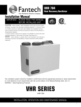
Heat Recovery Ventilators (HRVs)
An HRV is designed to be a cost-effective and reliable
way to bring a continuous supply of fresh air into a
home while exhausting an equal amount of contaminat-
ed air. If it is properly maintained, an HVR can meet a
home's total ventilation requirements by itself. HRVs
use what is called a “sensible” heat recovery core. This
special aluminum core transfers heat from the exhaust
air stream to the incoming air stream. Fresh incoming
air is tempered by the heat that is transferred from the
outgoing air so you save on energy costs. Fantech
HRVs are equipped with automatic defrost mechanisms
so even if you live in the coldest climates, you can use
your HRV all year long.
FRESH AIR
FROM OUTSIDE
EXHAUST AIR
TO OUTSIDE
EXHAUST AIR
FROM INSIDE
FRESH AIR
TO INSIDE
Port Configurations
Five Port Models feature motorized damper for recir-
culation mode and defrost. Positive shut off of supply
port when unit is in standby.
Four Port Models provide constant ventilation even in
defrost mode without the need for additional parts.
An exhaust only (fan shut down) defrost strategy is an
effective method at an affordable price.
Example 1:
VH R14 04 =
Vertical Ports
Heat Recovery Ventilator
Remote Controls
VH R14 04
CFM # PORTS
Example 2:
SH R20 04 =
S ide Ports
Heat Recovery Ventilator
Remote Controls
SH R20 04
CFM # PORTS
Understanding Fantech Model
Numbers
How Do They Work?

3
OPERATION
Winter:
Humidity control is very important during the winter months. This is when problems will
be most apparent since condensation on the windows will often occur. The colder the
outside temperature, the greater the risk of condensation in the home. The average relative
humidity should be maintained between 30-60% to avoid condensation. Low speed con-
tinuous ventilation with high speed override is recommended.
A Heat Recovery Ventilator (HRV) is designed to bring fresh air into a building while exhausting an equal amount of stale air. During
the winter months, the incoming cold fresh air is warmed by utilizing the heat recovered from the stale air before it is exhausted to
the outdoors. During summer months when the indoor space is air conditioned, the HRV will help in cooling the incoming fresh air
using the stale air that is being exhausted.
Fantech HRVs are designed to run continously or intermittently, giving the homeowner complete control over their air quality.
Continuous low speed ventilation is recommended, which will help eliminate carbon dioxide, VOCs and other gases as well as freshen
up the home. Intermittent high speed ventilation can be obtained through a variety of optional remote controls found in this manual.
Below are some examples of seasonal operation of an HRV.
NOTE: Some products may not be exactly as illustrated in the Operation Manual.
Fantech Inc. reserves the right to modify, at any time and without notice, any or all of its products' features, designs, components and
specifications, to maintain their technological leadership position.
Fall:
Rain and rapid temperature changes make it difficult to control the internal humidity level
and may result in condensation on the windows. A remote dehumidistat may help give
greater control over the inside environment.
Summer:
The air is sometimes hot and humid. To stop the warm humid air from entering, set the
dehumidistat at its highest level. If the EDF5 controller is installed, the air exchanger can
be set to cycle the unit on and off as desired from that wall control. However, continuous
ventilation is recommended.
Spring:
Temperatures are more moderate and become warmer each day. To keep the humidity and
temperature uniform, set the dehumidistat higher (if installed). You may also switch the
HRV to standby mode if desired.

MODES OF OPERATION
4
1. Continuous Ventilation Mode
In this mode of operation, both fans are operating and exchang-
ing air with the outside. The heat recovery ventilator (HRV)
constantly exchanges the air at the rate you select, either at
low or medium speed, and switches to high speed when acti-
vated by an optional remote control. The "Low" and "Med" fan
speed selection will cause the unit to operate in continuous
exchange mode at an exchange rate of 35% and 50% maximum
airflow rating respectively. Continuous mode is recommended,
since pollutants are slowly but constantly being generated in
your house.
The switch on the side of the unit is used to toggle between STANDBY, LOW speed and MEDIUM speed modes.
In order to activate HIGH speed, a jumper must be placed between the DEHUM + and DEHUM - contacts.
* no exchange of air
Air from
Outside
Air to
House
Air from
House
Air to
Outside
4. Defrost/Fan shutdown (4 port models)
The automatic defrost cycle for SHR/VHR models of HRVs con-
sists of a fan shutdown. When the supply air stream tempera-
ture goes below -5°C (23°F), the supply fan shuts down and the
exhaust fan goes into "High" speed. Ambient air is passed
through the unit for a period of 5 minutes. The supply fan will
then re-start and run at the presetspeed. The exhaust fan will
also slow down to the preset speed, and the unit will operate in
the run cycle for 25 minutes. This fan shutdown defrost cycle
continues until the supply air
stream rises above 0°C (32°F).
3.Defrost/Recirculation Mode (5 port “R” models)
The automatic defrost cycle for SHR R(D) / VHR R models of
HRVs consists of a damper defrost which allows air to recircu-
late throughout the unit & home. When the supply air stream
temperature goes below -5°C (23°F), the exhaust fan shuts
down, the supply fan goes to "High" speed, and a damper
closes the supply, opening a 5th collar. The ambient air is then
recirculated through the unit & home for a period of 5 minutes.
The unit will then resume normal operation for a time period of
25 minutes. This damper defrost cycle continues until the sup-
ply air stream rises above 0°C (32°F). The recirculation feature
can be obtained with the use of an optional EDF5 control.
2. Intermittent / Standby Mode (SHR(D) / VHR Series of HRVs)
The system is always on standby and operates at high speed
when activated by an optional remote control. "Standby" should
be selected if the user wishes to stop the unit from continuous
exchange. We recommend that the "Standby" mode only be used
if your system is equipped with an optional external control, in
which case, the unit would activate to "High" fan speed, until the
control is satisfied and then return to "Standby" (off).
Air from
House
Air to
House
Air to
Outside
Air from
House

OPTIONAL REMOTE CONTROLS
5
RTS2 - The 20-minute remote timer is typically installed in areas where
contaminated such as moisture and odors, are produced. Simply push the
button and the HRV will activate to high speed for 20 minutes. Up to 5
electronic timers can be installed throughout the building at a distance of up to
500 feet (152 meters) from the HRV.
MDEH2 - The wall-mounted MDEH2 offers the same features of the MDEH1 plus
additional off/on control for the HRV. Dial illuminates when in override mode.
RTS3 - The RTS3 is designed to provide an intermittent boost to the Heat recovery
ventilator. Pressing the fan control button will energize the HRV system into high
speed from a low or standby mode. The ventilator can be set to continue on high for
20, 40, or 60 minutes by pressing the control button one, two or three times,
respectively. Pressing the button a fourth time will cancel the timing function.
EDF1 - The EDF1 is designed to provide 3 modes of operation to the Heat recovery
ventilator. Pressing the “Push” button once initiates the unit to run at a continuous
low speed of operation (green). Pressing the button twice allows the ventilator to
run for 20 minutes and then turns off for 40 minutes (yellow). Touch the button a
third time and the system will run continuously on high (red). The ventilation system
will stay on the last function selected until it is changed.
MDEH1 - The wall mount dehumidistat monitors the humidity level in the area
it is installed. When the humidity level rises above the desired set-point, the
HRV will activate to high speed/override mode. Once the humidity level returns
to desired condition, the unit will return to the normal mode.
To avoid window condensation:
• It is not necessary to
change the humidity control
every day. Monitor the
average weekly
temperature or experiment
with various settings until
you find a level that is
comfortable for you. Adjust
the control when needed.
PRACTICAL
TIPS
* All controls are low voltage. 18 to 24
gauge wire is recommended.
NOTE:
A dehumidistat is ideal for
use in energy efficient
houses where indoor
humidity (during the
heating season) is higher
than outdoor levels. High
humidity is a major cause
of structure damage and
IAQ problems such as mold
and mildew.
2 wire
installation
4 wire
installation
3 wire
installation
2 wire
installation
2 wire
installation
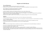
EDF5
MULTI-FUNCTION
WALL CONTROL
Control multiple func-
tions of your HRV with
one slimline wall con-
trol. Two wire connec-
tion simplifies installa-
tion. Use one EDF5 per
HRV installed.
OVERRIDE SPEED
CONTROL
Push to select
override speed of
unit.
CYCLE CONTROL
Set unit to cycle on
15, 20, or 30 min-
utes every hour
MODE SPEED
Set Unit to Low,
Medium or High
Speed
OVERRIDE TIMER
When pressed, unit
will provide high
speed ventilation
for one 15,
30 or 60 minute
period.
DIGITAL DISPLAY
Shows Indoor Humidity Level
This control will not read
below 29% RH
DEHUMIDISTAT CONTROL
(see description on top of this page)
MAINTENANCE LIGHT
Light comes on when
it’s time to clean
unit.
POWER
On/Off and Reset
MODES
Select Intermittent,
Recirculation or
Continuous
Ventilation Modes
NOTE:
When an Intellitek control
is installed, the rocker
switch located on the right
hand side of the HRV will
be automatically
deactivated giving the user
complete control from
wherever he/she wishes to
mount the control pad.
NOTE:
The override speed cannot
be set at a fan speed lower
or equal to the normal
operating fan speed. For
example, if the unit is
normally operating at a
medium fan speed, the
override fan speed will be
automatically set to high.
NOTE:
EDF5 model, changing the
override speed will change
default override speed for
other external controls.
EXAMPLES:
If, on the EDF5 control, you
have set the override
control at medium, and
you start an external
remote control (i.e. RTS2),
the unit will run at medium
speed for 20 min.
PRACTICAL
TIPS
4 1/2"
(114 mm)
Width = 4 1/2" (110mm)
Height = 5 1/8" (130mm)
Thickness = 5/8" (15mm)
5 1/8"
(130 mm)

6
MAINTENANCE
The filters (2) need to be checked and cleaned every
three months or when they appear dirty. Wash in warm
sudsy water (mild detergent). The filters should be
replaced when they can no longer be cleaned properly.
NOTE:
• To prevent electrical shock, check that the
unit is unplugged before performing any
repairs or maintenance.
• A yearly inspection is recommended to
ensure the efficiency and trouble-free use
of your system. Run through the system
and verify the different operating modes.
Heat Recovery Core
Filters
The fan - The fan are factory balanced and lubricated for life. They
require no maintenance.
The unit - The inside of the unit should be vacuumed yearly. Be careful not
to damage any of the mechanical components and electrical connections.
The drain pan and drain line - Units with drain lines should have their
line and connection checked regularly.
Outside hoods - The outside hoods need to be checked every season to
make sure there are no leaves or insects blocking the airflow. Check
regularly that there are no pollutants near the intake hood. Make sure
they are clear of any snow accumulation during the winter months.
Clean Core and Filters Every 3-6 Months. Unplug unit before performing any
repairs or maintenance
a) Open access door.
b) Carefully grip ends of core and pull evenly outward. Core may be snug,
but will slide out of the channel.
c) Once removed from the cabinet, remove filters.
d) Wash core in warm soapy water (do not use dishwasher).
To Install Clean Core and Filters.
a) First, insert the bottom flange of the core guide into the bot-
tom channel approximately 6mm (1/4").
b) Insert the left or right side flange of the core guide approxi-
mately 6mm (1/4"), followed by the other side.
c) Insert the top flange of the core guide into the top channel
approximately 6mm (1/4").
d) With all four corners in place and the core straight and even,
push hard in the center of the core until the core stops at
the back of the cabinet.
CAUTION MAKE SURE UNIT IS UNPLUGGED BEFORE ATTEMPTING ANY MAINTENANCE WORK
The following components should be inspected regularly and well maintained.
The heat recovery core needs to be checked and cleaned every six months. The core can be cleaned using a mild soap and water. Rinse thoroughly.
Handle with care. Hot water and a strong detergent will damage the heat recovery core. It is recommended to clean the core in the summer or when
the temperature is mild. Never clean the heat recovery core during winter.
Filters need to be checked regularly

7
TROUBLESHOOTING
Problem Causes Solutions
Air is too dry – Dehumidistat control is set too low – Increase the desired level of humidity. Change ventilation mode from
continuous mode to standby.
– HRV out of balance – Have contractor balance HRV airflows
Air is too humid – Dehumidistat control is set too high – Reduce the desired level of humidity. Combine this with the use of continu-
ous exchange mode.
– Sudden change in temperature – Wait until outside temperature stabilizes (winter). Heating will also
improve situation.
– Storing too much wood for heating – Store a majority of your wood outside. Even dried, a cord of wood contains
more than 20 gallons of water.
– Dryer vent exhaust is inside home – Make sure the dryer vent is exhausting outside.
– Poor air circulation near windows – Open curtains or blinds.
– HRV out of balance – Have contractor balance HRV airflows
– Well sealed basement door is closed – Open the door or install a grill on the door.
– Failed damper system may be stuck in recirculation
mode
– Check defrost damper. If damper is always blocking incoming fresh air,
have contractor verify damper system.
Persistent condensation
on window
– Improper adjustment of dehumidistat control – Reduce the desired level of humidity. Combine this step with use of
continuous exchange mode.
– HRV out of balance – Have contractor balance HRV
– Poor air circulation near windows – Open curtains or blinds.
Poor Air Flows – 1/4" (6mm) mesh on the outside hoods is plugged – Clean exterior hoods or vents
– Filters plugged – Remove and clean filter
– Core obstructed – Remove and clean core
– Indoor grilles closed or blocked – Check and open grilles
– Inadequate power supply at site – Have electrician check supply voltage
– Ductwork is restricting airflow – Check duct installation
– Improper speed control setting – Increase the speed of the HRV (i.e. change unit control from LOW to MED speed)
– HRV airflow improperly balanced – Have contractor balance HRV airflows
– Ducting has fallen down or been disconnected from HRV – Have contractor reconnect ducting
Supply air feels cold – Poor location of supply grilles, the airflow may irritate
the occupant
– Locate the grilles high on the walls or under the baseboards, install ceiling
mounted diffuser or grilles so as not to directly spill the supply air on the
occupant (eg. Over a sofa)
– Turn down the HRV supply speed. A small duct heater (1kw) could be used
to temper the supply air
– Placement of furniture or closed doors is restricting the movement of air
in the home
– Outdoor temperature extremely cold – If supply air is ducted into furnace return, the furnace fan may need to run
continuously to distribute ventilation air comfortably
HRV and/or Ducts frosting up – HRV air flows are improperly balanced – Have HVAC contractor balance the HRV airflows
– Malfunction of the HRV defrost system – Note: minimal frost build-up is expected on cores before unit initiates
defrost cycle functions
Condensation or Ice Build Up in
Insulated Duct to the Outside
– Incomplete vapor barrier around insulated duct – Tape and seal all joints
– A hole or tear in outer duct covering – Tape any holes or tears made in the outer duct covering
– Ensure that the vapor barrier is completely sealed.
Green LED Light Codes on
Control Board
Constant Flash – Everything is in good operations
Light is ON, and not Flashing – Control Board is defective – Replace Control Board
Light is OFF, and not Flashing – No Power is being transmitted to the Control Board – Make sure unit is plugged.
– Transformer may need replacing.
Note: It is best to get the unit checked by a certified HVAC Contractor/Technician.

Date Maintenance PerformedMaintenance Required Recommended Frequency
8
Fantech, reserves the right to modify, at any time and without notice,
any or all of its products’ features, designs, components and specifi-
cations to maintain their technological leadership position.
Item #:403704
Rev Date: 042710
United States
10048 Industrial Blvd.
Lenexa, KS 66215
Phone: 800-747-1762; 913-752-6000
Fax: 800-487-9915; 913-752-6466
www.fantech.net; [email protected]
Canada
50 Kanalflakt Way,
Bouctouche, NB E4S 3M5
Phone: 800.565.3548; 506.743.9500
Fax: 877.747.8116; 506.743.9600
www.fantech.net; [email protected]
The Best
Limited Warranty
in the Business
• The heat recovery aluminum core has a
limited lifetime warranty.
• The fans found in all Fantech HRVs require
no lubrication, and are factory balanced to
prevent vibration and promote silent
operation.
• The limited warranty covers normal use.
It does not apply to any defects,
malfunctions or failures as a result of
improper installation, abuse, mishandling,
misapplication, fortuitous occurrence or
any other circumstances outside
Fantech’s control.
• Inappropriate installation or
maintenance may result in the
cancellation of the warranty.
• Any unauthorized work will result in
the cancellation of the warranty.
• Fantech is not responsible for any
incidental or consequential damages
incurred in the use of the ventilation
system.
• Fantech is not responsible for providing
an authorized service centre near the
purchaser or in the general area.
• Fantech reserves the right to supply
refurbished parts as replacements.
• Transportation, removal and installation
fees are the responsibility of the purchaser.
• The purchaser is responsible to adhering
to all codes in effect in his area.
• The warranty is limited to 5 years on
parts and 7 years on fans from the date
of purchase, including parts replaced
during this time period. If there is no
proof of purchase available, the date
associated with the serial number will be
used for the beginning of the warranty
period.
* This warranty is the exclusive and only
warranty in effect relative to the ventilation
system and all other warranties either
expressed or implied are invalid.
Check and Clean Filters Every 3 months or if dirty
Check Heat Recovery Core Every 6 months
Check Drain Pan and Lines Every 3 months
Vacuum the Inside of the
Unit
Annually
Clean and Un-block Outside
Hoods
Annually
Clean and Inspect Duct
Work
Annually
General Servicing by a
Qualified Contractor
Annually
HRV MAINTENANCE CHART
* Schedule may be altered to meet your own needs. More frequent servicing may be required depending on
the severity of your home's indoor and outdoor environments.
Contractor Telephone Number Date Serviced

SHR & VHR Models
SHR 1504 • SHR 1505 R • SHR 2004 • SHR 2005 R • SHR 3005 R • SHR 3205RD
VHR 1404 • VHR 1405 R • VHR 2004 • VHR 2005 R
Your ventilation system should be installed in conformance with the appropriate provincial or state requirements
or, in the absence of such requirements, with the current edition of the National Building Code, and / or
ASHRAE’s “Good Engineering Practices”.
IMPORTANT - PLEASE READ THIS MANUAL
BEFORE INSTALLING UNIT
CAUTION - Before installation, careful consideration must be given to how this system
will operate if connected to any other piece of mechanical equipment, i.e. a forced air furnace
or air handler, operating at a higher static pressure. After installation, the compatibility of the
two pieces of equipment must be confirmed by measuring the airflow of the Heat Recovery
Ventilator using the balancing procedure found in this manual.
It is always important to assess how the operation of any HRV may interact with vented com-
bustion equipment (i.e. Gas Furnaces, Oil Furnaces, Wood Stoves, etc.).
NEVER - install a ventilator in a situation where its normal operation, lack of operation or par-
tial failure may result in the backdrafting or improper functioning of vented combustion equipment!!!
SHR & VHR Series
Heat Recovery Ventilator
Installation Manual

2
TABLE OF CONTENTS
DETERMINING YOUR AIRFLOW REQUIREMENT . . . . . . . . . . . . . . . . . . . . . . . . . . . . . . . . . . . . . . . . . . . . . . . . . . . . . 3
TECHNICAL DATA
SHR . . . . . . . . . . . . . . . . . . . . . . . . . . . . . . . . . . . . . . . . . . . . . . . . . . . . . . . . . . . . . . . . . . . . . . . . . . . . . . . 4
VHR . . . . . . . . . . . . . . . . . . . . . . . . . . . . . . . . . . . . . . . . . . . . . . . . . . . . . . . . . . . . . . . . . . . . . . . . . . . . . . 5
HRV INSTALLATION . . . . . . . . . . . . . . . . . . . . . . . . . . . . . . . . . . . . . . . . . . . . . . . . . . . . . . . . . . . . . . . . . . . . . . . . . . 6
EXTERIOR DUCTING INSTALLATION
Weatherhood Location . . . . . . . . . . . . . . . . . . . . . . . . . . . . . . . . . . . . . . . . . . . . . . . . . . . . . . . . . . . . . . . . . . . . . 7
Installing the ducting to the weatherhoods . . . . . . . . . . . . . . . . . . . . . . . . . . . . . . . . . . . . . . . . . . . . . . . . . . . . . . . 7
INTERIOR DUCTING INSTALLATION
General Tips . . . . . . . . . . . . . . . . . . . . . . . . . . . . . . . . . . . . . . . . . . . . . . . . . . . . . . . . . . . . . . . . . . . . . . . . . . . . 8
Installing duct to HRV . . . . . . . . . . . . . . . . . . . . . . . . . . . . . . . . . . . . . . . . . . . . . . . . . . . . . . . . . . . . . . . . . . . . . 8
Supply & Exhaust Air Grilles Location. . . . . . . . . . . . . . . . . . . . . . . . . . . . . . . . . . . . . . . . . . . . . . . . . . . . . . . . . . . 8
Ducting 5th port units . . . . . . . . . . . . . . . . . . . . . . . . . . . . . . . . . . . . . . . . . . . . . . . . . . . . . . . . . . . . . . . . . . . . . 8
INSTALLATION EXAMPLES
Fully dedicated system . . . . . . . . . . . . . . . . . . . . . . . . . . . . . . . . . . . . . . . . . . . . . . . . . . . . . . . . . . . . . . . . . . . . . 9
Partially dedicated system . . . . . . . . . . . . . . . . . . . . . . . . . . . . . . . . . . . . . . . . . . . . . . . . . . . . . . . . . . . . . . . . . 10
Simplified Installation - Option 1 . . . . . . . . . . . . . . . . . . . . . . . . . . . . . . . . . . . . . . . . . . . . . . . . . . . . . . . . . . . . . 11
Simplified Installation - Option 2 . . . . . . . . . . . . . . . . . . . . . . . . . . . . . . . . . . . . . . . . . . . . . . . . . . . . . . . . . . . . . 12
START UP PROCEDURE . . . . . . . . . . . . . . . . . . . . . . . . . . . . . . . . . . . . . . . . . . . . . . . . . . . . . . . . . . . . . . . . . . . . . . 13
AIRFLOW BALANCING. . . . . . . . . . . . . . . . . . . . . . . . . . . . . . . . . . . . . . . . . . . . . . . . . . . . . . . . . . . . . . . . . . . . . . . 13
Adjusting Airflows . . . . . . . . . . . . . . . . . . . . . . . . . . . . . . . . . . . . . . . . . . . . . . . . . . . . . . . . . . . . . . . . . . . . . . . 14
Measuring the airflow using station (grid) method. . . . . . . . . . . . . . . . . . . . . . . . . . . . . . . . . . . . . . . . . . . . . . . . . 14
LOW VOLTAGE CONTROL SYSTEMS . . . . . . . . . . . . . . . . . . . . . . . . . . . . . . . . . . . . . . . . . . . . . . . . . . . . . . . . . . . . . 15
ELECTRICAL CONNECTIONS . . . . . . . . . . . . . . . . . . . . . . . . . . . . . . . . . . . . . . . . . . . . . . . . . . . . . . . . . . . . . . . . . . 16
TROUBLESHOOTING . . . . . . . . . . . . . . . . . . . . . . . . . . . . . . . . . . . . . . . . . . . . . . . . . . . . . . . . . . . . . . . . . . . . . . . . 19
HRV MAINTENANCE CHART . . . . . . . . . . . . . . . . . . . . . . . . . . . . . . . . . . . . . . . . . . . . . . . . . . . . . . . . . . . . . . . . . . 20

3
Example for maximum airflow normally required.
HRVs are typically sized to ventilate the whole house at a minimum of 0.35 air changes per hour.
To calculate, simply take the square footage of the house (including basement) and multiply by the
height of the ceiling to get the cubic volume. Then, divide by 60 and multiply by 0.35.
Example: SQFT of House 1100
Basement 1100
Total SQFT 2200
Height of ceiling x 8
Cubic volume 17600
Minutes per hour / 60
Maximum airflow required (CFM) 293
Minimum air changes per hour x 0.35
Minimum airflow required (CFM) 103
* Always consult your local building codes for sizing requirements in your area.
i.e. Local building codes may require more or less air change per hour.
Room classification Number of rooms CFM (L/s)
CFM Required
Master bedroom x 10 L/s (20 CFM) =
Basement yes or no =
Bedrooms x 5 L/s (10 CFM) =
Living room x 5 L/s (10 CFM) =
Others x 5 L/s (10 CFM) =
Kitchen x 5 L/s (10 CFM) =
Bathroom x 5 L/s (10 CFM) =
Laundry room x 5 L/s (10 CFM) =
Utility room x 5 L/s (10 CFM) =
Total Ventilation Requirements (add last column ) =
if yes add 10 L/s (20 CFM)
if no = 0
1 cfm = 0.47189 L/s
1 L/s = 3.6 m
3
/hr
Alternate Method
DETERMINING YOUR AIRFLOW REQUIREMENT

4
Power
• Volts 120 VAC
• Amperage
SHR 1504/1505R 1.3 Amps
SHR 2004/2005R 2.1 Amps
SHR 3005R 2.8 Amps
SHR 3205RD 2.5 Amps
• Single Phase
A
B C D
F
E
Dimensions Airflow Path
SHR1504
SHR1505R
280
133
154
320
SHR 3205RD
Fresh Air
From Outside
Stale Air
To Outside
Fresh Air
To Inside
Stale Air
From Inside
3 ft, 3 prong
Power Cord
1/2
II
Drain
SHR 1504, SHR 1505R, SHR 2004, SHR 2005R, SHR 3005R & SHR 3205RD
Heat Recovery Ventilators
Fan Performance Performance Data
SHR 3005R Unit is larger to accommodate 2 heat recovery cores. Electrical box is inside cabinet.
Measurements
SHR 1504 SHR 1505 SHR 2004 SHR 2005R SHR 3005R SHR 3205RD
A 56mm (2
1
/
4
") 56mm (2
1
/
4
") 56mm (2
1
/
4
") 56mm (2
1
/
4
") 56mm (2
1
/
4
") 56mm (2
1
/
4
")
B 596mm (23
1
/
2
") 596mm (23
1
/
2
") 707mm (27
7
/
8
") 707mm (27
7
/
8
") 1292mm (50
7
/
8
") 707mm (27
7
/
8
")
C 67mm (2
5
/
8
") 67mm (2
5
/
8
") 67mm (2
5
/
8
") 67mm (2
5
/
8
") 56mm (2
1
/
4
") 71mm (2
3
/
4
")
D 441mm (17
3
/
8
") 441mm (17
3
/
8
") 441mm (17
3
/
8
") 441mm (17
3
/
8
") 441mm (17
3
/
8
") 638mm (25
1
/
8
")
E 413mm (16
1
/
8
") 441mm (17
3
/
8
") 520mm (20
1
/
2
") 520mm (20
1
/
2
") 562mm (22
1
/
8
") 520mm (20
1
/
2
")
F 152mm (6") 152mm (6") 152mm (6") 152mm (6") 152mm (6") 203mm (8")
Apparent
Sensible
Effectiveness at
-25°C (-13°F)
Apparent
Sensible
Effectiveness at
0°C (32°F)
Power
Consumed
Watts
at 0°C (32°F)
Model
SHR 1504 73% @31 L/s (65 CFM) 77% @32 L/s (68 CFM) 72 @31 L/s (65 CFM)
SHR 1505R 73% @31 L/s (65 CFM) 77% @32 L/s (68 CFM) 72 @31 L/s (65 CFM)
SHR 2004 77% @31 L/s (65 CFM) 79% @61 L/s (129 CFM)
108 @31 L/s (65 CFM)
SHR 2005R 77% @31 L/s (65 CFM) 81% @59 L/s (126 CFM)
108 @31 L/s (65 CFM)
SHR 3005R 92% @55 L/s (117 CFM) 91% @57 L/s (121 CFM)
212 @55 L/s (117 CFM)
SHR 3205RD 77% @56 L/s (118 CFM) 79% @58 L/s (123 CFM)
136 @56 L/s (118 CFM)
TECHNICAL DATA

5
NOTE: Some products may not be exactly as illustrated in the Installation Manual.
Fantech Inc. reserves the right to modify, at any time and without notice, any or all of its products’ features, designs, components
and specifications, to maintain their technological leadership position.
wolfriAsnoisnemiD
BA
C
D
E
VHR1405R
0
0.2
0.4
0.6
0.8
1
1.2
0
50
100
150
200
250
300
400 80 120 160
Airflow (cfm)
AirFlow (L/s)
Static Pressure (in WC)
200 240
190 38 57 76 94 114
VHR2004
VHR2005R
VHR 1404
Optional recirculation
duct collar (provided)
with VHR 1405R
& VHR 2005R only
3 ft, 3 prong
Power Cord
1/2
II
Drain
ecnamrofreP naF
VHR1405R
0
0.2
0.4
0.6
0.8
1
1.2
0
50
100
150
200
250
300
400 80 120 160
Airflow (cfm)
AirFlow (L/s)
Static Pressure (in WC)
200 240
190 38 57 76 94 114
VHR2004
VHR2005R
VHR 1404
VHR704
ecnamrofreP naF
Power
• Volts 120 VAC
• Amperage
VHR 1404/1405R 1.3 Amps
VHR 2004/2005R 2.1 Amps
• Single Phase
VHR 1404, VHR 1405R, VHR 2004 & VHR 2005R
Heat Recovery Ventilators
Apparent
Sensible
Effectiveness at
-25°C (-13°F)
Apparent
Sensible
Effectiveness at
0°C (32°F)
Power
Consumed
Watts
at 32°F (0°C)
Model
VHR 1404
73% @31 L/s (65 CFM)
77% @32 L/s (68 CFM)
72 @31 L/s (65 CFM)
VHR 1405R
73% @31 L/s (65 CFM)
77% @32 L/s (68 CFM)
72 @31 L/s (65 CFM)
VHR 2004
77% @31 L/s (65 CFM)
79% @61 L/s (129 CFM)
108 @31 L/s (65 CFM)
VHR 2005R
77% @31 L/s (65 CFM)
81% @59 L/s (126 CFM)
108 @31 L/s (65 CFM)
VHR 1404 VHR 1405R VHR 2004 VHR 2005R
A 604mm (22
3
/
4
") 604mm (22
3
/
4
") 711mm (28") 711mm (28")
B 438mm (17
1
/
4
") 438mm (17
1
/
4
") 438mm (17
1
/
4
") 438mm (17
1
/
4
")
C 413mm (16
1
/
4
") 413mm (16
1
/
4
") 521mm (20
1
/
2
") 521mm (20
1
/
2
")
D 56mm (2
1
/
4
") 56mm (2
1
/
4
") 56mm (2
1
/
4
") 56mm (2
1
/
4
")
E 152mm (6") 152mm (6") 152mm (6") 152mm (6")
Measurements
Fan Performance
Performance Data
Dimensions Airflow Path
TECHNICAL DATA (CONT'D)

6
• Have a nearby power
supply (120 Volts,
60Hz).
• Choose a location which
allows the possibility of
mounting the unit to
supporting beams.
• The unit should be level
in order to allow proper
condensate drainage.
• To minimize noise, do not
install unit in living area.
2 Install the drain hose,
making a “P” trap
HRV INSTALLATION
PRACTICAL TIPS
3 Hang the unit by
slipping a link onto the
hanging hooks, making
sure the unit is level.
2 Attach a hanging chain
(provided) to each 19mm
(3/4") bolt (provided) in the
top 4 corners of the unit
and tighten.
1 Place fastening hooks
on the strapping board
or the floor joists.
1 Install the drain nipple.
Installing Drain Line
Through normal operation and during its defrost mode, the HRV may produce some condensation.
This water should flow into a nearby drain, or be taken away by a condensate pump. The HRV and
all condensate lines must be installed in a space where the temperature is maintained above the
freezing point. A “P” trap should be made in the drain line. This will prevent odors from being
drawn back up into the unit.
MOUNTING
LOCATION
The HRV must be located in a heated space where it will be possible to conveniently service the
unit. Typically the HRV would be located in the mechanical room or an area close to the outside
wall where the weatherhoods will be mounted. If a basement area is not convenient or does not
exist, a utility or laundry room may be used.
Attic installations are not normally recommended due to:
– the complexity of the installation
– freezing conditions in the attic
– difficulty of access for service and cleaning
– no drain access
Connecting appliances to the HRV is not recommended. These include:
– clothes dryer
– range top
– stovetop fan
– central vacuum system
These appliances may cause lint, dust or grease to collect in the HRV, damaging the unit.
NOTE: Connecting any of these type of appliances to the HRV will void your warranty.

7
EXTERIOR DUCTING INSTALLATION
WEATHERHOOD LOCATION
• Decide where your intake and exhaust hoods will be located.
Locating the Intake Weatherhood
• Should be located upstream (if there are prevailing winds) from the exhaust outlet
• At a minimum distance of 3m (10') away from dryer vents and furnace exhaust (medium or high efficiency furnaces), driveways, oil
fill pipes, gas meters, or garbage containers
• At a minimum height of 457mm (18") above the ground, or above the level of expected snow accumulation
• At a minimum distance of 1m (3') from the corner of the building
• Do not locate in a garage, attic or crawl space
Locating the Exhaust Weatherhood
• At least 457mm (18") above ground or above the depth of expected snow accumulation
• At least 1m (3') away from the corner of the building
• Not near a gas meter, electric meter or a walkway where fog or ice could create a hazard
• Do not locate in a garage, workshop or other unheated space
INSTALLING THE DUCTING TO THE WEATHERHOODS
A well designed and installed ducting system will allow the HRV to operate at its
maximum efficiency. The inner liner of the flexible insulated duct must be
secured to the sleeve of the weatherhoods (as close to the outside as possible)
and to the appropriate port on the HRV. The insulation should remain full and not
be squished. The outer liner, which acts as a vapor barrier, must be completely
sealed to the outer wall and the HRV using tape and/or caulking. A good bead of
high quality caulking (preferably acoustical sealant) will seal the inner flexible
duct to both the HRV port and the weatherhood prior to securing them.
To minimize air flow restriction, the flexible insulated duct that connects the two
outside weatherhoods to the HRV should be stretched tightly and be as short
as possible.
Twisting or folding the duct will severely restrict air flow.
See “Installation Diagrams” for installation examples.
Model Description
FML 8* 8" Metal Hood (White)
COM 6P Plastic Supply & Exhaust Hoods
COM 6M Metal Supply & Exhaust Hoods
* Can be used as supply or exhaust hood
1 Using the collar of the out-
side hood, outline the intake
& exhaust hole to be cut. The
holes should be slightly larg-
er than the collar to allow for
the thickness of the insulated
flexible duct. Cut a hole for
both the intake and exhaust
hoods.
3 Push the hood into the
opening, then attach the
hood to the outside wall
with mounting screws.
Repeat the installation
procedure for both the
Supply and Exhaust hoods.
2 Pull the insulated flexible
duct through the opening
until it is well extended and
straight. Slide the duct's
inner vinyl sleeve over the
hood collar and secure.
Pull the insulation over the
duct and pull the vapor
barrier over the sleeve.
Secure with duct tape.
4 Using a caulking gun, seal
around both hoods to prevent
any leaks.
STEPS FOR HOOD INSTALLATION:

8
INTERIOR DUCTING INSTALLATION
GENERAL TIPS
To maximize airflow through the ductwork system, all ducts should be kept short and have as few bends or elbows as possible. 45º
elbows are preferable to 90º. Use “Y” tees instead of 90º elbows whenever possible.
All duct joints must be fastened with screws or duct sealant and wrapped with aluminium foil duct tape to prevent leakage. Galvanized
ducting from the HRV to the living areas in the house is recommended whenever possible, although flexible ducting can be used in mod-
eration when necessary. To avoid possible noise transfer through the ductwork system, a short length (approximately 300mm, 12") of
nonmetallic flexible insulated duct should be connected between the HRV and the supply/exhaust ductwork system.
The main supply and return lines to/from the HRV must have a diameter of 150mm (6"). Branch lines to the individual rooms may be
as small as 100mm (4"), but 125mm (5") is preferred.
INSTALLING DUCT TO HRV
Collar is equipped with hooks that will prevent flexible duct from slipping. For flex duct
installation, slide flex onto collar and over hooks. Then install a cable tie over flex duct
to prevent leakage between the ducting and collar.
In the case of solid ducting, slide solid duct over collar, screw in place and seal with tape.
SUPPLY AIR GRILLES LOCATION
In homes without a forced air furnace, fresh air should be supplied to all habitable rooms including, bedrooms and living areas. It should
be supplied from high wall or ceiling locations. Grilles that diffuse the air comfortably such as the Fantech metal grilles (MGE) or plas-
tic grilles (CG) are recommended. If the floor is the only option available, then special care should be taken in locating grilles. Areas
such as under baseboard heaters will help to temper the air. In homes with a forced air furnace, you may want to connect the HRV to
the furnace ductwork (see information below).
EXHAUST AIR GRILLES LOCATION
The stale air exhaust system is used to draw air from the points in the house where the worst air quality problems occur. It is recom-
mended that return air ducts be installed in the bathroom, kitchen, and laundry room. Additional return air ducts from strategic locations
(i.e. greenhouse, atrium, swimming pool, sauna, etc.) may be installed. The furnace return duct may also be used to exhaust from. In
this method, the exhaust air is not ducted back from bathrooms, kitchens, etc to the HRV with “dedicated lines”.
DUCTING FIFTH PORT UNITS (R)
Units SHR1505R, SHR2005R, SHR3005R and SHR3205RD have a 5th port on top and units VHR1405R and VHR2005R have a 5th port
on the side. This duct port is for both the defrost and recirculation modes. A motorized damper installed in the port closes during defrost
or recirculation, temporarily blocking the incoming fresh air-stream, allowing the warm air from the house to circulate through the HRV. You
may wish to duct this port to a common room with clean air (living room or dining room), so when the recirculation mode is activated,
household odors from the kitchen, bathroom or basement won’t be introduced into the living spaces of the home environment.
WARNING!
AS PER BUILDING CODES AND INSTALLATION REQUIREMENTS FOR COMBUSTION APPLIANCES: AIR RETURN DUCTS, OR OPENINGS FOR AIR RETURN, SHOULD NOT BE PLACED
IN ENCLOSED SPACES CONTAINING COMBUSTION APPLIANCES THAT ARE SUBJECT TO SPILLAGE.

9
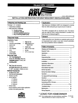
INSTALLATION EXAMPLES
Bedrooms
Fresh Air
Exhaust Air
Central Control - optional
Fresh air to living room
Exhaust CG 4 (4” Adjustable Grill)
FEL 4 (4” Miter Elbow)
Bathroom
460 mm
3m
HRV
Example diagram only - Duct configuration may change depending on model
Fully Dedicated System - RECOMMENDED
(New Construction)
NOTES:
1. Stale air is drawn from key areas of the home (bathroom, kitchen,
laundry room).
2. Fresh air is distributed through habitable rooms in the house (bed-
rooms, living room).
3. The HRV's airflow must be balanced on site using the procedure
found in section "AIRFLOW BALANCING"

10
Bedrooms
Fresh Air
Exhaust Air
Furnace thermostat
Exhaust CG 4 (4” Adjustable Grill)
Bathroom
460 mm
HRV
Central Control - optional
Return Air
HRV
Connection
3m
Partially Dedicated System
DIRECT CONNECTION of the SUPPLY AIR STREAM to the FURNACE COLD AIR RETURN
(Stale air drawn from key areas of home)
NOTES:
1. Furnace blower must operate when ventilation from HRV is required.
The furnace should be set to run continuously or interlocked with HRV.
2. Weatherhood arrangement is for illustrative purposes only. 3m (10')
minimum separation and 460mm (18") above grade is recommended.
3. Due to the differences in pressure between the HRV and the equip-
ment it is being connected to, the HRV's airflow must be balanced on
site, using the procedure found in section “AIRFLOW BALANCING”.
FEL 4 (4” Miter Elbow)
INSTALLATION EXAMPLES (CONT'D)
Example diagram only - Duct configuration may change depending on model
HRV/Furnace ducting for Partially Dedicated System
Stale air coming from different areas of the
house (ie bathroom, kitchen).
* Unit air flow should be balanced while HRV is on "High" speed and fur-
nace blower is running.
Outside
Air return
1 m (3' 3")
min.
recommended
Cold air
return
* Ductwork layout may dif-
fer depending on model

11
INSTALLATION EXAMPLES (CONT'D)
DIRECT CONNECTION of both the HRV SUPPLY AIR STREAM and
EXHAUST AIR STREAM to the FURNACE COLD AIR RETURN
Simplified Installation
Option 1
(Return/Return Method)
NOTES:
1. Furnace blower must operate when ventilation from HRV is required.
The furnace should be set to run continuously or interlocked with HRV.
2. A minimum separation of 1m (39") is recommended between the two
direct connections.
3. In order to prevent exhausting any fresh air, the HRV's exhaust air con-
nection should be upstream of the HRV's supply air connection when
ducting to the furnace's cold air return.
4. Weatherhood arrangement is for illustrative purposes only. 3m (10') mini-
mum separation and 460mm (18") above grade is recommended.
5. Due to the differences in pressure between the HRV and the equipment
it is being connected to, the HRV’s airflow should be balanced on site,
using the procedure found in section "AIRFLOW BALANCING".
NOTE: In the case of a sim-
plified installation, Option 1
is recommended.
Example diagram only - Duct configuration may change depending on model
Stale air coming from different areas of the
house (ie bathroom, kitchen).
* Unit air flow should be balanced while HRV is on "High" speed and fur-
nace blower is running.
Outside
Air return
1 m (3' 3")
min.
recommended
Cold air
return
* Ductwork layout may dif-
fer depending on model
HRV/Furnace ducting for Simplified Installation - Option 1

12
DIRECT CONNECTION of both the HRV SUPPLY AIR STREAM &
EXHAUST AIR STREAM to the FURNACE COLD AIR RETURN & SUPPLY AIR SIDE
Simplified Installation
Option 2
(Supply/Return Method)
NOTES:
1. Furnace blower must operate when ventilation from HRV is required.
The furnace should be set to run continuously or interlocked with HRV.
2. The exhaust air connection should be upstream of the supply air con-
nection to prevent exhausting any fresh air.
3. Weatherhood arrangement is for illustrative purposes only. 3m (10')
minimum separation and 460mm (18") above grade is recommended.
4. Due to the differences in pressure between the HRV and the equip-
ment it is being connected to, the HRV‘s airflow must be balanced on
site, using the procedure found section "AIRFLOW BALANCING".
INSTALLATION EXAMPLES (CONT'D)
NOTE: In the case of a sim-
plified installation, Option 1
is recommended.
Stale air coming from different areas of the
house (ie bathroom, kitchen).
* Unit air flow should be balanced while HRV is on "High" speed and fur-
nace blower is running.
Outside
Air return
1 m (3' 3")
min.
recommended
Cold air
return
* Ductwork layout may dif-
fer depending on model
HRV/Furnace ducting for Simplified Installation - Option 2
Example diagram only - Duct configuration may change depending on model
/