
www.furuno.com
All brand and product names are trademarks, registered trademarks or service marks of their respective holders.
Installation Manual
COLOR SECTOR SCANNING SONAR
Model CH-37BB
SAFETY INSTRUCTIONS ................................................................................................ i
SYSTEM CONFIGURATION .......................................................................................... iii
EQUIPMENT LISTS........................................................................................................ iv
1. MOUNTING..............................................................................................................1-1
1.1 Hull Unit .............................................................................................................................1-1
1.2 Transceiver Unit.................................................................................................................1-9
1.3 Processor unit....................................................................................................................1-9
1.4 Monitor.............................................................................................................................1-10
1.5 Motion Sensor..................................................................................................................1-10
1.6 Clinometer........................................................................................................................1-10
2. WIRING....................................................................................................................2-1
2.1 Wiring Among Units ...........................................................................................................2-1
2.2 Synchronizing Transmission with Echo Sounder or Other Sonar ......................................2-2
3. ADJUSTMENTS ......................................................................................................3-1
3.1 General Checks .................................................................................................................3-1
3.2 Adjustment of Transceiver Unit..........................................................................................3-2
3.3 Heading Alignment.............................................................................................................3-3
3.4 Adjustment of Motion Sensor and Clinometer ...................................................................3-3
3.5 LEDs Status.......................................................................................................................3-4
3.6 Monitor Size Setting...........................................................................................................3-7
3.7 Soundome Painting............................................................................................................3-8
4. SYSTEM MENU.......................................................................................................4-1
APPENDIX 1 JIS CABLE GUIDE .............................................................................AP-1
PACKING LISTS ......................................................................................................... A-1
OUTLINE DRAWINGS ................................................................................................ D-1
INTERCONNECTION DIAGRAMS.............................................................................. S-1

The paper used in this manual
is elemental chlorine free.
・FURUNO Authorized Distributor/Dealer
9-52 Ashihara-cho,
Nishinomiya, 662-8580, JAPAN
A
:
MAR
2012
.
Printed in Japan
All rights reserved.
C1
:
JUL
.
22, 2015
Pub. No.
IME-13370-C1
(
ETMI
)
CH-37BB
0 0 0 1 7 1 8 1 1 1 2

i
SAFETY INSTRUCTIONS
WARNING
Indicates a condition that can cause death or serious
injury if not avoided.
CAUTION
Indicates a condition that can cause minor or moderate
injury if not avoided.
Warning, Caution
Mandatory Action
Prohibitive Action
Read these safety instructions before you operate the equipment.
WARNING
ELECTRICAL SHOCK HAZARD
WARNING
Install the specified transducer
tank in accordance with the
installation instructions. If a
different tank is to be installed the
shipyard is solely responsible for
its installation, and it should be
installed so the hull will not be
damaged if the tank strikes an
object.
The tank or hull may be damaged if
the tank strikes an object.
I
f a steel tank is installed on a
wooden or FRP vessel, take
appropriate measures to prevent
electrolytic corrosion.
Electrolytic corrosion can damage
the hull.
Be sure that the power supply is
compatible with the voltage rating
of the equipment.
Connection of an incorrect power
supply can cause fire or equipment
damage. The voltage rating of the
equipment appears on the label
above the power connector.
Turn off the power at the switch-
board before beginning the instal-
lation.
Fire or electrical shock can result if
the power is left on.
Do not install the equipment where
it may get wet from rain or water
splash.
Water in the equipment can result in
fire, electrical shock or equipment
damage.
Be sure no water leaks in at the
transducer installation site.
Water leakage can sink the vessel.
Also confirm that the transducer will
not loosen by ship's vibration. The
installer of the equipment is solely
responsible for the proper installation
of the equipment. FURUNO will
assume no responsibility for any
damage associated with improper
installation.
Only qualified personel
should work inside the
equipment.
Do not open the equipment
unless totally familiar with
electrical circuits and
service manual.

SAFETY INSTRUCTIONS
ii
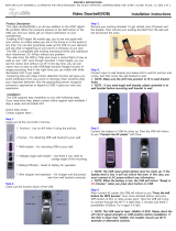
Transceiver unit
Standard
compass
1.50 m 0.95 m
WORKING WITH THE SONAR OIL
Precautions
-
Keep oil away from eyes. Wear protective
gloves when working with the oil. The oil
can cause inflammation of the eyes.
-
Do not touch the oil. Wear protective
gloves when working with the oil. The oil
can cause inflammation of the skin.
-
Do not ingest the oil. Diarrhea or vomiting
can result.
-
Keep the oil out of reach of children.
Emergency
-
If the oil enters eyes, flush with clean
water about 15 min. Consult a physician.
-
If the oil contacts skin, wash with soap
and water.
-
If the oil is ingested, see a physician
immediately.
Disposal of oil and its container
Dispose of oil and its container in accord-
ance with local regulations. For further
details, contact place of purchase.
Storage
Seal container to keep out foreign
material. Store in dark place.
Steering
compass
Observe the following compass safe
distances to prevent deviation of a
magnetic compass:
CAUTION
Ground the equipment to
prevent electrical shock and
mutual interference.

iii
SYSTEM CONFIGURATION
PROCESSOR UNIT
CH-371
MONITOR 䋨XGA/SXGA,
PORTRAIT TYPE, LOCAL SUPPLY)
NAV EPUIPMENT
NAV EQUIPMENT/
CURRENT IND.
RECTIFIER
RU-3423
LOUD SPEAKER
CA-150BS-ASSY
TRANSCEIVER
CH-341
HULL UNIT
CH-342
REMOTE CONTROL
CH-343
MOTION SENSOR
MS-100
OR
CLINOMETER
BS-704
AC100/110/
220V, 1ø
50/60Hz
DPYCY-1.5
DPYCYS-1.5
06S4061
5m,
ø
22
DPYCYS-1.5
5m
06S4037, 10m,
ø
9
MJ-A6SPF0012,
5/10m, ø6
CO-0.2x5P,
5/10/15/20m
06S4076
15/30/50m, ø12.5
DC24V
RECTIFIER
RU-1746B-2
AC100/110/
220V, 1ø
50/60Hz
DPYCY-1.5
DPYCYS-1.5
DC24V
CO-0.2X5P: CO-SPEVV-SB-C 0.2x5P,ø13.5

iv
EQUIPMENT LISTS
Standard Supply
Optional Supply
Name Type Code No. Qty Remarks
Control unit CH-371 - 1
Transceiver unit CH-341 - 1 60/113/162 kHz, select one
Hull Unit CH-342 - 1 60/113/162 kHz, 24 VDC,
Shaft length 1.17/2.2/3.8 m
Installation
materials
CP06-01100 000-068-457 Select
one
Cable length: 15 m (standard supply)
CP06-01110 000-068-458 Cable length: 30 m
CP06-01120 000-068-459 Cable length: 50 m
CP06-01102 006-563-250 1 set For control unit
Name Type Code No. Remarks
Remote control CH-343 -
Motion sensor MS-100 -
Clinometer BS-704 -
Rectifier RU-1746B-2 000-030-439 100/110/220 VAC
Rectifier RU-3423 000-030-443 100/110/220 VAC
Loudspeaker CA-150BS-ASSY 000-190-183 8Ω
Fairing 06-021-4502 001-159-790 For an FRP ship
Cable assembly MJ-A6SPF0012-050C 000-154-053 64S4071-2, 5 m, 6 pin-6 pin
MJ-A6SPF0012-100C 000-154-037 64S4071-2, 10 m, 6 pin-6 pin
MJ-A6SPF0011-050C 000-159-690 03S9202-2, 5 m, 6 pin-4 pin
MJ-A6SPF0011-100C 000-159-691 03S9202-2, 10 m, 6 pin-4 pin
5-pair twisted cable CO-SPEVV-SB-C
0.2 x 5P
000-560-451 5 m
000-560-452 10 m
000-560-417 15 m
000-103-868 20 m
48-core cable 06S4056 000-126-160 For extension of cable between
hull unit and transceiver unit,
specify length

EQUIPMENT LISTS
v
Hull Unit
Name Type Code No. Remarks
Steel retraction tank 06-007-1570-2 600-715-702 1.0 m
SHJ-0001-2 661-000-012 1.8 m
06-007-1571-2 600-715-712 3.5 m
FRP retraction tank SHJ-0022 661-000-220 1 m
06-007-1573-0 600-715-730 1.8 m
Aluminum retraction
tank
OP10-5 000-019-283 1 m, with inst. materials
Raise/lower driving
unit
CH-3422-60-2 006-547-010 60 kHz
CH-3422-113/115-2 006-547-050 113 kHz
CH-3422-162-2 006-547-070 162 kHz
Shaft 06-008-1021-1 ROHS 100-028-501 1.17 m
SHJ-0006-2 ROHS 661-000-062 2.2 m
06-007-1572-1 ROHS 600-715-721 3.8 m
Soundome CH-3422-60-11 006-547-090 2.7 m cable (standard)
CH-3422-113/115-11 006-547-150
CH-3422-162-11 006-547-180
CH-3422-60-22 006-547-100 3.7 m cable (option)
CH-3422-113/115-22 006-547-160
CH-3422-162-22 006-547-190
CH-3422-60-38 006-547-110 5.3 m cable (option)
CH-3422-113/115-38 006-547-170
CH-3422-162-38 006-547-200

EQUIPMENT LISTS
vi
This page is intentionally left blank.

1-1
1. MOUNTING
1.1 Hull Unit
General mounting considerations
• Noise and air bubbles will affect performance.
• Keep the transducer away from oil. Oil can corrode the cable.
• Do not expose the transducer to hot water. Hot water can damage the transducer.
• Do not turn on the equipment with the transducer exposed to air. Exposing the
transducer to air may damage it.
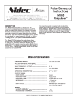
Installation position considerations
Discussion and agreement are required with the dockyard and ship owner in deciding
the location for the hull unit. When deciding the location, take into account the follow-
ing points:
• Select an area where propeller noise, cruising noise, bubbles and interference from
turbulence are minimal. Generally, the point at 1/3 to 1/2 of the ship’s length from
the bow or near the keel is the best. On-the-keel installation is advantageous for
minimizing oil consumption in comparison with off-the-keel. If the hull unit cannot be
installed on the keel, the center of the retraction tank should be within 1 meter of the
keel to prevent a rolling effect.
• Select a place where interference from the transducers of other sounding equip-
ment is minimal. The hull unit should be at least 2.5 meters away from the transduc-
ers of other sounding equipment.
• An obstacle in the fore direction not only causes a shadow zone but also aerated
water, resulting in poor sonar performance. Be sure to locate the transducer well
away from any obstacle in the fore direction.
NOTICE
Do not apply paint, anti-corrosive sealant
or contact spray to coating or plastic
parts of the equipment.
Those items contain organic solvents that
can damage coating and plastic parts,
especially plastic connectors.
1/2
1/3
Within 1 m

1. MOUNTING
1-2
Mounting method
A typical mounting method is shown in the outline drawing at the back of this manual.
Consult ship’s owner, dockyard and user to determine appropriate mounting method.
Pay attention to safety (strength, watertightness) first, followed by ease of mainte-
nance and inspection.
Tank length
Shorten the transducer tank so the transducer is low-
ered into water as deep as possible.
Pay particular attention to the tank length (Lt). Deter-
mine the length of the main shaft as described in the
paragraph.
Note 1: Do not shorten the 1 meter retraction tank.
Shortening it may also necessitate shortening of the
top part of the main shaft, thereby destroying the wa-
tertight construction of the 1.17 meter shaft.
Note 2: When the retraction tank is constructed local-
ly, finish it so that welding beads do not protrude on
the inner surface of the tank. The tank guide will hit
the bead, burning out the raise/lower motor. Also, do
not position the welding bead in the ship’s fore-aft
line.
Note 3: Use of other manufacturer’s tank is permit-
ted. However, the dimensions should be the same as
those in the transducer tank outline drawing.
Mounting of transducer tank
Install the transducer tank referring to the hull unit out-
line drawings at the back of thismanual.
Note: Locate one of the bolt holes 10° to port to mini-
mize mechanical shock at the raise/lower block during
pitching and rolling.
Cable gland
Washer
Gasket
Main shaft
(1.17 m)
Welding bead
Wealding bead
Tank guide
10°

1. MOUNTING
1-3
Assembling and mounting of hull unit
The hull unit is shipped disassembled as the parts. Assemble the hull unit as shown
in the procedure below.
Necessary tools
1. Unscrew ten pieces of socket head cap screws with the ball wrench (supplied) to
detach the soundome.
2. Fill the soundome with sonar oil 6 cm below the top of the dome. (Use only the
specified sonar oil. Use of other sonar oils may affect performance.) Reattach the
soundome.
Name Specification Remarks
Wrench For M10 (Hex. size 17 mm)
Wrench For M20 (Hex. size 20 mm)
Pipe Wrench 55 mm
Ball Wrench Hex size 4 mm Supplied with hull unit kit
Rotate 3 or 4 turns by
hand to make sure that
turning mechanisms are
functioning properly.
Socket head cap screw
(10 pcs. M5x30)
Spring washer
NOTE
O-ring
Remove
Apply Kinoruster*.
Soundome
Screw
6 pcs. M5x10
Do not fasten the M5x10 screws
strongly. Oil may leak into the
soundome.
Protective sponge
Do not unfasten two nuts
painted in red.
Unfastening the nuts may
allow water to leak inside,
which can damage the
soundome.
Kinoruster*: Anti-crevice corrosion
sealant (supplied)
NOTE
Sonar oil
5 cm
Frequency (kHz)
60
113
162
Sonar oil 4L
(000-824-033)
Super sonar oil 4L
(000-177-561-10)
No
Yes
Yes
Yes
No
No
Use packing
material to support
soundome.
Ball wrench

1. MOUNTING
1-4
3. Shorten the main shaft by the length of Lt + 110 mm, where Lt is the length of the
retraction tank. When the retraction tank length is 1 meter do not shorten the 1.17
meter main shaft.
4. Fasten the main shaft to the soundome assembly as follows;
a) Attach screw lock nut to main shaft.
b) Fully screw main shaft into the soundome neck, and then unscrew by four
turns. Coat threads with adhesive (HIGH SUPER).
c) Screw in main shaft completely and tighten the lock nut with spanner.
d) Tighten socket-set screw on lock nut.
CAUTION
WORKING WITH THE SONAR OIL
Precautions
· Keep oil away from eyes. Wear protective
glass when working with the oil. The oil
can cause inflammation of the eyes.
· Do not touch the oil. Wear protective
gloves when working with the oil. The oil
can cause inflammation of the skin.
· Do not ingest the oil. Diarrhea or vomiting
can result.
· Keep the oil out of reach of children.
Emergency
· If the oil enters eyes, flush with clean water about
15 minutes. Consult a physician.
· If the oil contacts skin, wash with soap and water.
· If the oil is ingested, see a physician immediately.
Disposal of oil and its container
· Dispose of oil and its container in accordance
with local regulations. For further details, contact
place of purchase.
Storage
· Seal container to keep out foreign material. Store
in dark place.
Lt + 110 mm
Supplied Length: 1.17 m (2.2 m, 3.8 m)
Take care not
to scratch.
Chamfer edge to protect
O-ring from damage.

1. MOUNTING
1-5
e) Fasten two reinforce metal fittings to connect the main shaft and the soun-
dome assembly securely (not using the stopper washer).
5. Clean the main shaft and pass it through the main body flange.
While holding soundome neck with pipe
wrench, tighten lock nut with wrench.
Lock nut
Apply adhesive
Set screw
Reinforcement
metal fittings
Reinforcement metal
fittings
Hex. bolts (M10x100)
Plain washer/Spring
washer/Nut (4 pcs)
Confirm the O-ring
is in position
Main body flange

1. MOUNTING
1-6
6. Set the grease cotton to the main body flange and tighten the grease cotton re-
tainer temporarily.
7. Temporarily fasten the fastening band onto the main shaft at the location shown
below.
8. Inscribe bow mark at the top of the main shaft. Pass pipe clamp through the main
shaft and install washer, gasket and cable gland.
Wind grease cotton onto
main shaft and cut it as
shown below.
Space joint of grease cotton
120° apart and push them into
body flange.
Flat washer
Lt: Tank length
Lt - 430 mm
Fastening band
Pipe clamp
Inscribe bow mark,
referring to the bow mark
on the soundome.
Gasket
Cable gland
Flat washer
Pipe cap
For 2.2/3.8 m shaft
70
3
Tighten cable gland for gap
of approx. 3 mm.
Hold here with
pipe wrench

1. MOUNTING
1-7
9. Fasten the hull unit to the transducer tank, orienting it so the ship’s fore-aft line
crosses the front panel of the raise/lower drive block at an angle of approximately
45 degrees.
10. Install the raise/lower drive block as follows;
a) Rotate the main shaft so the bow mark faces ship's bow.
b) Install the raise/lower drive block onto the main body flange.
c) Fix the main shaft with the shaft retainer.
d) Loosen the fastening band, slide it up to the shaft retainer and fasten it.
e) Check that the distance from the top of the main shaft to the top of the shaft
retainer is as follows:
• 1.17 m main shaft: 75 mm
• Main shaft cut at Lt + 110 mm: 15 mm
Apply Kinoruster.
M20 x 90 (8 pcs)
M20 Flat washer
M20
Flat washer/
Spring washer/
Nut
Outer edges of main
body flange and tank
should be in line with
one another.
Wipe off foreign material.
45°
Bow
CAUTION:
1. Do not drag hull unit on floor.
2. Do not rest hull unit against wall.
Orient the hull unit as above to
minimize shock and vibration on
the raise/lower drive block when
ship is pitching and rolling.

1. MOUNTING
1-8
If not as shown above, loosen shaft retainer and fastening band to adjust the dis-
tance. This will place the bottom of the soundome 10 mm above the bottom of the
retraction tank when the soundome is retracted.
11. Tighten the grease cotton retainer for a gap of 7 to 9 mm.
Checking manual raise/lower of transducer with hand crank
Perform this check after all wiring has been completed. Ship’s mains power must ap-
plied to the hull unit, otherwise the magnetic brake of the raise/lower motor activates,
disabling the manual raise/lower gears.
1. turn off the breaker on the hull unit.
2. Detach the brake-off switch cover.
3. Set hand crank to the shaft gear and turn it while pressing the brake-off switch.
Raise/lower
drive block
Shaft retainer
Bow
mark
Shaft
Trunnion bolt
10 mm
Fastening band
Fasten for a gap of
1 mm approx.
1.17 m shaft: 75 mm
Shortened shaft: 15 mm
7 to 9 mm
Grease cotton retainer
Grease cotton

1. MOUNTING
1-9
4. The transducer should raise/lower smoothly with even force in upper to lower lim-
its. If not, the centers of the main body flange and the retraction tank are not
aligned. Adjust the hull mounting position if necessary.
1.2 Transceiver Unit
Mounting considerations
• The mounting location should be well ventilated and dry.
• The unit can be mounted on a bulkhead or the deck. The unit weights 8.5 kg so re-
inforce the mounting location if necessary.
To install the unit, refer to outline drawing D-2. Secure the maintenance space shown
in the outline drawing for ease of maintenance and service.
1.3 Processor unit
Mounting considerations
Select the mounting location considering the following
conditions:
• Select a location where the processor unit can easily
be operated while observing the fishing ground or
area surrounding the vessel.
• Locate the unit at least 1 meter away from equipment
which contains magnets (radar magnetron, loud-
speaker).
Mounting Procedure
1. Loosen two bolts at front of processor unit and re-
move the chassis from mounting base.
2. Fix the mounting base with six tapping screws φ6 x
20.
3. Put the chassis onto the mounting base.
4. Push the chassis toward the mounting base end.
Breaker
Raise
Lower
Brake Off
switch
Manualy raising/lowering
without connecting ship’s
mains may damage motor.
Loosen these bolts and
separate mounting base.
Processor unit
Mounting base
PWR

1. MOUNTING
1-10
5. Fasten the chassis to mount base with two bolts removed at step 1.
1.4 Monitor
The portrait type monitor MU-151C or a commercial monitor can be used. The MU-
151C is designed to be flush mount in a console.
When a commercial monitor is used, it should meet the following specifications;
• Input signal: Analog RGB separated
• Resolution: XGA (1024 x 768) or SXGA (1280 x 1024), 60 Hz
• Signal level: 0.7 Vp-p, analog positive, Synchronization: TTL level
• Impedance: Video signal: 75 ohm, Horizontal 47 ohm, Vertical 47 ohm
1.5 Motion Sensor
The Motion Sensor MS-100 (option) measures ship’s pitching and rolling angles. It is
free from error caused by ship’s vertical and horizontal motion. Therefore, it can be
installed at any convenient location. However, ship’s semi-permanent inclination due
to loading imbalance cannot be detected. Compensate for this as described in Chap-
ter 3.
Mounting considerations
• Vibration in the mounting area should be
minimal.
• Locate the unit away from areas subject
to water splash.
• The ambient temperature should not ex-
ceed 50°C (122°F).
Mounting procedure
Orient the FORE mark on the unit toward the ship’s bow and mount the unit level to
within 5 degree in all directions.
1.6 Clinometer
The clinometer BS-704 (option) detects ship’s inclination caused by ship’s rolling and
pitching. Its output is used to stabilize the sonar beam against rolling and pitching.
The clinometer measures the inclination of the ship by sensing the direction of gravity
acted on it, therefore when installed on a ship, it should be placed on or near the ro-
tation axes of the ship’s rolling and pitching. If it is placed away, upward from the axes,
the measured value becomes larger than the correct value. On the contrary, if it is
placed below the axes, the measured value becomes smaller. The same can be said
when it is placed far to the left or right from the axes.
FORE
AFT
θ≤ 5°

1. MOUNTING
1-11
The rotation axes of pitching and rolling are theoretically considered to be located on
the level of the ship’s draft and in the center of ship. In other words, it can be said as
follows;
1) Vertical position of the pitching and rolling axes is on the draft level of the ship.
2) Horizontal position of the rolling axes is in the center of ship’s port-stbd line.
3) Horizontal position of the pitching axes is in the center of ship’s fore-aft line.
From 1), 2) and 3) above, the crossing point of the two axes is indicated by the black
dots in below. The clinometer should be mounted as close as possible to this point.
Note 1: The vicinity of the hull unit (on the ship's bottom) is too low and should be
avoided, since the polarity of the measured value is reversed.
Note 2: When it is impossible to install the clinometer on the intersecting point of both
rolling and pitching rotational axes, a special effort should be made to install it at place
where the vertical distance to the intersecting point is minimum.
Note 3: The clinometer should be installed on the horizontal plane.
Note 4: Install the clinometer with the bow mark pointing in toward the ship's bow.
Rolling axis
Pitching axis
Draft
LR/2
LR/2
LR/2
LR
LP/2
LP/2
LP/2
LP

1. MOUNTING
1-12
This page is intentionally left blank.
Page is loading ...
Page is loading ...
Page is loading ...
Page is loading ...
Page is loading ...
Page is loading ...
Page is loading ...
Page is loading ...
Page is loading ...
Page is loading ...
Page is loading ...
Page is loading ...
Page is loading ...
Page is loading ...
Page is loading ...
Page is loading ...
Page is loading ...
Page is loading ...
Page is loading ...
Page is loading ...
Page is loading ...
Page is loading ...
Page is loading ...
Page is loading ...
Page is loading ...
Page is loading ...
Page is loading ...
Page is loading ...
Page is loading ...
Page is loading ...
Page is loading ...
Page is loading ...
Page is loading ...
Page is loading ...
Page is loading ...
Page is loading ...
Page is loading ...
Page is loading ...
-
 1
1
-
 2
2
-
 3
3
-
 4
4
-
 5
5
-
 6
6
-
 7
7
-
 8
8
-
 9
9
-
 10
10
-
 11
11
-
 12
12
-
 13
13
-
 14
14
-
 15
15
-
 16
16
-
 17
17
-
 18
18
-
 19
19
-
 20
20
-
 21
21
-
 22
22
-
 23
23
-
 24
24
-
 25
25
-
 26
26
-
 27
27
-
 28
28
-
 29
29
-
 30
30
-
 31
31
-
 32
32
-
 33
33
-
 34
34
-
 35
35
-
 36
36
-
 37
37
-
 38
38
-
 39
39
-
 40
40
-
 41
41
-
 42
42
-
 43
43
-
 44
44
-
 45
45
-
 46
46
-
 47
47
-
 48
48
-
 49
49
-
 50
50
-
 51
51
-
 52
52
-
 53
53
-
 54
54
-
 55
55
-
 56
56
-
 57
57
-
 58
58


Furuno CH37BB/113 Installation guide
- Type
- Installation guide
- This manual is also suitable for
Ask a question and I''ll find the answer in the document
Finding information in a document is now easier with AI
Related papers
Other documents
-
AHT MEL-1 Installation Instructions Manual
-
Danfoss RTC Rooftop Control Board Installation guide
-
 Wesmar SS590 SERIES Installation & Operation Manual
-
 AT&T digital life YZP-RNCDSW01A User manual
-
Elster Type Retraction tool UT NG Operating instructions
-
 Avtron Unipulser M185 Operating instructions
-
Brunton Download Owner's manual
-
Episode ES-SUB-TRP8-300-BLK Owner's manual
-
-
Aeg-Electrolux SU65040-1E User manual


