Page is loading ...

www.furuno.com
A
ll brand and product names are trademarks, registered trademarks or service marks of their respective holders.
Installation Manual
SEARCHLIGHT SONAR
DUAL-FREQUENCY SEARCHLIGHT SONAR
Model CH-500/CH-600
SAFETY INSTRUCTIONS.............................................................................................................i
SYSTEM CONFIGURATION.......................................................................................................iii
EQUIPMENT LISTS.....................................................................................................................iv
1.MOUNTING............................................................................................................................ 1-1
1.1 Required Tools and Materials..........................................................................................................1-1
1.2 Control/Display Unit (Standalone Type) ..........................................................................................1-2
1.3 Display Unit (Black Box Type).........................................................................................................1-3
1.4 Control Unit (Black Box Type) ........................................................................................................1-6
1.5 Transceiver Unit...............................................................................................................................1-9
1.6 Hull Unit.........................................................................................................................................1-10
1.7 External Monitor.............................................................................................................................1-35
2. WIRING ............................................................................................................................... 2-1
2.1 Control/Display Unit (Standalone Type) ..........................................................................................2-2
2.2 Display Unit (Black Box Type).........................................................................................................2-3
2.3 Control Unit (Black Box Type) ........................................................................................................2-4
2.4 Transceiver Unit...............................................................................................................................2-4
2.5 Hull Unit ..........................................................................................................................................2-7
2.6 Auto Filter ........................................................................................................................................2-9
2.7 Input/Output Sentences (NMEA0183)...........................................................................................2-10
2.8 Input/Output PGNs (NMEA2000)...................................................................................................2-10
3. CHECKING AND INITIAL SETTINGS................................................................................ 3-1
3.1 Check Points After Installation.........................................................................................................3-1
3.2 Language Setting.............................................................................................................................3-2
3.3 Heading Alignment, Draft and Stroke Adjustments .........................................................................3-3
3.4 Checking TX Frequency..................................................................................................................3-5
3.5 Setting for Synchronizing Transmission with other Equipment (External KP) .................................3-6
3.6 Motion Sensor Offset.......................................................................................................................3-6
3.7 Navigation Equipment Setup...........................................................................................................3-8
3.8 System Backup................................................................................................................................3-9
3.9 Color Settings................................................................................................................................3-11
3.10 Automatic adjustment of the train direction....................................................................................3-11
3.11 Decreasing cavitation ....................................................................................................................3-12
APPENDIX 1 JIS CABLE GUIDE....................................................................................... AP-1
APPENDIX 2 HOW TO MAKE THE RETRACTION TANK FOR WOODEN VESSEL....... AP-2
APPENDIX 3 HOW TO INSTALL THE RETRACTION TANK FOR WOODEN VESSEL.. AP-8
PACKING LISTS.......................................................................................................................A-1
OUTLINE DRAWINGS..............................................................................................................D-1
INTERCONNECTION DIAGRAM.............................................................................................S-1

The paper used in this manual
is elemental chlorine free.
・FURUNO Authorized Distributor/Dealer
9-52 Ashihara-cho,
Nishinomiya, 662-8580, JAPAN
A
:
MAR
2017
.
Printed in Japan
All rights reserved.
E
:
APR
.
06, 2018
Pub. No.
IME-13540-E
(
TEHI
)
CH-500/CH-600
0 0 0 1 9 2 2 1 1 1 4

i
SAFETY INSTRUCTIONS
WARNING
WARNING
Do not open the equipment
unless totally familiar with
electrical circuits and service
manual.
Only qualified personnel can work
inside the equipment.
Do not install the equipment in a
dusty environment, or one where the
equipment may get wet from rain or
water splash.
Dust or water in the equipment can
result in fire, electrical shock, or damage
to the equipment.
Turn off the power at the mains
switchboard before beginning the
installation.
Connection of an incorrect power supply
can cause fire or damage the equipment.
Be sure no water leaks in at the
transducer installation site.
Water leakage can sink the vessel. Also
confirm that the transducer will not
loosen by ship’s vibration. The installer
of the equipment is solely responsible
for the proper installation of the
equipment. FURUNO will assume no
responsibility for any damage
associated with improper installation.
Install the specified transducer tank
in accordance with the installation
instructions. If a different tank is to
be installed the shipyard is solely
responsible for its installation, and it
should be installed so the hull will
not be damaged if the tank strikes an
object.
The tank or hull may be damaged if the
tank strikes an object.
The installer must read the applicable safety instructions before attempting to operate or install the
equipment.
Indicates a potentially hazardous situation which, if not avoided,
could result in death or serious injury.
WARNING
Indicates a potentially hazardous situation which, if not avoided,
can result in minor or moderate injury.
CAUTION
Warning, Caution
Prohibitive Action
Mandatory Action
ELECTRICAL
SHOCK
HAZARD

SAFETY INSTRUCTIONS
ii
CAUTION
WORKING WITH THE SONAR OIL
Precautions
• Keep the oil away from eyes. Wear
protective glasses when working with
the oil. The oil can cause inflammation
of the eyes.
• Do not touch the oil. Wear protective
gloves when working with the oil. The
oil can cause inflammation of the skin.
• Do not ingest the oil. Diarrhea or
vomiting can result.
• Keep the oil out of reach of children.
• For further details, see the material
safety data sheet (MSDS).
Emergency
• If the oil enters eyes, flush with clean water
for about 15 min. Consult a physician.
• If the oil contacts skin, wash with soap and
water.
• If the oil is ingested, see a physician
immediately.
• Keep the oil out of reach of children.
• For other information, see the material safety
data sheet (MSDS).
Disposal of oil and its container
• Dispose of oil and its container in
accordance with local regulations. For further
details, contact the place of purchase.
Storage
• Seal container to keep out foreign materials.
Store in dark place.
Ground the equipment to prevent
electrical shock and mutual
interference.
Observe the following compass safe
distances to prevent magnetic
compass deviation:
CAUTION
Keep away from the raise/lower shaft
of the hull unit when it is working.
Injury may result if caught in the shaft.
The transducer tank should be
mounted 100 mm or more above the
waterline. If this is impossible, use a
waterproofing shaft and gland
(supplied locally) and make safety
provisions (ex. construction of
watertight compartment).
If the ambient temperature around the
hull unit will be below 0°C, provide the
sonar compartment with a heater to
keep the temperature above 0°C.
The hull unit can not work if the ambient
temperature is below 0 °C.
If a steel tank is installed on a wooden
or FRP vessel, take appropriate
measures to prevent electrolytic
corrosion.
Electrolytic corrosion can damage the
hull.
Do not apply substances which
contain organic solvents (alcohol,
thinner, etc.) to the soundome.
Chemical cracking may occur.
Do not connect/disconnect the
connector while turning the power on.
The equipment may be damaged.
Connect the ground terminal to the
ship’s ground.
If the ground terminal is connected to a
terminal other than the ship’s ground (ex.
main engine), electrolytic corrosion may
occur.
The hull unit is designed to withstand
ship’s speed of 20 kn (15 kn during
raise/lower operation). For vessels with
greater speed, reinforce the hull unit.
Unit
Standard
compass
Steering
compass
MU-121C
CH-502
CH-602
0.75 m
0.55 m
0.55 m
0.50 m
0.35 m
0.35 m
CH-503 1.30 m 0.85 m

iii
SYSTEM CONFIGURATION
Display Unit
MU-121C
External monitor*
(MU-150HD or
market equivalent)
*: XGA only.
Transceiver Unit
CH-503
Rectifier Unit
RU-1746B-2
Loudspeaker
CA-151S-ASSY
Navigational Equipment/
Fish Finder/
Heading Sensor/
Current Sensor/
Water Temp.Sensor
Sonar/
Fish Finder/
Current Sensor
100/110/220/
230 V AC,
1ø, 50/60 Hz
12-24 V DC
Rectifier Unit
RU-1746B-2
Hull Unit
CH-504/505
: Standard supply
: Option or local supply
100/110/220
/230 V AC,
1ø, 50/60 Hz
12/24 V DC
Remote
Controller
CH-256
Remote
Controller
CH-256
KP signal
NMEA0183×2
NMEA2000 Equipment
NMEA2000
Control Unit
CH-502 (CH-500)/
CH-602 (CH-600)
Control Unit
CH-502 (CH-500)/
CH-602 (CH-600)

iv
EQUIPMENT LISTS
Standard Supply
*: Hull unit can be arranged as follows:
Name Type Code No. Qty Remarks
Control/Display
Unit
CH-502/MU-121C -
1
For CH-500, standalone type
CH-602/MU-121C - For CH-600, standalone type
Control Unit
CH-502 -
1
For CH-500, black box type
CH-602 - For CH-600, black box type
Display Unit MU-121C - 1 Supplied for black box type.
Transceiver
Unit
CH-503 - 1
Hull Unit*
CH-504 -
1
400 mm stroke
CH-505 - 250 mm stroke
Installation
Materials
CP06-02100 001-453-960 1 Supplied for standalone type.
CP06-02200 001-471-870 1
Cable between the control unit and
transceiver unit, supplied for black box
type only
CP06-02301 001-456-130 1 For transceiver unit
CP06-02410 000-032-347
1 See page v.
CP06-02420 000-032-348
CP06-02430 000-032-349
CP06-02440 000-032-350
CP06-02450 000-032-351
CP06-02460 000-032-352
CP06-02501 001-468-920 1 For hull unit
Accessories
FP06-01900 000-033-449 1 Supplied for standalone type.
FP06-01800 001-454-080 1
For display unit, supplied for black box
type
FP06-01600 000-032-340 1 For control unit, supplied for black box
type
FP06-01610 000-032-341 1
Spare Parts
SP06-01601 001-456-120 1 For transceiver unit
SP06-01701 001-456-490
1
For hull unit (24 V DC)
SP06-01702 001-478-140 For hull unit (12 V DC)
□ □ □ □ □
Stroke Input voltage
Frequency/
Tank diameter
Shaft length Cable length
4: 400 mm
5: 250 mm
1: 12 VDC
2: 24 VDC
䚷
Frequency Tank diameter
60 : 60 kHz 8 inch
88 : 88 kHz 8 inch
150 : 150 kHz 8 inch
180 : 180 kHz 8 inch
1806 : 180 kHz 6 inch
240 : 240 kHz 8 inch
60153 : 60/153 kHz 8 inch
85215 : 85/215 kHz 8 inch
<Standard>
䚷
Shaft length
Cable length
22-35 : 2.2 m 3.5 m
22-52 : 2.2 m 5.2 m
30-52 : 3.0 m 5.2 m
38-52 : 3.8 m 5.2 m
<Shaft with cable gland>
䚷
Shaft length
Cable length
11-35 : 1.17 m 3.5 m
11-52 : 1.17 m 5.2 m
19-52 : 1.97 m 5.2 m

EQUIPMENT LISTS
v
Hull Unit
Cables for Installation Materials
Name Type Code No. Qty Remarks
Raise/Lower Drive Unit
CH-5041 - 1 400 mm stroke
CH-5051 - 250 mm stroke
Complete Soundome
Assembly
CH-5048 -
1
For 8 inch retraction tank
CH-5046 - For 6 inch retraction tank
Hull Unit Assembly Parts
CH-5081
000-030-337
1
For CH-5048, 1.17/1.97 m soun-
dome shaft, included liquid gasket
000-030-338
For CH-5048, 1.17/1.97 m soun-
dome shaft, without liquid gasket
CH-5082
000-030-339
For CH-5048, 2.2/3.0/3.8 m soun-
dome shaft, included liquid gasket
000-030-340
For CH-5048, 2.2/3.0/3.8 m soun-
dome shaft, without liquid gasket
CH-5061
000-030-341
For CH-5046, 1.17/1.97 m soun-
dome shaft, included liquid gasket
000-030-342
For CH-5046, 1.17/1.97 m soun-
dome shaft, without liquid gasket
CH-5062
000-030-343
For CH-5046, 2.2/3.0/3.8 m soun-
dome shaft, included liquid gasket
000-030-344
For CH-5046, 2.2/3.0/3.8 m soun-
dome shaft, without liquid gasket
Soundome Shaft
06-008-1021 001-237-220
1
1.17 m
06-008-1022 001-458-090 1.97 m
SHJ-0006 001-237-230 2.2 m
06-007-1591 001-261-030 3.0 m
06-007-1572 001-237-210 3.8 m
Type Code No.
Cable between display unit and
transceiver unit
Cable between transceiver
unit and hull unit
Type Length Type Length
CP06-02410 000-032-347
FRU-HDMI-5M-AS
5 m FRU-WH-A-15M 15 m
FRU-CCCAF18-05M-B
CP06-02420 000-032-348
FRU-HDMI-5M-AS
5 m FRU-WH-A-30M 30 m
FRU-CCCAF18-05M-B
CP06-02430 000-032-349
FRU-HDMI-5M-AS
5 m FRU-WH-A-50M 50 m
FRU-CCCAF18-05M-B
CP06-02440 000-032-350
FRU-HDMI-10M-AS
10 m FRU-WH-A-15M 15 m
FRU-CCCAF18-10M-B
CP06-02450 000-032-351
FRU-HDMI-10M-AS
10 m FRU-WH-A-30M 30 m
FRU-CCCAF18-10M-B
CP06-02460 000-032-352
FRU-HDMI-10M-AS
10 m FRU-WH-A-50M 50 m
FRU-CCCAF18-10M-B

EQUIPMENT LISTS
vi
Option
Name Type Code No, Remarks
Control Unit
CH-502 - For CH-500
CH-602 - For CH-600
Display Unit MU-121C -
Remote Controller CH-256 -
Loudspeaker CA-151S-ASSY -
Rectifier RU-1746B-2 -
Bracket Assem-
bly with Knobs
OP06-24 001-458-030 For desktop mount of display unit
Flush Mount Kit
(DISP)
OP06-25 001-458-040 For flush mount of display unit
Flush Mount Kit
(CTRL)
OP06-26 001-458-050 For flush mount of control unit
Waterproof
Attachment Kit
OP06-27 001-458-060 For soundome shaft
Fixing Materials OP10-9 006-990-040 For remote controller
Cable Assembly
MJ-A10SPF0002-015+ 001-122-610-10
Cable between display unit and
control unit, 1.5 m
MJ-A10SPF0002-050+ 001-122-630-10
Cable between display unit and
control unit, 5 m
MJ-A6SPF0011-050C 000-159-690-10
For
NMEA0183
connection
6 pin-4 pin, 5 m
MJ-A6SPF0011-100C 000-159-691-10 6 pin-4 pin, 10 m
MJ-A6SPF0011-200C 001-244-120 6 pin-4 pin, 20 m
MJ-A6SPF0012-050C 000-154-053-10 6 pin-6 pin, 5 m
MJ-A6SPF0012-100C 000-154-037-10 6 pin-6 pin, 10 m
MJ-A6SPF0012-150C 000-161-513-10 6 pin-6 pin, 15 m
MJ-A6SPF0012-200C 001-244-130 6 pin-6 pin, 20 m
M12-05BM+05BF-010 001-105-750-10
For
NMEA2000
connection
w/micro type
connectors, 1 m
M12-05BM+05BF-020 001-105-760-10
w/micro type
connectors, 2 m
M12-05BM+05BF-060 001-105-770-10
w/micro type
connectors, 6 m
M12-05BFFM-010 001-105-780-10
w/micro type
connector, 1 m
M12-05BFFM-020 001-105-790-10
w/micro type
connector, 2 m
M12-05BFFM-060 001-105-800-10
w/micro type
connector, 6 m
FRU-NMEA-PMM-01 001-471-560 For connecting NMEA2000 cable
FRU-CCCAF18-05M-B 001-471-470
Cable between display unit and
transceiver unit, 5 m
FRU-CCCAF18-10M-B 001-471-480
Cable between display unit and
transceiver unit, 10 m
FRU-HDMI-5M-AS 001-471-490
Cable between display unit and
transceiver unit, 5 m
FRU-HDMI-10M-AS 001-471-500
Cable between display unit and
transceiver unit, 10 m

EQUIPMENT LISTS
vii
Cable for External
Monitor
HDMI-TO-DVI-A-L=5.3M 001-471-450
For connecting external monitor,
5.3 m
HDMI-TO-DVI-A-L=10.3M 001-471-440
For connecting external monitor,
10.3 m
Cable for External
KP
FRU-WH-B-05M 001-471-570 For external KP connection, 5 m
FRU-WH-B-10M 001-471-580 For external KP connection, 10 m
Cable between
Transceiver and
Control
MJ-A10SPF0022-050+ 001-471-540 For sub control unit connection, 5 m
MJ-A10SPF0022-100+ 001-471-550
For sub control unit connection,
10 m
Speaker
Extension Cable
S06-9-5 006-556-270
Extension cable for loudspeaker, 5
m
Tabletop Mount
Kit (CTRL)
FP06-01601 001-458-100 For desktop mount of control unit
Faring 06-021-4502 001-159-790-10 For an FRP ship
Retraction Tank
06-007-1570-2 001-428-120 Steel, 1 m, tank diameter: 8 inch
SHJ-0001-2*1.8M*ROHS 001-428-150 Steel, 1.8 m, tank diameter: 8 inch
06-007-1571-2 001-241-270 Steel, 3.5 m, tank diameter: 8 inch
06-021-4024-0 001-352-280 FRP, 1 m, tank diameter: 8 inch
06-007-1573-0 001-428-260 FRP, 1.8 m, tank diameter: 8 inch
OP10-5 000-019-283
Aluminum, 1 m, tank diameter: 8
inch
06-013-2501 001-241-280 Steel, 1 m, tank diameter: 6 inch
06-013-2502 001-428-130 Steel, 1.8 m, tank diameter: 6 inch
06-013-2503 001-428-140 Steel, 3.5 m, tank diameter: 6 inch
06-022-2201 100-306-180-10 FRP, 1 m, tank diameter: 6 inch
06-022-2202 100-306-200-10 FRP, 1.8 m, tank diameter: 6 inch
Name Type Code No, Remarks

EQUIPMENT LISTS
viii
This page is intentionally left blank.

1-1
1. MOUNTING
1.1 Required Tools and Materials
Prepare the following tools in advance for this installation.
No. Name Qty Specification/Remarks
1
Phillips-head
Screwdriver
- #1 for M3 and #2 for M4/M5
2 Wrench -
For M4 (hex. size 7 mm), M8 (hex. size 13 mm), M10 (hex. size
17 mm), M16 (hex. size 24 mm, for CH-5046), M20 (hex. size 30
mm, for CH-5048)
3 Adjustable Wrench - Hex. size 35 mm and 41 mm
4 Pipe Wrench - Hex. size 55 mm
5
Ball Wrench*
1
- For M5 (hex. size 4 mm)
6 Ratchet Wrench 1 Hex. size 19 mm, for checking manual raise/lower of transducer
7 Hex Wrench 1
Hex. size 3 mm, only required for optional waterproofing attach-
ment kit (OP06-27)
8
Terminal Opener*
2
- For wiring WAGO connector
9 Power Cable
1 DPYCYSLA-2.5 cable, for hull unit
1 DPYCY-2.5 cable, for transceiver unit
10 Ground Wire 4 IV-2sq., for hull unit, transceiver unit, display unit, control unit
11 Crimp-on Lug 4 FV2-4, for ground wire
12 Vinyl Tape - For fabricating
13 Heat Shrinkable Tube - For drain wire of the DPYCYSLA-2.5 cable
14 Lithium Grease -
Recommended:
• Daphne Eponex Grease No.2 (IDEMITSU KOSAN CO.,LTD)
• Shell Albania Grease S No.2 (SHOWA SHELL SEKIYU K. K.)
• Mobilux EP No.2 (Exxon Mobil Corporation)
• Multinox Grease No.2 (Nippon Oil Corporation)
15
Liquid Gasket*
3
- TB1121 or TB1184 (ThreeBond Holdings Co., Ltd.)
16 Retaining Compound -
For optional waterproof attachment kit (OP06-27)
Recommended: LOCTITE 601 (Henkel.,LTD)
17 Extension Cable -
Used only when the raise/lower control unit is mounted separately
(not recommended).
Cable diameter: 7±0.5 mm
*
1
:
Supplied with installation materials for the CH-5048. Not required for CH-5046.
*
2
:
Pre-attached inside the raise/lower control unit.
*
3
:
Liquid gasket may not be supplied with the product because of export restrictions
in each country. If not included, prepare specified liquid gasket locally.
NOTICE
Do not apply paint, anti-corrosive sealant or contact
spray to coating or plastic parts of the equipment.
Those items contain organic solvents that can damage
coating and plastic parts, especially plastic connectors.

1. MOUNTING
1-2
1.2 Control/Display Unit (Standalone Type)
There are two configurations for control unit and display unit installation; standalone
or black box type. Desktop mount is available for standalone type.
For how to install the control unit and display unit separately, see section 1.3 (display
unit) and section 1.4 (control unit).
Mounting consideration
Select a mounting location, keeping in mind the following points:
• Select a location where the unit can easily be operated.
• Keep the display unit out of direct sunlight.
The LCD can blackout if the unit is exposed to the direct sunlight for a long time.
• Locate the unit away from places subject to water splash and rain.
• Locate the unit away from exhaust pipes and ventilators.
• The mounting location should be well ventilated.
• Select a location where shock and vibration are minimal.
• Referring to the outline drawings at the back of this manual, allow sufficient space
for maintenance and service.
• Select a mounting location considering the length of the cables to be connected to
the unit.
• A magnetic compass will be affected if the unit is placed too close to the magnetic
compass. Observe the compass safe distances at the front of this manual to prevent
interference to a magnetic compass.
Procedure
1. Secure the supplied bracket to the mounting location, using four supplied self-tap-
ping screws (520).
2. Fasten two supplied knobs to the control/display unit loosely.
Knob
(2 pcs)
Self-tapping screw
(Ø5×20, 4 pcs)
Bracket
Control/display unitControl/display unit

1. MOUNTING
1-3
3. Connect the cables to the control/display unit, referring section 2.1.
Note: Place the unit face-down on a soft, clean surface to prevent the damage to
the LCD.
4. Set the unit in the bracket, then fasten the knobs.
1.3 Display Unit (Black Box Type)
The display unit can be mounted on a desktop or flush mounted in a console. Follow-
ing optional item is required for each mounting method.
• Desktop mounting: Bracket assembly with knobs (OP06-24)
• Flush mounting: Flush mount kit (OP06-25)
Mounting consideration
Select a mounting location, keeping in mind the following points:
• Keep the display unit out of direct sunlight.
The LCD can blackout if the unit is exposed to the direct sunlight for a long time.
• Locate the unit away from places subject to water splash and rain.
• Locate the unit away from exhaust pipes and ventilators.
• The mounting location should be well ventilated.
• Select a location where shock and vibration are minimal.
• Referring to the outline drawings at the back of this manual, allow sufficient space
for maintenance and service.
• Select a mounting location considering the length of the cables to be connected to
the unit.
• A magnetic compass will be affected if the unit is placed too close to the magnetic
compass. Observe the compass safe distances at the front of this manual to prevent
interference to a magnetic compass.
1.3.1 Desktop mounting
Prepare the optional bracket assembly with knobs (type: OP06-24, code no,: 001-458-
030), to mount the display unit on a desktop. The items included in OP06-24 are listed
in the following table.
Name Type Code No. Qty
Fixing Bracket 06-027-1508-1 100-409-371-10 1
Bracket FP06-01901 001-478-130 1
Bracket Washer 05-029-0132-1 100-087-911-10 2
Knob 19-028-2073-1 100-340-481-10 2
Binding Screw M410 C2700W MBCR2 000-163-543-10 4
Self-tapping Screw 520 SUS304 000-162-608-10 4

1. MOUNTING
1-4
Procedure
1. Secure the bracket to the mounting location, using four self-tapping screws
(520).
2. Secure the fixing bracket to the display unit, using four binding screws (M410).
Note: Place the unit face-down on a soft, clean surface to prevent the damage to
the LCD.
3. Fasten two knobs and bracket washers to the fixing bracket loosely.
4. Connect the cables to the unit, referring section 2.2.
Self-tapping screw
(Ø5×20, 4 pcs)
Bracket
Binding screw
(M4×10, 4 pcs)
Display unit
Fixing bracket

1. MOUNTING
1-5
5. Set the unit in the bracket, then fasten the knobs.
1.3.2 Flush mounting
Prepare the optional flush mount kit (type: OP06-25, code no,: 001-458-040) for flush
mounting the display unit. The included items in OP06-25 are listed in the following
table.
1. Make a mounting hole in the mounting location, referring to the outline drawing at
the back of this manual.
2. Secure the flush mount assembly to the display unit, using four binding screws
(M410).
Note: Place the unit face-down on a soft, clean surface to prevent the damage to
the LCD.
Name Type Code No. Qty
Flush Mount Assembly OP06-25-1 001-454-100 1
Binding Screw M410 C2700W MBCR2 000-163-543-10 4
Self-tapping Screw 520 SUS304 000-162-609-10 4
Knob
(2 pcs)
Bracket washer
(2 pcs)
Binding screw
(M4×10, 4 pcs)
Flush mount
assembly

1. MOUNTING
1-6
3. Connect the cables to the unit, referring section 2.2.
4. Set the unit to the mounting hole, then secure the unit with four self-tapping
screws (520).
1.4 Control Unit (Black Box Type)
The control unit can be mounted on a desktop or flush mounted in a console. The fol-
lowing optional items are required for each mounting method.
• Desktop mounting: Tabletop mount kit* (FP06-01601)
*: Supply depends on configuration purchased.
• Flush mounting: Flush mount kit (OP06-26)
Mounting consideration
Select a mounting location, keeping in mind the following points:
• Select a location where the unit can easily be operated.
• Locate the unit away from places subject to water splash and rain.
• Locate the unit away from exhaust pipes and ventilators.
• The mounting location should be well ventilated.
• Select a location where shock and vibration are minimal.
• Referring to the outline drawings at the back of this manual, allow sufficient space
for maintenance and service.
• Select a mounting location considering the length of the cables to be connected to
the unit.
• A magnetic compass will be affected if the unit is placed too close to the magnetic
compass. Observe the compass safe distances at the front of this manual to prevent
interference to a magnetic compass.
Self-tapping screw
(Ø5×20, 4 pcs)
Mounting hole
Mounting hole

1. MOUNTING
1-7
1.4.1 Desktop mounting
Prepare the optional tabletop mount kit* (type: FP06-01601, code no: 001-458-100)
for flush mounting the display unit. The items included in FP06-01601 are listed in the
following table.
*: Supply depends on configuration purchased.
Procedure
1. Secure the control mounting base to the mounting location, using two self-tapping
screws (520).
2. Fasten two hex. head slot bolts (M412) loosely to the control mounting base,
passing the bolt and screwdriver through the hole at the top of the mounting base.
3. Secure the control mounting bracket to the control unit, using two hex. head slot
bolts (M412).
4. Connect the cables to the unit, referring section 2.3.
Name Type Code No. Qty
Control Mounting Base 06-027-2541-0 100-409-510-10 1
Control Mounting Bracket 06-021-2112-0 100-281-880-10 1
Self-tapping Screw 520 SUS304 000-162-608-10 2
Cosmetic Plug DP-687 000-165-997-10 2
Hex. Head Slot Bolt M412 SUS304 000-162-939-10 4
Hex. head slot bolt
(M4×12, 2 pcs)
Control mounting
base
Self-tapping screw
(Ø5×20, 2 pcs)
Hex. head slot bolt
(M4×12, 2 pcs)
Control mounting
bracket

1. MOUNTING
1-8
5. Set the control unit to the control mounting base, then tightly fasten the two bolts
that were fastened loosely at step 2.
When you set the control unit, align the two notches on the control unit to the bolts
fastened at step 2.
6. Attach the two cosmetic plugs to the holes at the top of the control mounting base.
1.4.2 Flush Mounting
Prepare the optional flush mount kit (type: OP06-26, code no,: 001-458-050) for flush
mounting the display unit. The included items in OP06-26 are listed in the following
table.
Procedure
1. Make a mounting hole in the mounting location, referring to the outline drawing at
the back of this manual.
Name Type Code No. Qty
Control Fixing Fixture 06-027-2543-0 100-409-520-10 1
Self-tapping Screw 520 SUS304 000-162-609-10 4
Hex. Head Slot Bolt M412 SUS304 000-162-939-10 2
Align these notches to the hex.
head slot bolts.
Cosmetic plug (2 pcs)

1. MOUNTING
1-9
2. Secure the control fixing fixture to the control unit, using two hex. head slot bolts
(M412).
3. Connect the cables to the unit, referring section 2.3.
4. Set the unit to the mounting hole, then secure the unit with four self-tapping
screws (520).
1.5 Transceiver Unit
Mount the transceiver unit on a bulkhead.
Mounting consideration
Select a mounting location, keeping in mind the following points:
• Keep the display unit out of direct sunlight.
• Locate the unit away from places subject to water splash and rain.
• Locate the unit away from exhaust pipes and ventilators.
• The mounting location should be well ventilated.
• Select a location where shock and vibration are minimal.
• Referring to the outline drawings at the back of this manual, allow sufficient space
for maintenance and service.
• Select a mounting location considering the length of the cables to be connected to
the unit.
Hex. head slot bolt
(M4×12, 2 pcs)
Control fixing
fixture
Self-tapping screw
(Ø5×20, 4 pcs)

1. MOUNTING
1-10
• A magnetic compass will be affected if the unit is placed too close to the magnetic
compass. Observe the compass safe distances at the front of this manual to prevent
interference to a magnetic compass.
• Secure the unit so that the cable entrance faces downward.
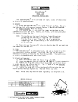
Procedure
1. Drill four pilot holes in the bulkhead for self-tapping screws.
2. Screw two supplied self-tapping screws (520) into the lower pilot holes. Leave
5 mm of thread visible.
3. Set the notches of the unit onto the screws fastened at step 2.
4. Screw two supplied self-tapping screws (520) into the upper fixing holes.
5. Fasten all screws tightly to secure the unit in place.
1.6 Hull Unit
1.6.1 Installation position considerations
Discussion and agreement are required with the dockyard and ship owner in deciding
the location for the hull unit. When deciding the location, take into account the follow-
ing points:
OK
UP
Self-tapping screw
(Ø5×20, 4 pcs)
/