Page is loading ...

COLOR SECTOR SCANNING SONAR
CH-37BB
OPERATOR'S MANUAL
www.furuno.com
Model

The paper used in this manual
is elemental chlorine free.
・FURUNO Authorized Distributor/Dealer
9-52 Ashihara-cho,
Nishinomiya, 662-8580, JAPAN
A
:
MAR
2012
.
Printed in Japan
All rights reserved.
B2
:
MAY
24, 2016
Pub. No.
OME-13370-B2
(
ETMI
)
CH-37BB
0 0 0 1 7 1 7 7 9 1 1

i
IMPORTANT NOTICES
General
• This manual has been authored with simplified grammar, to meet the needs of international us-
ers.
• The operator of this equipment must read and follow the descriptions in this manual. Wrong op-
eration or maintenance can cancel the warranty or cause injury.
• Do not copy any part of this manual without written permission from FURUNO.
• If this manual is lost or worn, contact your dealer about replacement.
• The contents of this manual and equipment specifications can change without notice.
• The example screens (or illustrations) shown in this manual can be different from the screens
you see on your display. The screens you see depend on your system configuration and equip-
ment settings.
• Save this manual for future reference.
• Any modification of the equipment (including software) by persons not authorized by FURUNO
will cancel the warranty.
• All brand and product names are trademarks, registered trademarks or service marks of their
respective holders.
How to discard this product
Discard this product according to local regulations for the disposal of industrial waste. For disposal
in the USA, see the homepage of the Electronics Industries Alliance (http://www.eiae.org/) for the
correct method of disposal.
How to discard a used battery
Some FURUNO products have a battery(ies). To see if your product has a battery, see the chapter
on Maintenance. Follow the instructions below if a battery is used. Tape the + and - terminals of
battery before disposal to prevent fire, heat generation caused by short circuit.
In the European Union
The crossed-out trash can symbol indicates that all types of batteries
must not be discarded in standard trash, or at a trash site. Take the
used batteries to a battery collection site according to your national
legislation and the Batteries Directive 2006/66/EU.
In the USA
The Mobius loop symbol (three chasing arrows) indicates that Ni-Cd
and lead-acid rechargeable batteries must be recycled. Take the used
batteries to a battery collection site according to local laws.
In the other countries
There are no international standards for the battery recycle symbol. The number of symbols can
increase when the other countries make their own recycle symbols in the future.
Cd
Ni-Cd Pb

ii
SAFETY INSTRUCTIONS
Mandatory Action
Prohibitive Action
WARNING
CAUTION
Warning, Caution
The operator must read the safety instructions before attempting to operate the equipment.
Indicates a potentially hazardous situation which, if not avoided,
could result in death or serious injury.
Indicates a potentially hazardous situation which, if not avoided,
could result in minor or moderate injury.
ELECTRICAL SHOCK HAZARD
Do not open the equipment.
Only qualified personel should work
inside the equipment.
Immediately turn off the power at
the switchboard if water leaks into
the equipment or something is
dropped in the equipment.
Continued use of the equipment can
cause fire or electrical shock. Con-
tact a FURUNO agent for service.
WARNINWARNING WARNINWARNING
Immediately turn off the power at
the switchboard if the equipment
is emitting smoke or fire.
Continued use of the equipment can
cause fire or electrical shock.
Contact a FURUNO agent for
service.
Do not disassemble or modify the
equipment.
Fire, electrical shock or serious
injury can result.
Do not place liquid-filled contain-
ers on the top of the equipment.
Fire, electrical shock or serious
injury can result.
Do not operate the equipment
with wet hands.
Electrical shock can result.
Use the proper fuse.
Fuse rating is shown on the equip-
ment. Use of a wrong fuse can
result in damage to the equipment.
Make sure no rain or water splash
leaks into the equipment.
Fire or electrical shock can result if
water leaks in the equipment.
Keep heater away from the equip-
ment.
A heater can melt the equipment’s
power cord, which can cause fire or
electrical shock.

SAFETY INSTRUCTIONS
iii
CAUTION CAUTION
Do not exceed 18 knots when operating
the equipment and do not exceed 15
knots when lowering or raising the
transducer.
The transducer may become damaged.
Do not use the equipment for other than
its intended purpose.
Use of the equipment as a stepping stool,
for example, may result in personal injury
or equipment damage.
A warning label is attached to the equip-
ment. Do not remove the label. If the
label is worn or illegible, contact a
FURUNO agent or dealer.
Disposal of oil and its container
Dispose of oil and its container in accor-
dance with local regulations. For further
details, contact place of purchase.
Precautions
- Keep oil away from eyes. Wear protec-
tive gloves when working with the oil.
The oil can cause inflammation of the
eyes.
- Do not touch the oil. Waer protective
gloves when working with the oil. The oil
can cause inframmation of the skin.
- Do not ingest the oil. Diarrhea or vomit-
ing can result.
- Keep the oil out of reach of children.
Emergency
- If the oil enters eyes, flush with clean
water about 15 minutes. Consult with a
physician.
- If the oil contacts skin, wash with soap
and water.
- If the oil is ingested, see a physician
immediately.
Storage
Seal container to keep out foreign material.
Store in dark place.
Ground the equipment to
prevent electrical shock and
mutual interference.
WORKING WITH THE SONAR OIL
WARNING
⼊䇭๔
To avoid electrical shock, do not
remove cover. No user-serviceable
parts inside.
ᗵ㔚䈱ᕟ䉏䈅䉍䇯
䉰䊷䊎䉴䊙䊮એᄖ䈱ᣇ䈲䉦䊋䊷䉕㐿䈔
䈭䈇䈪ਅ䈘䈇䇯ౝㇱ䈮䈲㜞㔚ㇱಽ䈏
ᢙᄙ䈒䈅䉍䇮ਁ৻䈘䉒䉎䈫ෂ㒾䈪䈜䇯
Name: Warning label (1)
Type: 86-003-1011-3
Code No.: 100-236-233-10
Name: Warning label
Type: 16-021-3517-0
Code No.: 100-350-230-10
ᗵ㔚䈱ᕟ䉏䈅䉍䇯䉰䊷䊎䉴䊙䊮એᄖ
䈱ᣇ䈲䉦䊋䊷䉕㐿䈔䈭䈇䈪ਅ䈘䈇䇯
WARNING
To avoid electrical shock,
do not remove cover.
⼊㩷๔

iv
TABLE OF CONTENTS
FOREWORD ...................................................................................................................vi
SYSTEM CONFIGURATION .........................................................................................vii
1. OPERATIONAL OVERVIEW .................................................................................1-1
1.1 Control Description..................................................................................................... 1-1
1.2 Remote Controller ...................................................................................................... 1-3
1.3 Turning the Power On/Off .......................................................................................... 1-3
1.4 Lowering the Transducer ........................................................................................... 1-4
1.5 Backlight of Panel ...................................................................................................... 1-4
1.6 Presentation Mode ..................................................................................................... 1-4
1.7 Adjusting Gain............................................................................................................ 1-6
1.8 Menu Operation ......................................................................................................... 1-6
2. SONAR MODE .......................................................................................................2-1
2.1 Select Sonar Mode..................................................................................................... 2-1
2.1.1 Standard sonar display .................................................................................. 2-1
2.1.2 Expanded sonar display................................................................................. 2-2
2.2 Basic Operation.......................................................................................................... 2-2
2.3 Selecting Range......................................................................................................... 2-3
2.4 Selecting Sector ......................................................................................................... 2-3
2.5 Setting the Tilt Angle .................................................................................................. 2-4
2.5.1 Tilt angle for surface fish................................................................................ 2-4
2.5.2 How to discriminate fish echoes from the bottom .......................................... 2-4
2.5.3 Suitable tilt angle............................................................................................ 2-5
2.6 R/B and Event Markers (trackball operation) ............................................................. 2-6
2.7 Detecting Schools of Fish Effectively......................................................................... 2-7
2.7.1 Relocating a school of fish for easy observation............................................ 2-7
2.7.2 Suppressing bottom and sea surface reflections ........................................... 2-7
2.7.3 Suppressing bottom tail.................................................................................. 2-7
2.7.4 Displaying surface fish clearly (TVG adjustment) .......................................... 2-7
2.7.5 Detecting schools of fish aurally..................................................................... 2-8
2.8 Rejecting Sonar Interference and Noise .................................................................... 2-9
2.9 Interpreting the Display ............................................................................................ 2-10
2.9.1 How the picture is painted............................................................................ 2-10
2.9.2 Bottom echoes ............................................................................................. 2-10
2.9.3 Schools of fish echo..................................................................................... 2-11
2.9.4 Sea surface reflections................................................................................. 2-11
2.9.5 Wake............................................................................................................ 2-12
2.9.6 False echo by sidelobe ................................................................................ 2-12
2.9.7 Noise and interference................................................................................. 2-12
3. VERTICAL FAN MODE..........................................................................................3-1
3.1 Selecting Vertical Fan Mode ...................................................................................... 3-1
3.2 Basic Operation.......................................................................................................... 3-2
3.3 Selecting Range......................................................................................................... 3-2
3.4 Selecting Bearing for the Vertical Fan........................................................................ 3-3
3.5 Selecting the Display Sector ...................................................................................... 3-4
3.6 Selecting the Sector Center ....................................................................................... 3-4
3.7 Trackball Marker ........................................................................................................ 3-5
3.8 Event Marker..............................................................................................................3-6
3.9 Horizontal/Vertical Marker.......................................................................................... 3-6
3.10 Applying Proper TVG ................................................................................................. 3-7

TABLE OF CONTENTS
v
3.11 Rejecting Interference and Noise ...............................................................................3-7
3.12 Net Mouth Marker.......................................................................................................3-8
3.12.1 How to move the net mouth marker ...............................................................3-9
3.13 Interpreting the Display.............................................................................................3-10
3.13.1 How the picture is painted ............................................................................3-10
3.13.2 Port-stbd picture ...........................................................................................3-10
3.13.3 When ship passes over schools of fish ........................................................3-11
3.13.4 Display of net hauling ...................................................................................3-11
3.13.5 False echo....................................................................................................3-11
4. 3D MODE ...............................................................................................................4-1
4.1 Selecting 3D Display ..................................................................................................4-1
4.2 Turning Vertical Echoes On/Off..................................................................................4-1
4.3 Changing 3D View Scale Mode and Selection...........................................................4-2
4.4 Other Operations ........................................................................................................4-3
5. PRESENTATION MODE .......................................................................................5-1
5.1 Display Combination View..........................................................................................5-1
5.2 Dual Menu ..................................................................................................................5-2
5.3 Description of DUAL Menu.........................................................................................5-2
5.4 E/S Menu....................................................................................................................5-3
6. CUSTOM MODE KEYS .........................................................................................6-1
6.1 Customizing the Keys.................................................................................................6-1
6.2 Using Custom Mode...................................................................................................6-1
6.3 Custom Mode Registration.........................................................................................6-2
6.4 Custom Mode Key Labels ..........................................................................................6-3
7. SYSTEM MENU .....................................................................................................7-1
7.1 How to Display the System Menu...............................................................................7-1
7.2 System Setting Menu .................................................................................................7-2
7.3 Setting Range of Sonar Mode ....................................................................................7-3
7.4 Setting Range of Vertical Fan Mode...........................................................................7-3
7.5 Setting Screen Colors.................................................................................................7-4
7.6 Setting Language .......................................................................................................7-5
7.7 Restoring Default Settings..........................................................................................7-5
8. MAINTENANCE.....................................................................................................8-1
8.1 General Maintenance .................................................................................................8-1
8.2 Maintenance of Transceiver Unit................................................................................8-1
8.3 Fuse Replacement .....................................................................................................8-1
8.4 Maintenance of Hull Unit ............................................................................................8-2
8.5 Processor Unit Test....................................................................................................8-2
8.6 Train/Tilt Test..............................................................................................................8-4
8.7 Test Pattern ................................................................................................................8-4
8.8 Error Messages ..........................................................................................................8-5
8.8.1 Raise lower error message ............................................................................8-5
8.8.2 Transceiver unit error message......................................................................8-5
8.8.3 Speed warning ...............................................................................................8-5
8.8.4 Train error message .......................................................................................8-5
8.8.5 Tilt error message ..........................................................................................8-5
8.9 Troubleshooting..........................................................................................................8-6
APPENDIX 1 MENU TREE ......................................................................................AP-1
SPECIFICATIONS ..................................................................................................... SP-1
INDEX ......................................................................................................................... IN-1

vi
FOREWORD
Congratulations on your choice of the FURUNO CH-37BB Color Sector Scanning Sonar! We are
confident that you will enjoy many years of trouble-free operation with this fine piece of equip-
ment.Since 1948, FURUNO Electric Company has enjoyed an enviable reputation for quality and
reliability throughout the world. This dedication to excellence is furthered by our extensive global
network of agents and dealers.The CH-37BB is the newest addition to FURUNO’s CH family of
sonars. This new sonar is especially designed to provide faster detection capability by sector
scanning method and improved operation by rotary controls and trackball. The sonar picture is
presented in 16 or 8 colors on a high resolution CRT. The excellent signal processing technique
and improved receiver bring you a clear and high-quality picture on the monitor of your choice.We
would appreciate feedback from you, the end-user, about whether we are achieving our purpose.
Thank you for considering and purchasing FURUNO equipment.
Features
• Multi sector scanning provides quick coverage of full 360° area in just 8 transmissions.
• PPI operation can be selected for superior detection range and bottom fish sounding.
• Custom mode keys provide desired sonar settings by one key stroke.
• Selectable background color lessens eye fatigue in both daytime and nighttime operations.
• Selection of frequencies - 60, 113, 162 kHz.
• Trackball offers easy-to-use operation for marker settings.
• Quick training and quick raise/lower operation.
• Vertical mode presents a vertical section of underwater conditions.
• 3D mode shows vertical echoes like a graphic track plotter.

vii
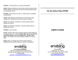
SYSTEM CONFIGURATION
MONITOR
(XGA/SXGA, PORTRAIT TYPE,
LOCAL SUPPLY)
NAV EQUIPMENT
NAV EQUIPMENT
CURRENT INDICATOR
RECTIFIER
RU-3423
TRANSCEIVER UNIT
CH-341
REMOTE CONTROL
CH-343
AC100/110/
220V, 1Ф,
50/60Hz
DPYCY-1.5
DPYCYS-1.5
DPYCYS-1.5
DPYCYS-1.5
O
O
RECTIFIER
RU-1746B-2
AC100/110/
220V, 1Ф,
50/60Hz
DPYCY-1.5
24VDC
24VDC
PROCESSOR UNIT
CH-371
MJ-A6SPF0012
5/10m, Φ6
CO-0.2x5P
5/10/15/20m
SPEAKER
CA-150BS-ASSY
MOTION
SENSOR
MS-100
OR
CLINOMETER
BS-704
06S4061,
5m,Φ22
06S4037,10m,Φ9
06S4076
15/30/50m,Ф12.5
HULL UNIT
CH-342
CO-0.2x5P: CO-SPEVV-SB-C 0.2X5P, Φ13.5

SYSTEM CONFIGURATION
viii
This page is intentionally left blank.

1-1
1. OPERATIONAL OVERVIEW
1.1 Control Description
Main panel
PWR
TRANSDUCER
TRANSDUCER
TRANSDUCER
0
2
4
6
8
10
MODE
RANGE
TRAIN GAIN
SECTOR
TILT
FISHING GROUND
SHING GROUND
ISH
Trackball
123
CUSTOM MODE
ENTER
SECTOR SONAR
Switches on/off
the entire system.
Controls the transducer.
↑: Raises the transducer
↓: Lowers the transducer
Select the detecting range.
FULL
HALF
EVENT
R/B
Adjust the sensitivity of
the receiver.
Controls the tilt angle in the
sonar mode or determines
the sector center of vertical
scanning.
Select the width of the
transducer training sector
among six positions.
Full/half key switches the
training sector or sector width
in full/half circle.
Determines the center bearing
of the train sector or controls
the direction to be off-centered
in the veretical fan mode.
Selects display mode.
Opens the custom mode key
setting menu, which provides
user-defind sonar setting with
a single key.
Controls positions of
range/bearing marker and
event marker on/off.
Pull down the lid of main
panel bottom to show sub
control panel.
Label case

1. OPERATIONAL OVERVIEW
1-2
Sub panel
Sub panel 1
Sub panel 2
Control Description Remark
TVG LEVEL controls the receiver sensitivity to eliminate surface
noise, which may mask shallow targets. TIME determines
the TVG effective range.
2.7.4
NL Reject noise which appears on the screen in light blue or
blue. A setting between 2 and 4 will suffice in most cases.
2.8
AUDIO Adjust the volume of the external loudspeaker, which mon-
itors target echoes.
2.7.5
DIMMER Adjust panel backlighting. 1.5
BRILL Not used
Key Description Remark
HUE Change the background color of the display in the se-
quence of deep blue, blue, black.
7.5
E/S Turn the E/S combination display on/off. (Optional devic-
es required.)
5.1
DEGAUSS Not used
FAST SCAN Change the sector steps (45°/6° in sonar mode and 6°/
3° in vertical fan mode).
2.4
3.5
TRACK Turn the course line plotting on/off. (Navigation equip-
ment required.)
TRANSDUCERTRANSDUCERTRANSDUCER
0
2
4
6
8
10
㪤㪦㪛㪜
㪩㪘㪥㪞㪜
㪫㪩㪘㪠㪥
GAIN
SECTOR
TILT
0
10
0
10
0
10
0
10
0
10
0
10
TVG
LEVEL TIME NL AUDIO
DIMMER BRILL
0
10
0
10
0
10
0
10
0
10
0
10
TVG
LEVEL TIME NL AUDIO
DIMMER BRILL
Sub Panel 1
Sub Panel 2
HUE E/S DEGAUSS
FAST
SCAN
TRACK
MENU
MENU
FULL
HALF
EVENT
R/B
V:H
RANGE
AUTO
TRAIN
BOTTOM MODE
PWR

1. OPERATIONAL OVERVIEW
1-3
1.2 Remote Controller
The Remote Controller CH-343 enables control of the processor unit from a remote
location.
1.3 Turning the Power On/Off
Power on
Press the [PWR] switch on the main panel. The lamp above the switch lights to show
that power is turned on.
Power off
With the ship speed under 15 knots, retract the transducer with the [] key on the main
panel. The lamp above the key lights while the transducer is being raised and goes off
when the transducer fully raised. Then press the [PWR] switch.
Note: The transducer is automatically retracted into the tank even if the [PWR] switch
is pressed before retracting the transducer. However, for safety purpose, make it a
habit to retract the transducer before turning off the power.
V:H RANGE Changes the horizontal range scale in the vertical fan
mode.
3.3
AUTO
TRAIN
Changes the auto and manual train in the vertical fan
mode.
3.4
MENU Displays the menu screen of the mode in use.
Key Description Remark
CH-343CH-343
REMOTE CONTROL
RAISE/
LOWER
MODE
TRAIN
TILT
RANGE
CUSTOM MODE
1 2 3
FULL/HALF
DISPLAY RANGE
Selects Range.
Raise/lower the
transducer.
Select display
mode.
Select fishing
ground.
Tilt angle control/
Select center of
rotation in vertical
scanning.
Select center of
vertical fan mode/
direction of scanning.
Selects the width on
the transducer
training sector.

1. OPERATIONAL OVERVIEW
1-4
1.4 Lowering the Transducer
Press the [] key on the main panel to lower the transducer. The lamp above the key
blinks while the transducer is being lowered and lights when the transducer is fully low-
ered.
1.5 Backlight of Panel
The main and sub panel 1’s backlight can be changed with the dimmer control volume.
Turn clockwise to increase the brightness.
1.6 Presentation Mode
Five presentation modes are available with the MODE control: Normal sonar, Normal
sonar + combination, Expanded sonar, Vertical fan mode or Vertical fan mode + com-
bination and 3D display mode (front and slant perspective views).
Mode Presentation
Normal sonar mode
Normal full circle picture appears on the entire
screen.
Normal sonar, vertical fan of sonar
Normal full circle picture appears at the upper 2/3 of
the screen; vertical fan or sonar on the lower 1/3.
To select the picture to display in the lower 1/3, see
chapter 5.1.
CAUTION
Observe maximum allowable ship's speed of
18 knots during operation and 15 knots while
raising/lowering transducer, to prevent
damage to the transducer.

1. OPERATIONAL OVERVIEW
1-5
Expanded sonar mode
Zoomed picture appears on the entire screen.
Echoes are expanded 1.5 times.
Vertical fan mode
A vertical section of underwater conditions (half-cir-
cle area) appears on the entire screen.
Vertical fan mode + sonar
A vertical section of underwater conditions (half-cir-
cle area) appears on the upper 2/3 and sonar picture
on the lower 1/3. To select the picture to display in
the lower 1/3, see chapter 5.1.
3D display (front perspective view)
The vertical contour line appears historically (time or
distance). Only the latest echo is painted, like the
vertical mode presentation. This mode may be
turned on in the SYSTEM menu.
3D display (slant perspective view)
Display contents are same as front perspective
mode except the perspective is different. This mode
may be turned on in the SYSTEM menu.
Mode Presentation
Own ship's
location
Own ship's
location
Own ship's
location

1. OPERATIONAL OVERVIEW
1-6
1.7 Adjusting Gain
Most equipment malfunctioning claims result from improper setting of switches and
controls. For example, fish, fish habitat or outcrop can not be readily detected by
merely increasing the gain. Initially set the gain between 3 and 5 with the GAIN control.
Then, fine tune depending on the fishing ground, frequency used, etc.
1.8 Menu Operation
1. Press the [MENU] key on the sub panel 2. The MENU window appears.
2. Move the cursor to the top column with [] key.
3. Select the menu required with [] or [] key. The menu items change according
to the menu selected.
4. Select item with [] or [] keys. The selected item is highlighted and the current
setting is circumscribed.
5. Select value with [] or [] keys.
6. Press the [MENU] key again to turn off the menu.
Note: The TX rate is available in 10 levels, 1 to 10. Select “10“ for normal use.
Feeble
echoes
Random
noise
Surface noise
Interference
0
2
46
8
10
Turn GAIN control
clockwise
Turn on “IR” in SONAR
menu
Adjust NL control
0
2
46
8
10
Adjust TVG
control
0
2
46
8
10
Few fish found
or
difficalt to find
fish habitat
Clear Picture!
MENU :
TX RATE :
TX PULSE LENGTH
:
TX OUTPUT POWER
:
TX EXT SYNC :
IR :
STABILIZER :
COLOR :
RES. COLOR :
EXIT: PRESS MENU KEY
SONAR
10
LONG
A
OFF
OFF
OFF
16
LOG
㪙㪦㪫㪫㪦㪤㪆㪊㪛
㪪㪟㪦㪩㪫
㪙
㪦㪥
㪦㪥
㪦㪥
㪏
㪣㪠㪥㪜㪘㪩
㪛㪬㪘㪣 㪜㪆㪪
Cursor
Menu item
㪚㩷㩿㪤㪘㪯㪀
㪪㪨㪬㪘㪩㪜

2-1
2. SONAR MODE
2.1 Select Sonar Mode
Select sonar mode with the MODE switch. The Mode Mark will be a [Full-circle scan-
ning] or [Dome] (half-circle scanning).
Turn the MODE control clockwise/counterclockwise to set the SONAR mode. The so-
nar mode mark appears momentarily.
2.1.1 Standard sonar display
Note: Heading and north mark require current indicator and gyrocompass or log.
320
°
R 100
T 14
°
62 B102°
64
15
→
→
→
Mark for Sonar mod
e
320
°
R 100
T 14
°
㪈㪈㪈
㪉
㪉
㪊
㪊
→
62 B102°
64
15
→
→
→
㪙
→
→
39
40
9
228°
D 35.0
34° 43.261N
135° 20.282E
C1: 0.9
C2: 0.8
C3: 0.5
Ship's bearing
(BOW)
Range
Tilt
Sector center marker (indicated white circle)
Trackball mark
information
Range marker
Bearing marker
Bottom
Fish school echo
Trackball
mark
Trip
(nav data required)
Current data
(current indicator required)
Depth/Lat/Lon
(nav data required)
20
°
T
14
㪉
㪊
Tilt
Fish
school
ech
o
Range marker
Bearing marker
information
㪈㪈
㪉㪉
㪊㪊
Own ship's mark
North
mark
1 to 3:
Current data

2. SONAR MODE
2-2
2.1.2 Expanded sonar display
2.2 Basic Operation
R 150
T 10
°
72 B131°
73
13
→
→
→
Range
Tilt
Sector center (white circle)
Trackball mark
information
Trackball
Own ship's mark
Sector width mark
TRANSDUCERTRANSDUCERTRANSDUCER
0
2
4
6
8
10
MODE
RANGE
TRAIN GAIN
SECTOR
TILT
R/B
FULL
HALF
EVENT
0
10
0
10
0
10
0
10
0
10
0
10
TVG
LEVEL TIME NL AUDIO
DIMMER BRILL
HUE E/S DEGAUSS
FAST
SCAN
TRACK
V:H
TRAIN
AUTO
TRAIN
BOTTOM MODE
MENU
MENU
Turn on/off the power.
Raise/lower the transducer.
Select the mode
to or position.
Select the range desired.
Adjust the gain.
Adjust the tilt angle.
Position the cursor.
Adjust the TVG.
Adjust the noise limitter to
reduce interference.
Open the menu to
adjust the picture, etc.
Set fast scanning.
Set the automatic
training area.
Select the center
position.
Toggle the full-circle
and half-circle mode.
Set the range/bearing marker.
Draw the event mark.
Show the expand
echo display.
PWR

2. SONAR MODE
2-3
2.3 Selecting Range
The RANGE control selects the detection range. Select the range according to either
the fish species being searched or the depth desired. Normally it is set so that the bot-
tom is traced at the lower part of the screen (like an echo sounder).
Note: Unit of range measurement may be changed through the SYSTEM menu. For
details see section 7.1.
2.4 Selecting Sector
Sector width
Sector means the width of the trans-
ducer training. The SECTOR control
selects the training (display) area
among six positions. In the full circle
mode (360°) the direction of training
is clockwise only.
*: Selected by FULL/HALF key
Sector step
The FAST SCAN key in the sub panel 2 selects sector step in 45° or 6°.
Freq. - Range (m) +
Range 60 kHz 50 100 150 ------- 600 800 1200 1600
113 kHz 50 100 150 ------- 500 600 800 1000
162 kHz 50 100 150 ------- 450 500 600 800
Mode Transducer Training Sector (display area)
Sonar mode 45°, 90°, 135°, 180°, 225°*, and 360°*
SEA SURFACE
Sea bed
Range indicated on the screen
R 800
T 8°
Indication of upper-right corner
Trim
Range
Sector center marker
(indicated by a white
circle)

2. SONAR MODE
2-4
2.5 Setting the Tilt Angle
The tilt angle shows the direction to which the sound wave is emitted. When the sound
wave is emitted horizontally, the tilt angle is said to be 0° and when emitted vertically,
90°. To set a tilt angle, operate the TILT control. Watch the tilt angle indication at the
top right corner of the screen. The tilt angle can be set in one-degree steps from +5°
(upward) to 90° (downward).
2.5.1 Tilt angle for surface fish
Sound emitted from the sonar transducer forms an oval-shaped beam with a width of
approximately 11° (for 113 kHz transducer) in the vertical direction (vertical beam
width). The tilt angle is indicated by the angle between the center line of the beam and
the horizontal plane. Then, if the tilt angle is set to 0°, the center line is parallel with
the sea surface and one half of the emitted sound goes upward, toward the sea sur-
face.
This causes one half of the emitted sound to be reflected toward the transducer and
displayed on the screen as sea surface reflections. When the sea is calm, since the
sound is reflected just like a light hitting a mirror at a narrow incident angle, it propa-
gates away and the sea surface reflections become negligible
However if the sea is not calm enough, they will become dominant and interfere with
observation of wanted echoes. To minimize these sea surface reflections and to
search surface schools of fish effectively, the tilt angle is usually set between 5° and
7° so the upper portion of the beam becomes almost parallel with the sea surface.
When the sea is rough, it is often set to a little larger angle.
2.5.2 How to discriminate fish echoes from the bottom
Finding a proper tilt angle is important when searching for fish.
Following figure illustrates how schools of fish are displayed on the screen using three
different tilt angles.
11°
11°
Tilt angle 0°
Tilt angle 5° - 7°
R400
T 15
Tilt angle
CASE 1
㪚㪘㪪㪜㩷㪉
CASE 3
a
a
a
b
/