Debris Kit, STX-38 EFI Stump Grinder

Toro Debris Kit, STX-38 EFI Stump Grinder Installation guide

  • Hello! I am an AI chatbot trained to assist you with the Toro Debris Kit, STX-38 EFI Stump Grinder Installation guide. I’ve already reviewed the document and can help you find the information you need or explain it in simple terms. Just ask your questions, and providing more details will help me assist you more effectively!
  • What parts are included in the Toro Debris Kit?
    How do I replace the muffler guard?
    What steps should I take to install the covers?
    How do I replace the guard mount?
FormNo.3436-227RevA
DebrisKit
STX-38EFIStumpGrinderwithIntelli-Sweep
®
ModelNo.140-3624
InstallationInstructions
Installation
LooseParts
Usethechartbelowtoverifythatallpartshavebeenshipped.
ProcedureDescription
Qty.
Use
1
Nopartsrequired
Preparethemachine.
Muferguard
1
Bolt(5/16x2-1/2inches)
2
2
Locknut(5/16inch)
2
Replacethemuferguard.
Hydrauliccover1
Topbracket1
Bottombracket1
Leftbracket
1
3
Hookandloopfastener
1
Drillthehydrauliccoverandbracket
holes.
Cylindercover
1
Hosecover1
Bolt(1/4x1inch)
5
4
Nut(1/4inch)
5
Installthecovers.
Guardmount
1
Clampplate
2
Bolt(5/16x1-1/4inches)
2
5
Locknut(5/16inch)
2
Replacetheguardmount.
©2019—TheToro®Company
8111LyndaleAvenueSouth
Bloomington,MN55420
Registeratwww.T oro.com.
OriginalInstructions(EN)
PrintedintheUSA
AllRightsReserved
*3436-227*A
1
PreparingtheMachine
NoPartsRequired
Procedure
1.Parkthemachineonalevelsurface.
2.Engagetheparkingbrake.
3.Lowerthegrinder.
4.Shutofftheengineandremovethekey.
5.Allowtheenginetocoolcompletely.
WARNING
Contactwithhotsurfacesmaycause
personalinjury.
Keepyourhands,feet,face,clothingand
otherbodypartsawaythemuferand
otherhotsurfaces.
2
ReplacingtheMufer
Guard
Partsneededforthisprocedure:
1
Muferguard
2
Bolt(5/16x2-1/2inches)
2
Locknut(5/16inch)
Procedure
1.Removetheexistingmuferguard(Figure1).
Important:Ensurethatyoudonotdamage
thefuellineasyouremovetheguard.
g309583
Figure1
1.Bolt(4)3.Washer(4)
2.Muferguard4.Nut(4)
2.Installthenewmuferguardusing2bolts(5/16
x2-1/2inches)and2nuts(5/16inch)intherear
holes(Figure2).
g309582
Figure2
1.Muferguard3.Nut—5/16inch(2)
2.Bolt—5/16x2-1/2inches
(2)
2
3
DrillingtheHydraulicCover
andBracketHoles
Partsneededforthisprocedure:
1Hydrauliccover
1Topbracket
1Bottombracket
1
Leftbracket
1
Hookandloopfastener
Procedure
1.Removetheexistinghydrauliccover(Figure3).
Retainthebolts.
g309727
Figure3
1.Bolt—5/16x1-1/4inch(2)
2.Existinghydrauliccover
2.Looselyinstallthenewhydrauliccoverusinga
boltthatyouretainedontheleftside(Figure4).
g309726
Figure4
1.Hydrauliccover
2.Bolt—5/16x1-1/4inch
3.Measureandcut5hookandloopfastenerstrips
ofapproximatelythefollowinglengths:
14cm(5-1/2inches)
15.5cm(6-1/8inches)
20.7cm(8-1/8inches)
25.1cm(10inches)
33cm(13inches)
4.Cleanthesurfacesontheframeandhydraulic
covernearthehydrauliccylinderandthe
hydraulichoses.
3
5.Removethebackingfromthefastenerstrips
andadherethestripstotheframeandhydraulic
cover(Figure5andFigure6).
Note:Youwillusethebracketsinthekitto
securethecylinderandhosecoverstothe
fastener.Markthebracketlocationstohelpwith
thefastenerstripplacement(seeFigure7and
Figure8).
g309838
Figure5
1.14cm(5-1/2inch)fastener
strip
3.20.7cm(8-1/8inch)
fastenerstrip
2.25.1cm(10inch)fastener
strip
g309837
Figure6
1.15.5cm(6-1/8inch)
fastenerstrip
2.33cm(13inch)fastener
strip
6.Removethehydrauliccover.
7.Usingeachbracketasatemplate,drillholes
(1/4inchdiameter)intotheframe(Figure7and
Figure8).
g309860
Figure7
1.Leftbracket2.Drillahole(1/4inch
diameter)here.
g309861
Figure8
1.Drillahole(1/4inch
diameter)here.
3.Lowerbracket
2.Upperbracket
4
4
InstallingtheCovers
Partsneededforthisprocedure:
1
Cylindercover
1Hosecover
5
Bolt(1/4x1inch)
5
Nut(1/4inch)
Procedure
Figure9showsthe2coversforthisprocedure.
g309894
Figure9
1.Cylindercover
2.Hosecover
1.Installthehosecoveraroundthehoses,withthe
taperedendup(Figure10).
g309896
Figure10
1.Hosecover
2.Bolt(1/4x1inch)andnut
(1/4inch)
2.Aligntheholesonthebottomofthecoverwith
theholesintheframe.Adhereittothehookand
loopfastenerstrip.
3.Securethecoverusingtheleftbracket,2bolts
(1/4x1inch),and2nuts(1/4inch)asshown
inFigure10.
4.Securethecovertothehosesusingthecable
tie.
5.Installthecylindercoveroverthehydraulic
cylinder,withthetaperedendtowardtherod
(Figure11).
g309895
Figure11
1.Existingbolt(3/8inchx
1-1/4inch)
3.Cylindercover
2.Bolt(1/4x1inch)andnut
(1/4inch)
5
6.Aligntheholesinthecoverwiththeholesinthe
frame.Adherethecovertothehookandloop
fastenerstrips.
7.Securethebottomofthecoverusingthebottom
bracket,2bolts(3/8inchx1-1/4inch),and2
nuts(1/4inch)asshowninFigure11.
8.Placethehydrauliccoverontheframe,and
securethetopofthecylindercoverusingthe
topbracket,2bolts(5/16x1-1/4inch,previously
removed,and1/4inchx1-1/4inch)and1nut
(1/4inch)asshowninFigure11.
Note:Positionthetabonthehydrauliccover
overthetopbracket.
9.Securethehydrauliccoverusing1bolt(5/16x
1-1/4inch,previouslyremoved).
10.Adherethehosecovertothehookandloop
fastenerstriponthehydrauliccover.
5
ReplacingtheGuardMount
Partsneededforthisprocedure:
1
Guardmount
2
Clampplate
2
Bolt(5/16x1-1/4inches)
2
Locknut(5/16inch)
Procedure
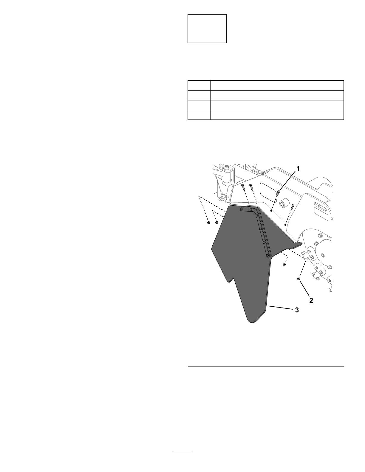
1.Removetheshieldassemblyfromthegrinder
head(Figure12).Retainthefasteners.
g309639
Figure12
1.Bolt—5/16x1-1/4inches
(8)
3.Shieldassembly
2.Locknut—5/16inch(8)
2.Removebothshieldsandclampplatesfromthe
guardmount(Figure13).Retainthefasteners
andshields.
6
g309640
Figure13
1.Bolt—5/16x1-1/4inches
(12)
4.Locknut—5/16inch(12)
2.Clampplate(2)5.Guardmount
3.Shield(2)
3.Installthenewguardmountusing8boltsand8
nutsthatyouremovedinstep1(Figure14).
g309638
Figure14
1.Bolt—5/16x1-1/4inches
(8)
3.Locknut—5/16inch(8)
2.Guardmount
4.Installbothshieldstotheguardmountusing
aclampplateandthe6boltsand6nutsyou
removedfromeachshieldinstep2(Figure15).
Note:Donotusetherearholeintheclamp
platesinthisstep.
g309637
Figure15
1.Bolt—5/16x1-1/4inches
(12)
4.Guardmount
2.Clampplate(2)5.Locknut—5/16inch(12)
3.Shield(2)
5.Usingtheclampplateandguardmountasa
template,drillahole(5/16inchdiameter)into
bothshields(Figure16).
g309636
Figure16
1.Drillahole(5/16inchdiameter)here.
6.Installaboltandnutinbothholes.
7
/