Page is loading ...

FormNo.3425-502RevA
ProCore
®
SR54,SR54-S,SR70,
SR70-S,andSR72Aerator
ModelNo.09931—SerialNo.318000119andUp
ModelNo.09932—SerialNo.318000113andUp
ModelNo.09933—SerialNo.318000113andUp
ModelNo.09934—SerialNo.318000113andUp
ModelNo.09935—SerialNo.318000143andUp
Registeratwww.Toro.com.
OriginalInstructions(EN)
*3425-502*A

ThisproductcomplieswithallrelevantEuropean
directiveswhenalltheappropriatesetupprocedures
havebeencompleted;fordetails,pleaseseethe
separateproductspecicDeclarationofConformity
(DOC)sheet.
WARNING
CALIFORNIA
Proposition65Warning
Useofthisproductmaycauseexposure
tochemicalsknowntotheStateof
Californiatocausecancer,birthdefects,
orotherreproductiveharm.
Introduction
Thismachineisintendedforusebyprofessional,
hiredoperatorsincommercialapplications.This
machineisdesignedprimarilyforworkinglargeareas
onwell-maintainedlawnsinparks,golfcourses,
sportselds,andoncommercialgrounds.Usingthis
productforpurposesotherthanitsintendedusecould
provedangeroustoyouandbystanders.
Readthisinformationcarefullytolearnhowtooperate
andmaintainyourproductproperlyandtoavoid
injuryandproductdamage.Youareresponsiblefor
operatingtheproductproperlyandsafely.
Visitwww.T oro.comforproductsafetyandoperation
trainingmaterials,accessoryinformation,helpnding
adealer,ortoregisteryourproduct.
Wheneveryouneedservice,genuineT oroparts,or
additionalinformationcontactanAuthorizedService
DealerorT oroCustomerServiceandhavethemodel
andserialnumbersofyourproductready.Figure1
identiesthelocationofthemodelandserialnumbers
ontheproduct.Writethenumbersinthespace
provided.
Important:Withyourmobiledevice,youcan
scantheQRcode(ifequipped)ontheserial
numberplatetoaccesswarranty,parts,andother
productinformation.
g235770
Figure1
1.Modelandserialnumberlocation
ModelNo.
SerialNo.
Thismanualidentiespotentialhazardsandhas
safetymessagesidentiedbythesafety-alertsymbol
(Figure2),whichsignalsahazardthatmaycause
seriousinjuryordeathifyoudonotfollowthe
recommendedprecautions.
g000502
Figure2
1.Safety-alertsymbol
Thismanualuses2wordstohighlightinformation.
Importantcallsattentiontospecialmechanical
informationandNoteemphasizesgeneralinformation
worthyofspecialattention.
©2018—TheToro®Company
8111LyndaleAvenueSouth
Bloomington,MN55420
2
Contactusatwww.Toro.com.
PrintedintheUSA
AllRightsReserved

Contents
Safety.......................................................................4
GeneralSafety...................................................4
SafetyandInstructionalDecals..........................4
Setup........................................................................7
1RemovingtheAeratorfromthe
Crating............................................................8
2ConnectingtheLowerLinkArms......................8
3ConnectingtheHydraulicTopLink...................9
4InstallingtheDepthGauge..............................11
5ConnectingtheTractionUnitUpper
Link...............................................................12
6VerifyingtheHydraulicT opLink
Setup............................................................12
7CheckingthePTOAngle................................13
8FittingthePTOShaft......................................13
9InstallingthePTOShield................................15
10ConnectingthePTOShaft...........................15
11AdjustingtheSwayLinks..............................17
12LevelingtheAeratorSide-to-Side.................17
13InstallingtheTines.......................................18
14SettingtheTineDepth..................................18
15InstallingtheRearGuard.............................18
16RemovingtheStorageStands.....................19
17InstallingtheLatchLock...............................20
18ApplyingtheCEDecalandtheProduction
YearDecal....................................................20
ProductOverview...................................................22
Specications..................................................22
Attachments/Accessories.................................22
BeforeOperation.................................................23
BeforeOperationSafety...................................23
OutcrossTractionUnitControls........................23
TractionUnitControls.......................................23
PrinciplesofOperation.....................................23
TractionUnitPTOSpeed..................................23
TrainingPeriod.................................................24
BeforeAerating................................................24
DuringOperation.................................................24
DuringOperationSafety...................................24
SlopeSafety.....................................................25
AeratingProcedures.........................................25
SubsoilCultivation............................................25
HardGround.....................................................26
Longer/LargerTines.........................................26
MultiRowAdapterHeads.................................26
RootZoneLifting..............................................26
AdjustingtheTineAngle(ModelsSR54,
SR54-S,SR70andSR70-S).........................26
AdjustingtheTineAngle(ModelSR72).............27
AdjustingtheTineDepth(ModelsSR54-S
andSR70-S).................................................27
AdjustingtheTineDepth(ModelsSR54,
SR70,andSR72)..........................................27
AdjustingtheHeadReturnSprings...................28
TransportOperation.........................................29
OperatingTips.................................................29
AfterOperation....................................................29
AfterOperationSafety......................................29
CleaningandInspectingtheMachine...............29
Maintenance...........................................................31
RecommendedMaintenanceSchedule(s)...........31
MaintenanceSafety..........................................31
LiftingtheMachine...........................................31
GreasingthePTOShaftandRoller
Bearings........................................................32
GearboxOilSpecication.................................32
CheckingtheGearboxOil.................................32
ChangingtheGearboxOil................................33
Inspecting/AdjustingtheDriveChain................33
AdjustingtheDriveChain.................................33
LubricatingtheDriveChain...............................34
AdjustingthePTOClutch..................................34
FastenerT orqueSpecications........................34
CheckingtheSprings........................................35
AdjustingtheHoleSpacing...............................35
RemovingtheAeratorfromtheTraction
Unit...............................................................35
Troubleshooting................................................36
Storage...................................................................37
StorageSafety..................................................37
StoringtheMachine..........................................37
3

Safety
GeneralSafety
Thisproductiscapableofcausingpersonalinjury.
Alwaysfollowallsafetyinstructionstoavoidserious
personalinjury.
•Readandunderstandthecontentsofboththis
Operator’sManualandtheoperator’smanualof
thetractionunitbeforeusingthismachine.Ensure
thateveryoneusingthisproductknowshowtouse
thismachineandthetractionunitandunderstands
thewarnings.
•Donotputyourhandsorfeetnearmoving
componentsofthemachine.
•Donotoperatethemachinewithoutallguards
andothersafetyprotectivedevicesinplaceand
workingonthemachine.
•Keepthemachineasafedistanceawayfrom
bystanderswhileitismoving.
•Keepchildrenoutoftheoperatingarea.Never
allowchildrentooperatethemachine.
•Stopthemachine,shutofftheengine,engagethe
parkingbrake,removethekey,andwaitforall
movingpartstostopbeforeservicing,fueling,or
uncloggingthemachine.
Improperlyusingormaintainingthismachinecan
resultininjury.Toreducethepotentialforinjury,
complywiththesesafetyinstructionsandalways
payattentiontothesafety-alertsymbol
,which
meansCaution,Warning,orDanger—personalsafety
instruction.Failuretocomplywiththeseinstructions
mayresultinpersonalinjuryordeath.
Youcanndadditionalsafetyinformationwhere
neededthroughoutthismanual.
SafetyandInstructionalDecals
Safetydecalsandinstructionsareeasilyvisibletotheoperatorandarelocatednearanyarea
ofpotentialdanger.Replaceanydecalthatisdamagedormissing.
decal117-7052
117–7052
1.ReadtheOperator’sManual,donotoilthechaindrive.
decal100-3612
100–3612
1.Entanglementhazard—stayawayfrommovingparts,keep
allguardsandshieldsinplace.
decal127-4235
127-4235
1.Entanglementhazard,shaft—stayawayfrommovingparts.
2.ReadtheOperator'sManual;PTOspeedandinput
direction.
3.Usethecliptosecurethelashcablewhennotinuse.Use
thelashcabletosupporttheshaftwhenthemachineis
disconnectedfromthetowvehicle.
decal117-7051
117-7051
1.Crushinghazardofhandorfoot—keepbystandersaway.
4

decal92-1581
92–1581
decal92-1582
92–1582
decal117-7050
117-7050
1.Warning—readtheOperator'sManual.
2.Warning—removetheignitionkeyandreadtheinstructionsbeforeservicingorperformingmaintenance.
3.Warning—donotoperatethismachineunlessyouaretrained.
4.Entanglementhazard,belt—stayawayfrommovingparts,keepallguardsinplace.
5.Crushinghazardofhandorfoot—keepbystandersasafedistanceawayfromthemachine.
6.Crushinghazardofhandandbody—supportmachineonstandwhennotinuse.
7.Fallinghazard—donotcarrypassengers.
decal120-0625
120-0625
1.Pinchpoint,hand—keephandsaway.
5

decal121-6926
121-6926
1.Tinedepth—deep2.Tinedepth—shallow
decal133-8061
133-8061
6

Setup
LooseParts
Usethechartbelowtoverifythatallpartshavebeenshipped.
ProcedureDescription
Qty.
Use
1
Nopartsrequired
–
Removetheaeratorfromthecrating.
Hitchpin2
2
Lynchpin2
Connectthelowerlinkarms(theSR54
andSR54-Saeratorsshipwiththehitch
pinsandlynchpinsinstalled).
Hydraulictoplink1
Hydraulichose—106cm(3-1/2ft)
1
Hydraulichose—76cm(2-1/2ft)
1
Extensionbracket2
Rotationalbracket1
3
Hosequickcouplings2
Connectthehydraulictoplink(Models
SR54,SR70,andSR72).
Depthgauge1
Slideblock
1
Machinescrew(#10x1/2inch)
2
Screw(1/4x2-1/2inch)
2
Tubeclamp1
Weldplate1
4
Depthdecal1
Installthedepthgauge.
Spring-loadedtoplink
1
Linkpin3
5
Lynchpin3
Connecttheupperlink(ModelsSR54-S
andSR70-S).
6
Nopartsrequired
–
Verifythetoplinksetup.
7
Nopartsrequired
–
CheckthePTOangle.
8
PTOshaft
1
FitthePTOshaft.
9
PTOshield
1
InstallthePTOshield.
Pin(suppliedwiththePTOshaft)
1
10
Nut(suppliedwiththePTOshaft)
1
ConnectthePTOshaft.
11
Nopartsrequired
–
Adjusttheswaylinks.
12
Level(notsupplied)
1Leveltheaeratorside-to-side.
13
Tines(asrequired)
–
Installthetines.
14
Nopartsrequired
–
Setthetinedepth.
Rearguard1
Screw(3/8x3-1/4inch)
4
Flatwasher(0.438x1inch)
12
Locknut4
15
Endcap2
Installtherearguard.
7

ProcedureDescription
Qty.
Use
16
Nopartsrequired
–
Removethestoragestands.
Lockplate2
Tapbolt2
17
Retainingring2
Installthelatchlock.
CEdecal
1
18
Productionyeardecal1
ApplytheCEdecalandtheproduction
yeardecal.
MediaandAdditionalParts
Description
Qty.
Use
Operator'sManual
1
Readbeforeoperatingtheaerator
Springwires(SR54andSR54-S)
6Replacementspringwires
Springwires(SR70andSR70-S)
8Replacementspringwires
Springwires(SR72)
4Replacementspringwires
Springwires(SR72)
2Replacementspringwires
PTOOperatorsManual
1
Readbeforeoperatingtheaerator
1
RemovingtheAeratorfrom
theCrating
NoPartsRequired
Procedure
1.Removetheaeratorfromthecrating.
2.Removetheboltssecuringtheaeratorstorage
standstotheshippingpalletandremovethe
aeratorfromthepallet.
3.Removethestoragestandsfromtheaerator.
Retainthemforstorageuse.
Note:TheSR54-SandtheSR70-Sdonot
haveshippingstands.
4.Placetheaeratoronaat,levelsurfacewiththe
frontrolleronthegroundandablockofwood
positionedundertheheads.
2
ConnectingtheLowerLink
Arms
Partsneededforthisprocedure:
2Hitchpin
2Lynchpin
Procedure
1.EnsurethatthePTOisdisengaged.
2.Backthetractionunitsquarelytotheaerator
untilthelowerlinkarmsalignwiththemounting
brackets.
Note:Theaeratorgearboxshaftshouldalign
withthetractionunitPTOshaft(centeredonthe
tractionunit).Ifshaftsmisalign,adjustthelower
linkarms,fromsidetosideuntiltheshaftsalign.
3.Engagetheparkingbrake,shutofftheengine,
andremovethekey.Waitfortheengineand
allmovingpartstostopbeforeleavingthe
operator'sseat.
Note:Formaximumgroundclearance,secure
thehitchpinsintheaeratoratthelowermounting
bracketholes,whensoequipped.T odetermine
8

whentousetheuppermountingholes,referto
10ConnectingthePTOShaft(page15).
SR54andSR54-SAeratorsonly
Note:Thefactoryinstallsthehitchpinsand
lynchpinsontotheSR54andSR54-Saerators
beforeshipping.
4.Securethelowerlinkarmstotheaerator
mountingpinswithlynchpins(Figure3).
g016127
Figure3
1.Aeratormountingpin3.Lynchpin
2.Lowerlink
SR70,SR70-S,andSR72Aeratorsonly
5.Securethelowerlinkarmstotheaerator
mountingbracketswithhitchpinsandlynchpins
(Figure4).
g016183
Figure4
1.Hitchpin3.Lowerlink
2.Aeratormountingbracket4.Lynchpin
3
ConnectingtheHydraulic
TopLink
ModelsSR54,SR70,andSR72
Partsneededforthisprocedure:
1Hydraulictoplink
1
Hydraulichose—106cm(3-1/2ft)
1
Hydraulichose—76cm(2-1/2ft)
2Extensionbracket
1Rotationalbracket
2Hosequickcouplings
Procedure
Note:Makesurethatthesuppliedcouplingsare
correctforthetractionunit.Ifnot,contactthetraction
unitmanufacturertoobtainthecorrectcouplings.
Yourtractionunitmusthaveadoubleacting
spoolvalvewithanoperatorcontrolleverand2
quick-releasecouplings12.7mm(1/2inch)atthe
rearofthetractionunit.Thefactoryprovides2quick
couplingstotontothehydraulictoplinkhoses
(1/2-14NPTFhoseendthreadsize).
Usetheprocedurethatfollowstoinstallthehoses
anddeterminetheneedfortheextensionorrotation
blocks.Thisinformationalsohelpsyoutodetermine
thedepthrangeoftheaerator.
1.Securetheconnectinglinkendofthehydraulic
toplinktothetractionunitwiththepinssupplied
withthetractionunit(Figure5).
Positionthehydraulictoplinksothattherod
endistowardtheaeratorandthecylinderports
aligntowardtheauxiliarypowerhydraulicsof
thetractionunit.
Note:Ifyoumustpositionthehydrauliccylinder
withtheportsfacingupward,usetherotational
blockinsteadofthestandardmountingblockto
repositionthecylinder(Figure5).Youmayuse
a90°hydraulicttinginsteadoftherotational
block(90°ttingsarenotincluded).
Installtherotationalblockasfollows:
A.Removethecotterpinandpinsecuring
thestandardconnectinglinktothecylinder
(Figure5).Removetheconnectinglink
fromthecylinder.
9

B.Installtherotationalblocktothecylinder
withthepinspreviouslyremoved(Figure5).
g010840
Figure5
1.Aeratorhitchpin7.Tractionunitlinkpin
2.Hydraulictoplink
8.Clevisandlynchpin
3.Rotationalblock9.Hydraulichose—76cm
(2-1/2ft)
4.Connectinglink
10.Hydraulichose—106cm
(3-1/2ft)
5.3inchextensionblock11.Hosequickcouplings
6.5inchextensionblock12.Tractionunithydraulic
ports
2.Connectthelonghydraulichose—106cm(3-1/2
ft)tothehydraulictoplinkportthatisclosestto
theaeratorFigure5.Applypipe-threadsealing
tapeorcompoundtothehosethreadstoprevent
anyleaks.
3.Connecttheshorthydraulichose—76cm(2-1/2
ft)tothehydraulictoplinkportthatisclosestto
thetractionunit(Figure5).Applypipe-thread
sealingtapeorcompoundtothehosethreadsto
preventanyleaks.
4.Installquickcouplingstothehydraulichoses
(1/2-14NPTFhoseendthreadsize).Apply
pipe-threadsealingtapeorcompoundtothe
hosethreadstopreventanyleaks.
5.Connectthe2hydraulichosequickcouplingsto
theportsprovidedonthetractionunit.
6.Starttheengineofthetractionunitandoperate
thespoolvalvetochecktheextendandretract
motionofthehydraulictoplink.
Note:Iftheliftingandloweringtheaeratordoes
notagreewiththetractionunitcontroloperation,
reversethehoseconnectionsatthetractionunit.
7.Securetherodendofhydraulictoplinktothe
mostforwardholepossibleintheaeratorbracket
withlinkpinandlynchpin(Figure6orFigure7).
Important:Whensecuringtherodendof
thehydrauliclink,usethemostforward
mountingholesinthemountingbracketso
thatthereisenoughclearanceforthebarrel
ofthecylinderwhenretracted.
g016184
Figure6
SR54andSR70mountingshown
1.Rodendofcylinder
3.Linkpin
2.Lynchpin
4.Aeratorbracket(forward
holes)
g016185
Figure7
SR72mountingshown
1.Lynchpin3.Linkpin
2.Aeratorbracket
4.Rodendofcylinder
Ifthehydrauliccylinderdoesnotreachthe
aeratormountingbracket,useanextension
blockinsteadofthestandardmountingblockto
10

connectthecylindertothetractionunit(Figure
5).
Note:Ifyouinstalltheextensionblockand
needtoretractthecylindertoinstallit,the
aeratortineheadswillgetclosertotheground.
Installtheextensionblocksasfollows:
A.Removethecotterpinandpinsecuring
thestandardconnectinglinktothecylinder
(Figure5).Removetheconnectinglink
fromthecylinder.
B.Installtherequiredlengthextensionblock
tothecylinderwiththepinspreviously
removed(Figure5).
4
InstallingtheDepthGauge
ModelsSR54,SR70,andSR72
Partsneededforthisprocedure:
1Depthgauge
1
Slideblock
2
Machinescrew(#10x1/2inch)
2
Screw(1/4x2-1/2inch)
1Tubeclamp
1Weldplate
1Depthdecal
Procedure
1.Mountthedepthgaugetotheatsideofthe
slideblockwith2machinescrews(#10x1/2
inch),positioningthecomponentsasshownin
Figure8.
g024283
Figure8
1.Screw
5.Depthdecal
2.Depthgauge
6.Cylinder
3.Machinescrew(2)
7.Weldplate
4.Slideblock
8.Tubeclamp
2.Usingthetubeclamp,weldplateand2screws
(1/4x2-1/2inches),looselymountthedepth
gaugetotherodendofthetoplinkcylinder
(Figure8).Makesurethattheclampsareloose
enoughtoallowthemtorotatetothedesired
position.
3.Makesurethatthetopofthecylinderisclean
enoughtoexcepttheinstallationofadecal.
4.Afxthedepthdecaltothetopofthecylinder
atalocationthatisvisiblefromtheoperating
positionanddoesnotinterferewithhydraulic
hosesorotherobstructions(Figure8).Alignthe
endofthedecalwiththeletter“J”towardthe
aerator.
5.Checktomakesurethecylinderrodcanextend
andretractfullywithoutinterferingwithother
tractionunitoraeratorcomponents.Whenthe
depthgaugeinpositionedcorrectly,tighten
mountingscrews.
6.Runtheaeratoronatestplottodeterminethe
desiredsettingandnotethecorresponding
positiononthedepthindicator.
Ifneeded,youcanadjustthecylinderwhile
operationtheaeratortoadeepersetting(toward
“J”)orshallowersetting(toward“A”).
11

Note:Thelettersonthedecalcorrespondtoa
relativedepth.
5
ConnectingtheTraction
UnitUpperLink
ModelsSR54-SandSR70-S
Partsneededforthisprocedure:
1
Spring-loadedtoplink
3Linkpin
3Lynchpin
Procedure
1.Mountthespring-loadedtoplinktotheaerator
bracketwith2linkpinsandlynchpins(Figure9)
2.Loosenthelocknutonthetractionunitupper
link.Adjusttheupperlinklengthuntilitaligns
withtheclevisonthespring-loadedtoplinkof
theaerator(Figure9).
g010966
Figure9
1.Spring-loadedtoplink
4.Lynchpin
2.Upperlink5.Locknut
3.Linkpin
3.Connectthetractionunitupperlinktotheclevis
onthespring-loadedtoplinkandsecurewitha
linkpinandlynchpin(Figure9).
4.Greasethethreadedsteelupperlinktubes.
5.Measurethelengthofthespringinthetoplink.
6.Rotatetheupperlinkuntilthespringcompresses
approximately13mm(1/2inch)(Figure9).
7.Tightenthelocknuttosecuretheupperlinkinto
position.
6
VerifyingtheHydraulicTop
LinkSetup
NoPartsRequired
Procedure
Extendingthehydrauliccylinderincreasesthetine
depth.
1.Fullyextendthehydrauliccylindertodetermine
thelocationofthetineheadsandtoverifyifthey
contacttheground.
Note:Onundulatingturf,theoperatorcan
adjustthecylindertomaintaintinedepth
(crestingahill)butitwillbenecessarytohave
thetineheadssetabout5cm(2inches)below
ground.
•Ifthetineheadscontacttheground,turf
damagemayoccur.
Ifthetineheadscontacttheground,adjust
thelocationofthecylinderendstomovethe
topoftheaeratorclosertothetractionunit.
•Ifthetineheadsdonotcontacttheground,
youcaninstallextensionbrackets(included
withaerator)ontothetoplinktomovethe
tineheadsclosertotheground.
2.Retractthehydrauliccylindertoliftthetine
heads.
Important:WhenconnectingthePTO,
donottolifttheaeratorhigherthanis
necessary.Liftingthemachinetoohigh
willcausethePTOshaftknucklestobreak
(Figure10).ShutoffthePTOwhenyouraise
theaerator.YoucanoperatethePTOupto
anangleof25°,butdonotexceeda35°angle
whentheaeratorisatitshighestposition;
otherwise,severeshaftdamagemayoccur.
12

g010803
Figure10
1.Damagewilloccurhere.
7
CheckingthePTOAngle
NoPartsRequired
Procedure
Important:BeforecheckingthePTOangle,
removethetines.
1.Withtheaeratorpositionedonthegroundand
loweredtothedeepestlocation,useanangle
indictortomeasuretheanglebetweenthePTO
andtheaerator.
2.Lifttheaeratorandfullyretractthehydraulictop
linkcylinder.
3.Usinganangleindictor,checktheangle
betweenthePTOandtheaerator.
4.Ifyourmeasurementisgreaterthan35°,perform
1ofthefollowingtoadjustthetractionunitso
thatyoucannotraisetheaeratorpast35°.
•Usetheliftstopofthetractionunit(if
equipped).
•Movethelowerlinkstoahighermounting
hole(ifequipped).
8
FittingthePTOShaft
Partsneededforthisprocedure:
1
PTOshaft
Procedure
1.Parkthetractionunitandaeratoronalevel
surface.
2.Raisetheaeratorcompletelyandfullyretractthe
hydraulictoplinkcylinderorupperlink(Figure
11).
g010798
Figure11
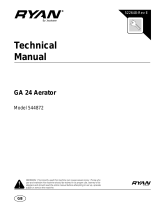
3.Measurethedistancefromthelockinggroove
attheendofthetractionunitPTOshafttothe
lockinggrooveattheaeratorgearboxshaft
(Figure12).
Recordthismeasurementhere:
EXAMPLE:67CM(26-1/2
INCHES)
g237884
Figure12
1.Measurehere2.Lockinggroove
4.Lowertheaeratortothegroundandfullyextend
thehydraulictoplinkcylinderorupperlink
(Figure13).
13

g010807
Figure13
5.Measurethedistancefromthelockinggroove
attheendofthetractionunitPTOshafttothe
lockinggrooveattheaeratorgearboxshaft
(Figure14).
Recordthismeasurementhere:
EXAMPLE:70CM(27-1/2
INCHES)
g237883
Figure14
1.Measurehere2.Lockinggroove
6.Measurethedistancefromthecenteroflocking
pinballattheendofthePTOshafttothecenter
ofthelockingpinontheotherend(Figure15).
Recordthismeasurementhere:
EXAMPLE:81CM(32INCHES)
g237882
Figure15
1.Measurehere
7.Usingthesmallerofthe2measurementsin
Figure14andFigure12,subtractthatdistance
fromthedistanceinFigure15.Example:81cm
(32inches)minus67cm(26-1/2inches)equals
14cm(5-1/2inches).
8.Theexamplemeasurementsshowthattheshaft
is14cm(5-1/2inches)toolong.Addanextra
1.2cm(1/2inch)toensurethatthePTOshaft
doesnotbottomoutwhenyoulifttheaerator
toitshighestposition.
EXAMPLE:14CM(5-1/2INCHES)PLUS1.2CM(1/2
INCH)EQUALS15CM(6INCHES)
9.FullyslidetogetherthePTOshafttubes.Verify
thattheinsidetubedoesnotprotrudeintothe
crossandbearingsectionoftheoutertube
(Figure16).Ifthishappens,youneedtocutoff
moreoftheinsidetube—proceedtonextstep.
10.Measurethedistancetheinsidetubeprotrudes
intothecrossandbearingsectionoftheouter
tube(Figure16).Addthisdistancetothe
dimensionattainedinstep8.
g237881
Figure16
1.Cutoff
2.Insidetube
11.Separatethe2halvesofthePTOshaft(Figure
17).
12.Measurethedistancefromtheendofeachtube
toitssafetyshield(Figure17).
Recordthemeasurementshere
and.
g237887
Figure17
13.Usingthedimensionsdeterminedinstep8,
locate,mark,andcutofftheshieldandtube
fromeachPTOhalf(Figure18andFigure19).
14

Note:Cutoffmoreoftheinsidetubeifit
protrudesintothecrossandbearingsectionof
theoutertube.
g237888
Figure18
g237889
Figure19
14.Usingthedimensionsdeterminedinstep11,
locate,markandcutoffjustthesafetyshieldsto
exposethetubes(Figure20andFigure21).
g237890
Figure20
g237891
Figure21
15.Carefullyremoveanyburrsfromtheendsofthe
tubeswithaleandremoveallthelingsfrom
thetubes.
16.Greasetheinsidetube.
Note:Thetelescopingtubesmustalways
overlapby1/2oftheirlengthduringnormal
operationandatleast1/3oftheirlengthduring
allworkingconditions.Duringtransport,when
thedrivelineisnotrotating,thetelescoping
tubesmusthaveasuitableoverlaptomaintain
alignmentofthetubesandallowthemtoslide
freely.
9
InstallingthePTOShield
Partsneededforthisprocedure:
1
PTOshield
Procedure
1.Removethe4bolts,lockwashers,andat
washerssecuredtotherearoftheaerator
gearbox(Figure22).
g010849
Figure22
1.PTOshield
4.Bolt
2.Flatwasher5.Accesspanel
3.Lockwasher
2.MountthePTOshieldtotheaeratorgearbox
withthefastenerspreviouslyremoved(Figure
22).
Aligntheaccesspanel(Figure22)ofthePTO
shieldtothetoporthesidedependingonthe
aeratorframeconguration.
15

10
ConnectingthePTOShaft
Partsneededforthisprocedure:
1
Pin(suppliedwiththePTOshaft)
1
Nut(suppliedwiththePTOshaft)
Procedure
Note:Youcanopentheaccesspanel(Figure22)to
easetheremovalandinstallationofthePTOshaft
mountingfasteners.
1.RemovethepinandnutfromthePTOshaft
(Figure23).
2.ConnecttheclutchendofthePTOshafttothe
aeratorgearboxinputshaftwithpinandnut
previouslyremoved(Figure23).
Note:Youcaninsertpinonlyoneway.
g010850
Figure23
1.Gearboxinputshaft
3.Pin
2.PTOshaftcoupler
4.Nut
Note:CloseandlatchthePTOshieldaccess
panelifopened.
Note:Ensurethatthepinfullyinsertsintothe
yokeofthePTO.
3.ConnectthePTOshafttothetractionunitPTO
shaft(Figure24).
g007328
Figure24
1.Tractionunitoutputshaft3.PTOshaft
2.PTOshaftcoupler
4.SlidethePTOshaftforwardasfarasthetraction
unitallows.
5.PullbackthelockingcollartosecurethePTO
shaftinplace.SlidethePTOshaftbackand
forthtoensurethatitisproperlylocked.
6.ConnecttheshieldsafetychainstothePTO
shieldandthetractionunitbracket(Figure
25).Ensurethatthechainsremainslackwhen
raisingandloweringtheaerator.
g010852
Figure25
1.Safetychains
Note:T oavoidexcesslift,connecttheliftarms
ofthetractionunitintothetopholesofthelift
bracket,ifequipped(Figure26).Themaximum
angleonthePTOshaftis35°.
16

g010804
Figure26
1.Topholes
Important:Donotlifttheaeratorhigher
thannecessarywhenconnectingthePTO.
Liftingthemachinetoohighwillcausethe
PTOshaftknucklestobreak(Figure27).
ShutoffthePTOwhenliftingtheaerator.You
canoperatethePTOuptoa25°angle,but
neverexceeda35°anglewhentheaeratoris
atitshighestposition.
7.VerifythatthePTOshielddoesnotinterferewith
theclutch.
g010803
Figure27
1.Breakagewilloccurhere.
11
AdjustingtheSwayLinks
NoPartsRequired
Procedure
Wheninstalledcorrectly,theaeratoriscenteredwith
thePTO-shaftcenterlineofthetractionunit.Adjust
theswaylinkstocentertheaerator.
Important:ThePTOshaftshouldbeasstraight
aspossibletothetractionunitPTOshaft.
1.Adjusttheswaylinksonthelowerliftarmsto
minimizeside-to-sideswaytoamaximumof25
mm(1inch)ateachside(Figure28).
g007333
Figure28
1.Swaylink
2.Adjustthelowerlinksinboarduntiltheycontact
theaeratormountingplates;refertothetraction
unitoperator'smanualforadditionalinstallation
andadjustmentprocedures.
Note:Thisreducesthestressonthepins.
3.Ifthetractionunithasswaychainsinsteadof
swaylinks,installwashersbetweenthelower
linkarmandlynchpintoreducetheoverhung
loadontheliftpins.
12
LevelingtheAerator
Side-to-Side
Partsneededforthisprocedure:
1
Level(notsupplied)
Procedure
1.Parkthetractionunitandaeratoronarm,level
surface.
2.Placealevelontopoftheaeratorframeto
checkforlevelside-to-side(Figure29).
17

g010854
Figure29
1.Level
3.Turntheadjustablelinkbody(ifprovided)to
raiseorlowerthelinkarmuntiltheaeratorlevels
side-to-side.
Note:Refertothetractionunitoperator's
manualforadditionaladjustmentprocedures.
13
InstallingtheTines
Partsneededforthisprocedure:
–
Tines(asrequired)
Procedure
Youcanchoosefromawideselectionoftinesforthe
aerator.Choosethetinetype,size,andspacings
requiredforthejob.RefertothePartsCatalogforthe
listofaccessories.
1.Ensurethatthestandsorsupportblocksfully
supporttheaerator.
2.Turnoffthetractionunitengineandremovethe
key.
3.Loosentheclampingboltsandremovethe
previouslyusedtines(Figure30).
g016131
Figure30
1.Tine
2.Clampingbolt
4.Slidethenewtinesintotheholessizedtotthe
tinesselected.Neverusesmalldiametertines
inthelargediameterholes;thetinesshouldt
closelyinthehole.Besuretoslidethetineup
intotheheaduntilitbottomsout.
Note:Positionhollowcoringtineswiththe
ejectionslottotherear.Positionsolidtineswith
thetinetipanglefacingthemachine(Figure30).
5.Tightentheclampingboltsrmlytosecurethe
tines.Donotuseimpacttools.
6.Setthetineangleforthenewtines;refer
toAdjustingtheTineAngle(ModelsSR54,
SR54-S,SR70andSR70-S)(page26)or
AdjustingtheTineAngle(ModelSR72)(page
27).
7.Beforeaeratingformalturfforthersttime
afterinstallingtines,testtheaeratoronaless
importantareasothatyoucantryalternative
tractionunitgearsandnetunetheadjustment
toachievetheholespacingandturfappearance
desired.
14
SettingtheTineDepth
ModelsSR54-SandSR70-S
NoPartsRequired
Procedure
Setthetinedepth;refertoAdjustingtheTineDepth
(ModelsSR54-SandSR70-S)(page27).
18

15
InstallingtheRearGuard
Partsneededforthisprocedure:
1Rearguard
4
Screw(3/8x3-1/4inch)
12
Flatwasher(0.438x1inch)
4Locknut
2Endcap
Procedure
1.Inserttheendcapsintotheendsoftherear
guardtubes(Figure31).
g016186
Figure31
1.Rearguard3.Uppermountinghole
2.Endcap4.Lowermountinghole
2.Aligntheholesintherearguardmountingtubes
withtheholesintheaeratorsideplates(Figure
31).
Note:OnSR54-SandSR70-Smodels,mount
theendsofthetubestothelowersideplate
mountingholesiftheaeratortinedepthissetin
PositionA(Figure32).Usetheuppermounting
holesfordepthsettingPositionsBorC.
g016181
Figure32
3.Securetheguardmountingtubestotheside
plateswith4screws,atwashers,andnuts
(Figure31).
Note:Usetheremainingwashers,asrequired,
tollanygapbetweenthetubesandtheaerator
sideplates.
16
RemovingtheStorage
Stands
NoPartsRequired
PreparingModelsSR54andSR70
1.Raisetheaeratorroller(s)7.5to15cm(3to6
inches)offtheground.Placesupportblocks
undertheroller(s).
2.Removethebolts,lockwashers,andnuts
securingthestoragestandstoeachendofthe
aerator(Figure33).
19

g010857
Figure33
1.Bolts3.Nut
2.Lockwasher
4.Storagestand
3.Removethestoragestands.
4.Usethestoragestandswheneveryouremove
theaeratorfromthetractionunit.
PreparingModelSR72
1.Raisetheaeratorroller(s)7.5to15cm(3to6
inches)offtheground.Placesupportblocks
undertheroller(s).
2.Removethebolts,lockwashers,andnuts
securingthestoragestandstoeachendofthe
aerator(Figure34).
g010967
Figure34
1.Bolts3.Nut
2.Lockwasher
4.Storagestand
3.Removethestoragestands.
4.Usethestoragestandswheneveryouremove
theaeratorfromthetractionunit.
Note:Wheninstallingthestoragestands,
ensurethatthestandsmounttotheinsideofthe
rollerplatessothatthelowerframetuberests
onthetopofthestands.
Note:ModelsSR54-SandSR70-Sdonothave
storagestands.
17
InstallingtheLatchLock
CEOnly
Partsneededforthisprocedure:
2Lockplate
2Tapbolt
2Retainingring
Procedure
1.Positionthelatchplateoverthehoodlatchwhile
aligningthemountingholewiththeholeinthe
sideplate(Figure35).
g016161
Figure35
1.Retainingring3.Latchplate
2.Mountinghole4.Tapbolt
2.Securethelatchplatetothesideplatewithatap
boltandaretainingring(Figure35).
3.Repeattheprocedureontheotherhoodlatch.
20
/