RGB 203 Rxi • Setup Guide
These instructions provide a quick setup guide for the
Extron® RGB 203 Rxi interface. Installation and service must be
performed by authorized personnel only.
There are two RGB 203 Rxi models: one with EDID Minder
®
and one with
ADSP
™
. Unless otherwise stated, all instructions refer to both models.
Internal Conguration
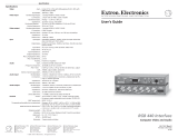
Step 1: Congure sync settings — Turn off all equipment and disconnect the
power sources. Remove the cover from the interface and locate jumper blocks J6,
J7, J20, and J11 (as shown at right).
CAUTION: Only authorized service personnel should perform changes to
internal jumpers. Take steps to prevent electrostatic discharge.
Set output sync to follow input sync: remove the jumper from J20.
Set vertical sync: for negative V sync, remove jumper from J7; for positive V sync, install jumper on J7.
Set horizontal sync: for negative H sync, remove jumper from J6; for positive H sync, install jumper on J6.
Clamp sync timing to back porch: place jumper between pins 1 and 2 on J11.
Clamp sync timing to sync tip: place jumper between pins 2 and 3 on J11.
Mounting
Step 2: Mount interface — Choose a suitable place to mount the interface (see the RGB 203 Rxi User Guide for details).
Rear Panel Connections
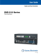
Both RGB 203 Rxi interfaces have identical rear panel connections. Connect, but do not power on, input and output devices.
Step 3: Connect Video Inputs — Connect an RGBHV, RGBS, RGsB, or RsGsBs video input
to each 15-pin HD connector (
a
), as desired.
Step 4: Connect Audio Inputs — Connect an unbalanced stereo audio source to each
3.5 mm mini tip-ring-sleeve (TRS) stereo audio connector (
b
) for unbalanced audio input, as
desired. Wire the connector as shown in the figure at right.
NOTE: The interface accepts audio on inputs 1 and 2 only. When you select input 3, the
audio output is muted.
Step 5: Connect Local Monitor — If required, connect a monitor to this 15-pin HD connector (
c
).
Step 6: Connect Video Output — Connect the RGBHV, RGBS, or RGsB video display to the output
connectors (
d
) as shown in the figure at right.
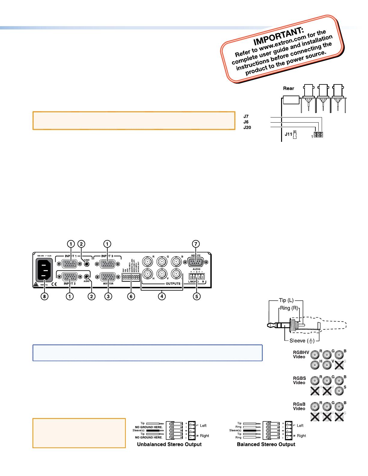
Step 7: Connect Audio Output — Connect an audio device to this 3.5 mm, 5-pole captive screw
connector (
e
) for balanced or unbalanced audio output. For correct wiring, see the diagram below.
CAUTION:
For unbalanced audio, connect
the sleeves to the center
contact ground.
DO NOT connect the sleeves
to the negative (-) contacts.
3
2
1
V Sync
H Sync
Enable
Sync