Page is loading ...

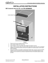
CONTINUOUS FLOW ICE MAKER
500, 700, 2000 - Series
Installation Manual
Release Date: July 1, 2008
Publication Number: 630460174INS
Revision Date: December 12, 2019
Revision: P
Visit the Cornelius web site at www.cornelius.com for all your Literature needs.

The products, technical information, and instructions contained in this manual are subject to change without notice.
These instructions are not intended to cover all details or variations of the equipment, nor to provide for every possi
-
ble contingency in the installation, operation or maintenance of this equipment. This manual assumes that the per-
son(s) working on the equipment have been trained and are skilled in working with electrical, plumbing, pneumatic,
and mechanical equipment. It is assumed that appropriate safety precautions are taken and that all local safety and
construction requirements are being met, in addition to the information contained in this manual.
This Product is warranted only as provided in Cornelius’ Commercial Warranty applicable to this Product and is sub-
ject to all of the restrictions and limitations contained in the Commercial Warranty.
Cornelius will not be responsible for any repair, replacement or other service required by or loss or damage resulting
from any of the following occurrences, including but not limited to, (1) other than normal and proper use and normal
service conditions with respect to the Product, (2) improper voltage, (3) inadequate wiring, (4) abuse, (5) accident,
(6) alteration, (7) misuse, (8) neglect, (9) unauthorized repair or the failure to utilize suitably qualified and trained per
-
sons to perform service and/or repair of the Product, (10) improper cleaning, (11) failure to follow installation, oper-
ating, cleaning or maintenance instructions, (12) use of “non-authorized” parts (i.e., parts that are not 100%
compatible with the Product) which use voids the entire warranty, (13) Product parts in contact with water or the
product dispensed which are adversely impacted by changes in liquid scale or chemical composition.
Contact Information:
To inquire about current revisions of this and other documentation or for assistance with any Cornelius product con-
tact:
www.cornelius.com
800-238-3600
Trademarks and Copyrights:
This document contains proprietary information and it may not be reproduced in any way without permission from
Cornelius.
This document contains the original instructions for the unit described.
CORNELIUS INC
101 Regency Drive
Glendale Heights, IL
Tel: + 1 800-238-3600
Printed in U.S.A.

TABLE OF CONTENTS
SAFETY INSTRUCTION . . . . . . . . . . . . . . . . . . . . . . . . . . . . . . . . . . . . . . . . . . . . . . . . .1
Read and Follow ALL Safety Instructions . . . . . . . . . . . . . . . . . . . . . . . . . . . . . . . . . .1
Safety Overview . . . . . . . . . . . . . . . . . . . . . . . . . . . . . . . . . . . . . . . . . . . . . . . . . .1
Recognition . . . . . . . . . . . . . . . . . . . . . . . . . . . . . . . . . . . . . . . . . . . . . . . . . . . . . .1
Different Types of Alerts . . . . . . . . . . . . . . . . . . . . . . . . . . . . . . . . . . . . . . . . . . . . . . .1
Safety Tips . . . . . . . . . . . . . . . . . . . . . . . . . . . . . . . . . . . . . . . . . . . . . . . . . . . . . . . . .1
Qualified Service Personnel . . . . . . . . . . . . . . . . . . . . . . . . . . . . . . . . . . . . . . . . . . . .1
Safety Precautions . . . . . . . . . . . . . . . . . . . . . . . . . . . . . . . . . . . . . . . . . . . . . . . . . . .2
Shipping And Storage . . . . . . . . . . . . . . . . . . . . . . . . . . . . . . . . . . . . . . . . . . . . . . . . .2
Power Cord . . . . . . . . . . . . . . . . . . . . . . . . . . . . . . . . . . . . . . . . . . . . . . . . . . . . . . . . .2
Sound Level . . . . . . . . . . . . . . . . . . . . . . . . . . . . . . . . . . . . . . . . . . . . . . . . . . . . . . . .2
Unit Location . . . . . . . . . . . . . . . . . . . . . . . . . . . . . . . . . . . . . . . . . . . . . . . . . . . . . . . .2
GENERAL INFORMATION . . . . . . . . . . . . . . . . . . . . . . . . . . . . . . . . . . . . . . . . . . . . . . .3
General Description . . . . . . . . . . . . . . . . . . . . . . . . . . . . . . . . . . . . . . . . . . . . . . . . . .3
Specification Chart . . . . . . . . . . . . . . . . . . . . . . . . . . . . . . . . . . . . . . . . . . . . . . . . . . .3
Temperature Chart . . . . . . . . . . . . . . . . . . . . . . . . . . . . . . . . . . . . . . . . . . . . . . . . . . .3
Dimension Drawing . . . . . . . . . . . . . . . . . . . . . . . . . . . . . . . . . . . . . . . . . . . . . . . . . . . .4
WCC500 & WCC700 Series . . . . . . . . . . . . . . . . . . . . . . . . . . . . . . . . . . . . . . . . . . . .4
WCC 700R . . . . . . . . . . . . . . . . . . . . . . . . . . . . . . . . . . . . . . . . . . . . . . . . . . . . . . . . .4
WCC700R Chunklet Carbon . . . . . . . . . . . . . . . . . . . . . . . . . . . . . . . . . . . . . . . . . . . .5
WCC 700W Chunklet Carbon . . . . . . . . . . . . . . . . . . . . . . . . . . . . . . . . . . . . . . . . . . .5
WCC 700A Chunklet Carbon . . . . . . . . . . . . . . . . . . . . . . . . . . . . . . . . . . . . . . . . . . .6
WCC 700R Chunklet Carbon
(FOR SHORTER UNIT WITH S/N’S STARTING WITH 62Q1930) . . . . . . . . . . . . . . 6
WCC 700A Chunklet Carbon
(FOR SHORTER UNIT WITH S/N’S STARTING WITH 62R1914) . . . . . . . . . . . . . . .7
WCC 700W Chunklet Carbon
(FOR SHORTER UNIT WITH S/N’S STARTING WITH 62R1924) . . . . . . . . . . . . . . .7
WCC 2001R . . . . . . . . . . . . . . . . . . . . . . . . . . . . . . . . . . . . . . . . . . . . . . . . . . . . . . . .8
INSTALLATION INSTRUCTIONS . . . . . . . . . . . . . . . . . . . . . . . . . . . . . . . . . . . . . . . . . .9
Remove Ice maker from Carton . . . . . . . . . . . . . . . . . . . . . . . . . . . . . . . . . . . . . . . . .9
Cabinet Removal Alternate 9 . . . . . . . . . . . . . . . . . . . . . . . . . . . . . . . . . . . . . . . . . . . . .
Preparation of Installation Site . . . . . . . . . . . . . . . . . . . . . . . . . . . . . . . . . . . . . . . . . .9
Water Inlet Hook-up . . . . . . . . . . . . . . . . . . . . . . . . . . . . . . . . . . . . . . . . . . . . . . . . .10
Drain Connection . . . . . . . . . . . . . . . . . . . . . . . . . . . . . . . . . . . . . . . . . . . . . . . . . . .10
Electrical Supply . . . . . . . . . . . . . . . . . . . . . . . . . . . . . . . . . . . . . . . . . . . . . . . . . . . .11
Auger Engagement . . . . . . . . . . . . . . . . . . . . . . . . . . . . . . . . . . . . . . . . . . . . . . . . . .13
Initial Start Up, Checks and Adjustment Instructions . . . . . . . . . . . . . . . . . . . . . . . .15
For WCC2001QT-R Only: . . . . . . . . . . . . . . . . . . . . . . . . . . . . . . . . . . . . . . . . . .15
MOUNTING CHUNKLET ICE MAKER ON A CORNELIUS DISPENSER . . . . . . . . . .16
Description of Potential Issue . . . . . . . . . . . . . . . . . . . . . . . . . . . . . . . . . . . . . . . . . .16
Corrective Action . . . . . . . . . . . . . . . . . . . . . . . . . . . . . . . . . . . . . . . . . . . . . . . . .16
Additional Information . . . . . . . . . . . . . . . . . . . . . . . . . . . . . . . . . . . . . . . . . . . . .16
Compressed Flaked Ice Adjustments . . . . . . . . . . . . . . . . . . . . . . . . . . . . . . . . .16
ED150/175 . . . . . . . . . . . . . . . . . . . . . . . . . . . . . . . . . . . . . . . . . . . . . . . . . .17
ED/DF200 . . . . . . . . . . . . . . . . . . . . . . . . . . . . . . . . . . . . . . . . . . . . . . . . . . .17

ED/DF250 . . . . . . . . . . . . . . . . . . . . . . . . . . . . . . . . . . . . . . . . . . . . . . . . . . .17
ED300 . . . . . . . . . . . . . . . . . . . . . . . . . . . . . . . . . . . . . . . . . . . . . . . . . . . . . .18
Flavor Fusion / Flavor Overload / IDC . . . . . . . . . . . . . . . . . . . . . . . . . . . . . .18
Off Cycle Ice Agitation . . . . . . . . . . . . . . . . . . . . . . . . . . . . . . . . . . . . . . . . . . . . .18
Gear motor . . . . . . . . . . . . . . . . . . . . . . . . . . . . . . . . . . . . . . . . . . . . . . . . . . . . . . . .20
Bin Control . . . . . . . . . . . . . . . . . . . . . . . . . . . . . . . . . . . . . . . . . . . . . . . . . . . . . . . .20
Install Bin control sensor . . . . . . . . . . . . . . . . . . . . . . . . . . . . . . . . . . . . . . . . . . .21
CORNELIUS ICE/BEVERAGE COMBO SOFT ICE DISPENSING TIPS . . . . . . . . . . .22

Continuous Flow Icemaker Installation Manual
© 2004-2019, Cornelius Inc. - 1 - Publication Number: 630460174INS
SAFETY INSTRUCTION
READ AND FOLLOW ALL SAFETY INSTRUCTIONS
Safety Overview
• Read and follow ALL SAFETY INSTRUCTIONS in this manual and any warning/caution labels on the unit (decals, labels or
laminated cards).
• Read and understand ALL applicable OSHA (Occupational Safety and Health Administration) safety regulations before
operating this unit.
Recognition
DIFFERENT TYPES OF ALERTS
!
DANGER:
Indicates an immediate hazardous situation which if not avoided WILL result in serious injury, death or equipment
damage.
!
WARNING:
Indicates a potentially hazardous situation which, if not avoided, COULD result in serious injury, death, or equipment
damage.
CAUTION:
!
Indicates a potentially hazardous situation which, if not avoided, MAY result in minor or moderate injury or equipment
damage.
SAFETY TIPS
• Carefully read and follow all safety messages in this manual and safety signs on the unit.
• Keep safety signs in good condition and replace missing or damaged items.
• Learn how to operate the unit and how to use the controls properly.
• Do not let anyone operate the unit without proper training. This appliance is not intended for use by very young children or
infirm persons without supervision. Young children should be supervised to ensure that they do not play with the appliance.
• Keep your unit in proper working condition and do not allow unauthorized modifications to the unit.
QUALIFIED SERVICE PERSONNEL
!
WARNING:
Only trained and certified electrical, plumbing and refrigeration technicians should service this unit. ALL WIRING
AND PLUMBING MUST CONFORM TO NATIONAL AND LOCAL CODES. FAILURE TO COMPLY COULD
RESULT IN SERIOUS INJURY, DEATH OR EQUIPMENT DAMAGE.
Recognize Safety Alerts
This is the safety alert symbol. When you see it in this manual or on the unit,
be alert to the potential of personal injury or damage to the unit.
!

Continuous Flow Icemaker Installation Manual
Publication Number: 630460174INS - 2 - © 2004-2019, Cornelius Inc.
SAFETY PRECAUTIONS
This unit has been specifically designed to provide protection against personal injury. To ensure continued protection
observe the following:
!
WARNING:
Disconnect power to the unit before servicing following all lock out/tag out procedures established by the user. Verify
all of the power is off to the unit before any work is performed. Failure to disconnect the power could result in
serious injury, death or equipment damage.
CAUTION:
!
Always be sure to keep area around the unit clean and free of clutter. Failure to keep this area clean may result in
injury or equipment damage.
SHIPPING AND STORAGE
CAUTION:
!
Before shipping, storing, or relocating the unit, the unit must be sanitized and all sanitizing solution must be drained
from the system. A freezing ambient environment will cause residual sanitizing solution or water remaining inside the
unit to freeze resulting in damage to internal components.
POWER CORD
CAUTION:
!
If the power cord is damaged, it must be replaced by a special cord available from the manufacturer or its service
agent.
SOUND LEVEL
CAUTION:
!
The A-weighted sound pressure level has been determined to be below 70dBA..
UNIT LOCATION
CAUTION:
!
Appliance is not suitable for installation in an area where a water jet could be used.
CAUTION:
!
The appliance must be placed in a horizontal position.
CAUTION:
!
This unit is not designed for use in outdoor locations.

Continuous Flow Icemaker Installation Manual
© 2004-2019, Cornelius Inc. - 3 - Publication Number: 630460174INS
GENERAL INFORMATION
GENERAL DESCRIPTION
This section gives the Unit description, theory of operation, and design data for continuous flow ice maker series
500, 700 and 2000.
SPECIFICATION CHART
Table 1:
Models
Condensing
Unit
VAC HZ PH Wire
Comp.
RL
A
Fan
Amps
GRMTR
Amps
Refrigerant
Circuit
Fuse
Oz. Type
WCC500-A Air Cooled 115 60 1 2 10.5 1.1 2 20 R404A 20
WCC500-W Water Cooled 115 60 1 2 10.5 N/A 2 9 R404A 20
WCC700-A Air Cooled 115 60 1 2 16 .96 2 16 R404A 25
WCC700-W Water Cooled 115 60 1 2 14.6 N/A 2 11 R404A 25
WCC700-R Air Cooled 115 60 1 2 14.6 1.6 2 79 R404A 20
WCC2001–R Remote 208/230 60 1 2 12.9 1.35 (2) 2 220 R404A 30
NOTE: For units not listed in above chart, refer to nameplate or contact factory service
TEMPERATURE CHART

Continuous Flow Icemaker Installation Manual
Publication Number: 630460174INS - 4 - © 2004-2019, Cornelius Inc.
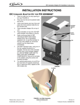
DIMENSION DRAWING
WCC500 & WCC700 SERIES
Figure 1.
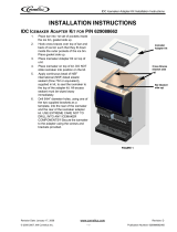
WCC 700R
Figure 1A.

Continuous Flow Icemaker Installation Manual
© 2004-2019, Cornelius Inc. - 5 - Publication Number: 630460174INS
WCC700R CHUNKLET CARBON
Figure 1B .
WCC 700W CHUNKLET CARBON
Figure 1C .

Continuous Flow Icemaker Installation Manual
Publication Number: 630460174INS - 6 - © 2004-2019, Cornelius Inc.
WCC 700A CHUNKLET CARBON
Figure 1D .
WCC 700R CHUNKLET CARBON (FOR SHORTER UNIT WITH S/N’S STARTING WITH 62Q1930)
Figure 2A .

Continuous Flow Icemaker Installation Manual
© 2004-2019, Cornelius Inc. - 7 - Publication Number: 630460174INS
WCC 700A CHUNKLET CARBON (FOR SHORTER UNIT WITH S/N’S STARTING WITH 62R1914)
Figure 2B.
WCC 700W CHUNKLET CARBON (FOR SHORTER UNIT WITH S/N’S STARTING WITH 62R1924)
Figure 2C.

)*+
,
-
!
.
.
/
3
!!3
"3
"
333
#""
33
'(
33
%
"
0
1
2
&
$
"3
3
Continuous Flow Icemaker Installation Manual
Publication Number: 630460174INS - 8 - © 2004-2019, Cornelius Inc.
WCC 2001R
Figure 3.

Continuous Flow Icemaker Installation Manual
© 2004-2019, Cornelius Inc. - 9 - Publication Number: 630460174INS
INSTALLATION INSTRUCTIONS
This manual covers unpacking and inspection, selecting location, installing unit, and preparing for operation.
REMOVE ICE MAKER FROM CARTON
Keep unit in the upright position, remove carton and pallet from unit and inspect unit for damage. Upon inspection
of unit, if any damage is found, file a claim with carrier immediately.
CABINET REMOVAL
1. Front Panel - Remove 4 screws and pull forward.
2. Top Panel - Remove screws and lift upward. 4 screws 500/700.
3. Side Panel - Remove 4 screws and pull forward.
4. Back Panel - Should not be removed.
CABINET REMOVAL ALTERNATE
This Sections Pertains to all 700-Series ice makers that contains the carbon front panel.
1. Front Panel - Remove 2 screws along bottom edge of front panel. Lift panel up and pull forward.
2. Top Panel - There are no screws located on the top panel, but it cannot be removed until the front panel has
been removed.
3. Side Panel - Remove all screws and pull forward.
4. Back Panel - Should not be removed.
PREPARATION OF INSTALLATION SITE
The refrigeration system on air cooled units requires airflow, so a well ventilated area should be chosen.
1. A minimum of 12 inches must be maintained, free of any obstructions, for air intake. A minimum of 4 inches
clearance is required for air exhaust.
2. For WCC500A units, maintain minimum clearances of 18 inches on top and 6 inches on sides as well as in
the rear for sufficient air flow.
3. The unit can be installed either on an ice storage bin or ice dispenser using the proper adapter kits. (Refer to
sales literature for information.) The install is kit provided with each ice maker and adapter kits will supply
everything to locate unit correctly. In all cases the ice maker should be sealed all around the base with an
NSF listed sealant. (63804815B)

Continuous Flow Icemaker Installation Manual
Publication Number: 630460174INS - 10 - © 2004-2019, Cornelius Inc.
WATER INLET HOOK-UP
1. Water Inlet - Fitting is a 1/4” (6.35mm) SAE male flare located at the rear of the unit. Connect water supply
with a 1/4” (6.35mm) or larger copper or flexible tubing.
CAUTION:
!
Unit must be installed with only potable water.
NOTE: A shut-off valve with a loop of additional tubing for service is recommended.
2. Water Pressure - Unless otherwise specified, the unit is designed to operate on water pressures between 10
P.S.I. (0.69 MPa) and 90 P.S.I. (0.62 MPa). A recommended water supply is with temperatures between
50° F - 90° F (10° C - 32° C) with a pressure between 20-70 p.s.i (0.138 - 0.48 MPa).
NOTE: For pressures above 90 P.S.I. (0.62 MPa) a regulator must be installed.
NOTE: This equipment must be installed with adequate backflow protection to comply with
applicable federal state and local codes.
3. Filter - IMF (Phosphate Feeder) Water Filters and Scale inhibitors are not recommended for use with the
Continuous Flow Ice-Maker, Taste & Odor only should be used. Total dissolved solids in the water should be
within the below specified limit
Min dissolved solids = 270 PPM(TDS).
Max dissolved solids = 500 PPM(TDS).
NOTE: Water inlet for the Ice Maker should not be with RO Filtration System.
NOTE: Unit must be installed per local plumbing code.
DRAIN CONNECTION
1. Overflow Line - is a 3/8” I.D. flexible tube located at the rear of the unit. Extend this line to proper drain.
2. Condenser Outlet - is a 3/8” FPT located on the rear panel.

Continuous Flow Icemaker Installation Manual
© 2004-2019, Cornelius Inc. - 11 - Publication Number: 630460174INS
ELECTRICAL SUPPLY
1. Power Access - is provided with a 7/8” diameter. knockout hole in the rear panel. Route incoming power in
conduit, through rear panel to ice maker electrical control box. Make connections to wires provided in the con-
trol box and ground lug/screw.
For WCC700A units, 8 ft. 2 inch long (2.4 m) power cord with 3-prong plug attached to the unit.
CAUTION:
!
Only trained and certified electrical technicians should replace the power cord or the unit should be returned to an
Authorized Service Center for power cord replacement. The replacement cord must meet all requirements of the
original equipment manufacturer.
Failure to comply could result in serious injury, death or damage to the equipment
2. Fus
ed Line - should be checked and sized according to electrical rating shown on unit nameplate.
Figure 4. Schematic and Wiring Diagram WCC500-A, WCC500-W, WCC700-A, WCC700-R, WCC700-W

Continuous Flow Icemaker Installation Manual
Publication Number: 630460174INS - 12 - © 2004-2019, Cornelius Inc.
Figure 5. Schematic and Wiring Diagram WCC2001-R
Figure 6. Schematic and Wiring Diagram CR1200

Continuous Flow Icemaker Installation Manual
© 2004-2019, Cornelius Inc. - 13 - Publication Number: 630460174INS
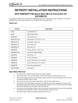
AUGER ENGAGEMENT
Be certain that auger is fully engaged to lower drive and extruder head is fully engaged into evaporator. Perform the
following procedure to engage the auger properly.
1. Install the extruder head on top of the evaporator, as shown in Figure 7.
Auger/
Extruder
Head
Figure 7.
2. When the auger is lowered into the evaporator, rotate the auger to engage the motor drive shaft, as shown in
Figure 8.
Extruder
Evaporator
Head
Figure 8. .
3. Carefully rotate the extruder head until the tabs on the extruder head drop into the slots on the evaporator
plate, as shown in Figure 9.When the auger/extruder head assembly is rotated to the proper position,
it will
drop about 1/4 inch to more fully engage the motor drive shaft.

Continuous Flow Icemaker Installation Manual
Publication Number: 630460174INS - 14 - © 2004-2019, Cornelius Inc.
NOTE: Not all the tabs are the same width. Therefore, you must rotate the auger until all the tabs
are properly aligned with the evaporator slots. This may require almost a complete rotation
of the extruder head to complete.
CAUTION:
!
Keep hands out of the way when rotating the extruder head. When the auger is aligned, it drops down quickly and a
finger may be pinched due to the weight of the auger/extruder head assembly.
Failure to lock the extruder head tabs into the evaporator slots causes the auger to be out of proper alignment with
the evaporator. This may cause excessive loads on the auger that can potentially result in excessive noise and
tripping the drive motor overload.
All tabs &
slots engaged
Figure 9.

Continuous Flow Icemaker Installation Manual
© 2004-2019, Cornelius Inc. - 15 - Publication Number: 630460174INS
INITIAL START UP, CHECKS AND ADJUSTMENT INSTRUCTIONS
NOTE: Do not start unit before completing installation steps on the previous page.
Turn on water supply (if unit is water cooled turn water on t
o condenser also) turn on main power switch (located on
top of electrical box), and make the following system checks:
NOTE: If unit will not start be sure water reservoir is full. Low water safety control must be properly
a
djusted to start and shut down unit. If water level drops below bottom of reservoir, unit
must shut down. Adjustment is made by moving magnet up or down.
Water Level - I
f necessary adjust float by bending float arm up or down as needed, push float assembly down until
unit stops running. Release float and unit will restart. Keep water in reservoir at level line while unit is in operation.
Low Water Safety Control - Adjust
magnet by bending magnet arm as needed to shut unit down if water level
drops below bottom of reservoir.
Bin Control - Place ice ar
ound probe, unit should shut down in one minute. Remove ice from around probe, unit
should start in two minutes.
Figure 10. Ice maker Float Assembly
Water modulating valve (water cooled units only) - Opening point of condenser water modulating valve should
be set to maintain proper operating pressure in the refrigeration system high side. Closing point of valve should be
set low enough to close valve during compressor stand by periods. To raise, turn counterclockwise, to lower turn
clockwise.
NOTE: If any of these checks or adjustments cannot be achieved, refer to Service Manual or call for
fa
ctory assistance at 1-800-238-3600.
For WCC2001QT-R Only:
1. The WCC2001QT-R is equipped with a compressor start delay. The auger motors will run before compressor
start for approximately two minutes. This is to clear out the evaporators and is normal.
2. The WCC2001QT-R is equipped with
an auger motor run delay. The auger motors will run after compressor
shut down for approximately two minutes. This is to clear out the evaporators and is normal.

Continuous Flow Icemaker Installation Manual
Publication Number: 630460174INS - 16 - © 2004-2019, Cornelius Inc.
MOUNTING CHUNKLET ICE MAKER ON A
CORNELIUS DISPENSER
DESCRIPTION OF POTENTIAL ISSUE
There may be multiple issues that will affect this continuous run situation. The WCC700R is factory equipped with a
mechanical thermostat and an electronic thermostat that must be set up according to the bin application
instructions. Both thermostats must be set up per factory guidelines.
Corrective Action
Ensure that the mechanical and electronic thermostats are set up properly, with the mechanical thermostat acting
as the primary control. Please refer to our WCC Installation Manual for proper set up of both of the thermostat
controls.
Additional Information
NOTE: Proper dispensing of Chunklet, cube let, or nugget ice from a Cornelius Ice/Bev Combo
dispenser is dependent on proper set-up of the Beverage Dispenser, and proper set-up of
the Chunklet ice maker. Please refer to Cornelius Soft Ice Dispensing Tips for specific set
up instructions.
If your ice maker comes with both an electronic control and a mechanical control:
• The mechanical control should be set up as the primary control.
• The mechanical control should be positioned 4-6" below the top of the ice bin.
• The electronic control should be set up as the secondary control.
• The electronic control should be positioned 2" above the mechanical control.
If your ice maker comes with just an electronic control:
• The electronic control should be positioned according to the instructions included with the extended drop
tube kit.
• Please reference the Soft Ice Dispensing Tips for specific drop tube extension kits needed for various
models of Cornelius dispensers.
Compressed Flaked Ice Adjustments
• Off Cycle Agitation
• Ice Diverter
• Restrictor Plate
• Ice Slide
• Ice Bin Level Setting
• Water Quality Water Filtration
/