Page is loading ...

Self-Contained Flaked Ice Maker Installation Instructions
© 2004-2014, Cornelius Inc. - 1 - Publication Number: 166240010INS
INSTALLATION INSTRUCTIONS
SELF-CONTAINED FLAKED ICE MAKER
SERIES 200, 525, 725 (R404A REFRIGERANT)
IMPORTANT: It is the responsibility of the Installer to ensure that the water supply to the
dispensing equipment is provided with protection against backflow by an air gap as defined in
ANSI/ASME A112.1.2-1979 or an approved vacuum breaker or other such methods as proved
effective by test.
Water pipe connections and fixtures directly connected to a potable water supply shall be sized,
installed, and maintained according to Federal, State, and Local Codes.
You will get better service from the ice machine, longer life and greater convenience if you choose its
location with care.
Here are a few points to consider:
1. Select a location as close as possible to where you are going to use the ice.
2. Allow a minimum of 6” space at sides and rear of machine for ventilation.
3. A kitchen installation is not desirable as a rule. If a kitchen installation is necessary, locate the
machine as far away
from the cooking area as possible. Grease laden air will form greasy deposits on the condenser.
This reduces the ice making efficiency and necessitates thorough cleaning quite often.
4. If you install the unit in a storeroom, be sure the room is well ventilated.
NOTE: Do not install where the ambient and incoming water temperature will drop below 50F or
rise to over 100F.
NOTE: If water pressure exceeds 50 lbs., a water pressure regulator should be installed in water
inlet line between water shut-off valve and strainer. Minimum incoming water pressure required is
22 lbs.
A. Uncrate the unit by removing the staples or nails from the bottom of the carton and lift off.
B. Remove the bolts holding the skid to the machine.
C. If legs are used, adjust the leveling legs of the storage bin until the unit is level and all four (4)
legs are in solid contact with the floor. Leveling is very important to obtain proper draining.
D. Provide a cold water supply line to the area selected for the installation of the unit. The incoming
water line should have a shut-off valve provided at a convenient location close to the ice maker.
The water strainer provided with the unit should be installed on the down-stream side of the
shut-off valve. The supply line must be adequately sized to compensate for the lengths of the
incoming water run. The machine is equipped with a 3/8” male flare connection for the incoming
water line.
NOTE: ALWAYS FLUSH OUT WATER LINES BEFORE STARTING UNIT.
Water cooled units have a water regulating valve that is factory set to operate at 270 to 310 PSIG head
pressure for R404a (water outlet temp. approx. 105F) This should be checked at the time the unit is
being installed.
Two water inlet connections are provided on water cooled units, one for the ice making (evaporator)
section, the other is for the water cooled condenser. Both connections are 3/8” male flare fittings. Inlet
water to the condenser will go to the water regulating valve first, then to the condenser coil and out the
drain.
The reason for separate water inlet connections is that some installations use a water tower for cooling
the water used in the water cooled condenser and some installations use treated water for the ice making
inlet water.
A separate drain will be required for the outlet of the water cooled condenser.
Revision Date: April 01, 2014 www.cornelius.com Revision: B

Self-Contained Flaked Ice Maker Installation Instructions
Publication Number: 166240010INS - 2 - © 2004-2014, Cornelius Inc.
E. Provide a suitable trapped open drain as close as possible to the area where the ice maker is
going to be installed. This may be an existing floor or a 1 1/4” trapped open drain. Connect the
drain line to the rear of the unit and run it with a good fall to the open drain. All plumbing must be
installed according to local codes. The storage bin drains by gravity, and therefore the drain line
must maintain a gradual slope to an open drain and should be insulated.
NOTE: IN SOME CASES IT MAY BE NECESSARY TO INSULATE THE WATER SUPPLY LINE AND
DRAIN LINE. CONDENSATE DRIPPING TO THE FLOOR CAN CAUSE SERIOUS STAINING OF
CARPETS OR HARDWOODS.
F. Connect a drain hose to the condensate drain stub tube.
NOTE: All plumbing must be done in accordance with national and local codes.
G. Connect the electrical supply line to the unit.
NOTE: Make sure the proper voltage and number of wires are provided. See serial plate for this
information.
NOTE: All wiring must conform to national and local codes.
H. Turn on water supply and observe the water level in evaporator sections which should be no
less than 1/4” below the inclined discharge chute opening of the shell.
I. Turn machine on and check for proper voltage and amp draw on the entire unit as well as
components such as the gearmotor and fan motor.
J. Check refrigerant circuit and all plumbing connections for leaks, etc.
K. Check bin thermostat or mechanical shut-off for proper operations. In the mid-range the bin
thermostat will open at 42 and has a 6 differential.
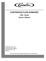
Adjustment Procedure
Water level must be maintained at the top of the evaporator.
FIGURE 1. Water level adjustment procedure
1. Remove gearmotor and auger.
2. Adjust float valve to get water level to top seam of the evaporator.
3. Re-install auger. WATER LEVEL WILL RISE WHEN AUGER IS INSERTED BUT WHEN THE
MACHINE IS TURNED BACK ON AND ICE STARTS BEING MADE, THE WATER LEVEL WILL
GO BACK TO THE ORIGINAL SETTING.
4. Re-install gearmotor assembly and start machine.
WATER LEVEL

Self-Contained Flaked Ice Maker Installation Instructions
© 2004-2014, Cornelius Inc. - 3 - Publication Number: 166240010INS
Typical Water Circuit
The supply water enters the float chamber through a small orifice. The water level rises and lifts the
buoyant float with it. The float attached to the float arm seats a valve to shut off any further water supply.
As water leaves the float chamber, the level drops along with the float and arm, causing the valve to open
and admit more water. Thus the water level is maintained automatically as the machine operates.
Water now flows through a hose connected to the float chamber and enters the opening of the
evaporator shell. The water level in the shell will rise to the same level that is maintained in the float
chamber. The water that is in immediate contact with the center post evaporator will be reduced in
temperature. As a result, freezing occurs and ice forms on the surface of the evaporator.
As more water is frozen, the thickness of the ice increases until it exceeds the distance allowed between
the evaporator and auger. The auger rotates at a slow speed to wipe off the accumulated ice as well as
help it to the surface. After the ice reaches the surface it is discharged through the top opening in the
shell. An ice chute attached to the shell conveys the ice to the storage bin where it accumulates in the
insulated bin until it is used. The ice will pile up to a point where the bin thermostat tubing is located.
When the ice touches this brass tubing, the unit will shut-off and remain off until enough ice is used or
melted to reduce the pile. Any ice that melts will pass through the drain and drain hose to an open drain.
FIGURE 2. typical water circuit
OUT
ICE
EVAPORATOR
CHAMBER
FLOAT
CHAMBER
WATER IN

Self-Contained Flaked Ice Maker Installation Instructions
Publication Number: 166240010INS - 4 - © 2004-2014, Cornelius Inc.
Typical Refrigerant Circuit
Heat always flows from hot to cold and therefore, the ”heat load” supplied to the evaporator section by
water gives up its heat to the refrigerant which is at a temperature below the freezing point of water. This
refrigerant now passes through the heat exchanger back to the compressor, as a low pressure vapor.
This low pressure vapor is compressed in the compressor, as it leaves the compressor at a high pressure
in vapor form it enters the top of the condenser. The condenser has a rapid flow of cool air across it which
removes much of the heat from the hot refrigerant vapor.
As the vapor, passing through the condenser, loses heat it condenses back to a liquid since it is still
under high pressure and cooler than when it entered the condenser. The liquid refrigerant then passes
through the drier/filter still under pressure and goes through the heat exchanger where further cooling
takes place. As the refrigerant leaves the automatic expansion valve, the pressure has dropped, causing
the refrigerant to vaporize and boil off as it picks up heat in the evaporator and since the pressure is low,
the refrigerant will be cold.
FIGURE 3. Typical refrigerant circuit
HEAT
EXCHANGER
EVAPORATOR
CONDENSER
COMPRESSOR
DRIER/FILTER
AXV
/