Page is loading ...

WCC1000/WCF1100 Series Retrofit Installation Instructions
© 2008, IMI Cornelius Inc. - 1 - Publication Number: 631500319INS
RETROFIT INSTALLATION INSTRUCTIONS
WCC1000/WCF1100 SERIES GEAR MOTOR CONVERSION KIT
(631500319)
The purpose of this kit is to convert a WCC1000/WCF1100 to the current gear motor assembly. This requires
updating some of the exterior panels to accommodate the new, larger motor.
Parts List:
Gear Motor Removal
1. Disconnect the icemaker from the power and water supplies.
2. Remove the Top, Front, and Side panels in that order. Retain the side panels for reuse.
3. Remove the dispense tray cover and pull the auger assembly out of the evaporator. Set the cover
and auger assembly aside for reuse.
4. Disconnect the gear motor power transmission cable from the electrical box.
5. Remove the 4 hex head bolts and washers securing the base of the evaporator to the top of the
gear motor transmission. Set the 4 bolts and washers aside for reuse. Gently pry the base upward
and lift the evaporator off of the gear motor transmission.
6. Remove the 4 bolts holding the gear motor transmission and bracket to the frame, while supporting
the weight of the evaporator. Set the 4 bolts and washers aside for reuse.
7. Remove the gear motor and bracket assembly from the unit.
Part No. Description
01022 Lock Washer (4)
02543 3/8-16 Hex Bolt (4)
638004441 Lower Spacer (2)
638007301-030 Flat Washer 2 in. OD X 1 in. ID
638007972-02 Screw #10 x 3/4 in. (2)
638036002-01 Front Panel, SS
638036004-01 Top Panel, SS
638036042 O-Ring, 3/16 in. x 2-3/4 in. ID
638090000-001 Gear Motor 230V/50-60Hz
638090051 Shaft Seal, 1 in.
638090053 E-Ring, Retaining
638090315 Mount, Shaft Seal, 3.5 in. D-Drive
638090316 Seat, Shaft Seal, 3.5 in. D-Drive
638090349 Motor Mounting Bracket
631500319INS Instructions
Release Date: July 28, 2008 www.cornelius.com Revision: A

WCC1000/WCF1100 Series Retrofit Installation Instructions
Publication Number: 631500319INS - 2 - © 2008, IMI Cornelius Inc.
Bracket and Seal Assembly
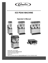
1. Assemble the gear motor to auger seals to match the diagram shown in Figure 1.
2. Carefully install the O-ring onto the shaft seal mount, taking care to not cut or score the surface.
Coat the O-ring with NSF food grade O-ring lubricant.
3. Place the shaft seal seat and shaft seal mount over the gear motor output shaft and push down until
the shaft seal seat and shaft seal mount rest flush on top of the gear motor transmission housing.
4. Place the rubber coated ceramic seal (IMPORTANT! Ceramic face MUST BE UP!) over the output
shaft and push down until the seal nests in the recess of the shaft seal mount. Lubricate the rubber
on the ceramic seal with rubber lubricant.
5. Place the shaft seal with the carbon face down (spring up) over the output shaft and push it gently
downward until the seal rests on the carbon face of the output shaft seal.
6. Place the flat washer over the output shaft and let it rest on the output shaft seal. Push down on the
washer, compressing the spring on the output shaft seal. While holding the seals down in place,
slide the e-ring into the groove on the output shaft.
7. Install the mounting bracket to match the appearance of the one removed.
Figure 1. Front End Assembly, 1000 Series
Gear Motor Replacement
1. Replace the gear motor in the unit, while supporting the weight of the evaporator.
2. Reinstall the 4 bolts holding the gear motor transmission and bracket to the frame.
3. Gently lower the evaporator over the seals and onto the gear motor transmission. Reinstall the 4
hex head bolts securing the base of the evaporator to the top of the gear motor transmission.
4. Make sure the gear motor is secured to the unit and the evaporator is secured to the gear motor.
5. Lower the auger assembly down into the evaporator and make sure the auger engages the gear
motor output shaft. Replace the dispense tray cover.
6. Reconnect the gear motor power transmission cable to the electrical box.
7. Reconnect the icemaker to the power and water supplies. Verify all connections are secure.
8. Test the unit for proper operation.
9. Replace existing side covers and then the new top and front covers.
/