Page is loading ...

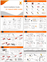
XTE SERIES SINGLE PHASE QUICK GUIDE
XTE SERIES
HYBRID INVERTER
Single Phase
Whole Power Range
WECO 5K3-XP /4K4-LT / 4K5 ULTRA LV
&
XTE SERIES Hybrid 220Vac Single Phase Inverter
Quick Configuration Guide
4
4 LT

XTE SERIES SINGLE PHASE QUICK GUIDE
XTE Series Single Phase Inverter Configuration
Preparations:
Open the connection lid to access the connection board of the inverter, CAN port, CT terminal ad Battery Power Connection
Terminal are all located here.
General Connection Layout
Load Connection Grid Connection
Battery Connection PV Connection
Signal Connection
Port
Name
description
1
CAN1
Used to connect the communication interface between inverters for parallel connection
2
CAN2
Used to connect the communication interface between inverters for parallel connection
3
RS485
Read the internal data of the inverter. Internal use, reserved
4
CAN
BMS communication for lithium batteries
5
CT-L2
For external grid side CT to detect current size. Use of split-phase connection
6
CT-L1
For external grid side CT to detect current size. Single-phase 220V applications only
connect to this CT, split phase connections use CT-L1 and CT-L2
7
Type-C
Local monitoring and upgrading ports

XTE SERIES SINGLE PHASE QUICK GUIDE
Inverter Connection Hub
CT communication Line
CT connection: CT is connected to the RJ45 interface of the inverter end via a network cable. The arrow
direction of the CT points towards the power grid. For single phase application connect the CT RJ45 to the
CT-L1 (6) port.
CT ARROW DIRECTION
TO THE GRID
RJ45 CT
COMMUNICATION
COMMON GROUND
BAR
CT-L1 PORT

XTE SERIES SINGLE PHASE QUICK GUIDE
Step 1. Safety Preparation
For Safety reason it is forbidden to install any power inputs such as PV, GRID or BATTERY before having
completed all the data wiring connection as explained below.
• The PV cables cannot be connected at this stage.
• Grid wires cannot be connected at this stage.
• Battery must keep OFF while performing the connection operations, power cables to be
connected at last.
• Ground the Inverter immediately after fixing it on the wall.
KEEP THE INVERTER OFF
GROUND THE INVERTER

XTE SERIES SINGLE PHASE QUICK GUIDE
Step 2. Battery Preparation
5K3 XP
Set the DIP Switch of the battery in accordance with the manual, in this case the battery is single, the
DIP switched are set all OFF (00000000).
Connect the battery side RJ45 of the supplied CAN cable to the CAN-A port on the battery.
Connect the inverter side RJ45 of the supplied CAN cable to the CAN (4) port of the inverter.
Do not connect the power cables at this point.
Keep the BMS switch on “0” OFF.
4K4LT:
Set the DIP Switch of the battery in accordance with the manual, in this case the battery is single, the
DIP switched are set all OFF (00000000)
Connect the battery side RJ45 of the supplied CAN cable to the CAN-A port on the battery.
Connect the inverter side RJ45 of the supplied CAN cable to the CAN (4) port of the inverter.
Do not connect the power cables at this point.
Keep the BMS switch on ``0`` OFF.

XTE SERIES SINGLE PHASE QUICK GUIDE
Communication line connection
BMS CAN wiring is the same for any WeCo battery.
Terminal
Battery Side
RJ45
INVERTER Side
RJ45
GND
PIN 3
CAN-L
PIN 2
PIN 5
CAN-H
PIN 1
PIN 4
THE CABLE SUPPLIED WITH THE INVERTER IS READY TO GO WITH THE CORRECT PIN OUT FROM WECO BATTERIES
TO XTE INVERTER.
IF YOU ARE NOT USING THE SPECIFIC SUPPLIED CABLE YOU NEED TO MODIFY A STANDARD RJ45 CABLE LOCALLY
TO MATCH THE PINOUT.
BATTERY SIDE KEEP THE
ORIGINAL RJ45 TERMINAL
INVERTER SIDE MAKE A
NEW TERMINAL PIN OUT

XTE SERIES SINGLE PHASE QUICK GUIDE
Multiple batteries connected in parallel with inverter
Master and Slave configuration of 5K3XP and 4K4LT can be done up to 15 batteries without accessories
From the Master to the penultimate battery the DIP SWITCH to be set all OFF
The last battery must have the DIP 6 ON to enable 485 communication for battery parallel connection
For more details follow the batteries manuals
NLPENLPE
L
GRID
N
CT
PE
LOAD
L
N
PE
PV1
PV2
PV1+
PV1-
PV2+
PV2-
PE
B+
B-
CAN-A
1
ON DIP
2 3 4 5 6 7 8
ADDRESS
DO1+
DO1-
DO2+
DO2-
DI1+
DI1-
DI2+
DI2-
RS485-B CAN-B OPERATOR
RS485-A CAN-A
B+ B+ B- B-
OFF
ON
1
ON DIP
2345678
MASTER
1
ON DIP
2 3 4 5 6 7 8
ADDRESS
DO1+
DO1-
DO2+
DO2-
DI1+
DI1-
DI2+
DI2-
RS485-B CAN-B OPERATOR
RS485-A CAN-A
B+ B+ B- B-
OFF
ON
1
ON DIP
2 3 4 5 6 7 8
SLAVE 1
1
ON DIP
2 3 4 5 6 7 8
ADDRESS
DO1+
DO1-
DO2+
DO2-
DI1+
DI1-
DI2+
DI2-
RS485-B CAN-B OPERATOR
RS485-A CAN-A
B+ B+ B- B-
OFF
ON
1
ON DIP
2 3 4 5 6 7 8
SLAVE 2
1
ON DIP
2 3 4 5 6 7 8
ADDRESS
DO1+
DO1-
DO2+
DO2-
DI1+
DI1-
DI2+
DI2-
RS485-B CAN-B OPERATOR
RS485-A CAN-A
B+ B+ B- B-
OFF
ON
1
ON DIP
2 3 4 5 6 7 8
SLAVE n
DIP6 ON
TERMINATOR
NLPENLPE
L
GRID
N
CT
PE
LOAD
L
N
PE
PV1
PV2
PV1+
PV1-
PV2+
PV2-
PE
B+
B-
CAN-A
1
ON DIP
2 3 4 5 6 7 8
ADDRESS
DO1+
DO1-
DO2+
DO2-
DI1+
DI1-
DI2+
DI2-
RS485-B CAN-B OPERATOR
RS485-A CAN-A
B+ B+ B- B-
OFF
ON
1
ON DIP
2345678
MASTER
1
ON DIP
2 3 4 5 6 7 8
ADDRESS
DO1+
DO1-
DO2+
DO2-
DI1+
DI1-
DI2+
DI2-
RS485-B CAN-B OPERATOR
RS485-A CAN-A
B+ B+ B- B-
OFF
ON
1
ON DIP
2 3 4 5 6 7 8
SLAVE 1
1
ON DIP
2 3 4 5 6 7 8
ADDRESS
DO1+
DO1-
DO2+
DO2-
DI1+
DI1-
DI2+
DI2-
RS485-B CAN-B OPERATOR
RS485-A CAN-A
B+ B+ B- B-
OFF
ON
1
ON DIP
2 3 4 5 6 7 8
SLAVE 2
1
ON DIP
2 3 4 5 6 7 8
ADDRESS
DO1+
DO1-
DO2+
DO2-
DI1+
DI1-
DI2+
DI2-
RS485-B CAN-B OPERATOR
RS485-A CAN-A
B+ B+ B- B-
OFF
ON
1
ON DIP
2345678
SLAVE n
DIP6 ON
TERMINATOR
NLPENLPE
L
GRID
N
CT
PE
LOAD
L
N
PE
PV1
PV2
PV1+
PV1-
PV2+
PV2-
PE
B+
B-
CAN-A
1
ON DIP
2 3 4 5 6 7 8
ADDRESS
DO1+
DO1-
DO2+
DO2-
DI1+
DI1-
DI2+
DI2-
RS485-B CAN-B OPERATOR
RS485-A CAN-A
B+ B+ B- B-
OFF
ON
1
ON DIP
2345678
MASTER
1
ON DIP
2 3 4 5 6 7 8
ADDRESS
DO1+
DO1-
DO2+
DO2-
DI1+
DI1-
DI2+
DI2-
RS485-B CAN-B OPERATOR
RS485-A CAN-A
B+ B+ B- B-
OFF
ON
1
ON DIP
2 3 4 5 6 7 8
SLAVE 1
1
ON DIP
2 3 4 5 6 7 8
ADDRESS
DO1+
DO1-
DO2+
DO2-
DI1+
DI1-
DI2+
DI2-
RS485-B CAN-B OPERATOR
RS485-A CAN-A
B+ B+ B- B-
OFF
ON
1
ON DIP
2 3 4 5 6 7 8
SLAVE 2
1
ON DIP
2 3 4 5 6 7 8
ADDRESS
DO1+
DO1-
DO2+
DO2-
DI1+
DI1-
DI2+
DI2-
RS485-B CAN-B OPERATOR
RS485-A CAN-A
B+ B+ B- B-
OFF
ON
1
ON DIP
2 3 4 5 6 7 8
SLAVE n
DIP6 ON
TERMINATOR
NLPENLPE
L
GRID
N
CT
PE
LOAD
L
N
PE
PV1
PV2
PV1+
PV1-
PV2+
PV2-
PE
B+
B-
CAN-A
1
ON DIP
2 3 4 5 6 7 8
ADDRESS
DO1+
DO1-
DO2+
DO2-
DI1+
DI1-
DI2+
DI2-
RS485-B CAN-B OPERATOR
RS485-A CAN-A
B+ B+ B- B-
OFF
ON
1
ON DIP
2 3 4 5 6 7 8
MASTER
1
ON DIP
2 3 4 5 6 7 8
ADDRESS
DO1+
DO1-
DO2+
DO2-
DI1+
DI1-
DI2+
DI2-
RS485-B CAN-B OPERATOR
RS485-A CAN-A
B+ B+ B- B-
OFF
ON
1
ON DIP
2 3 4 5 6 7 8
SLAVE 1
1
ON DIP
2 3 4 5 6 7 8
ADDRESS
DO1+
DO1-
DO2+
DO2-
DI1+
DI1-
DI2+
DI2-
RS485-B CAN-B OPERATOR
RS485-A CAN-A
B+ B+ B- B-
OFF
ON
1
ON DIP
2 3 4 5 6 7 8
SLAVE 2
1
ON DIP
2 3 4 5 6 7 8
ADDRESS
DO1+
DO1-
DO2+
DO2-
DI1+
DI1-
DI2+
DI2-
RS485-B CAN-B OPERATOR
RS485-A CAN-A
B+ B+ B- B-
OFF
ON
1
ON DIP
2 3 4 5 6 7 8
SLAVE n
DIP6 ON
TERMINATOR
NLPENLPE
L
GRID
N
CT
PE
LOAD
L
N
PE
PV1
PV2
PV1+
PV1-
PV2+
PV2-
PE
B+
B-
CAN-A
1
ON DIP
2 3 4 5 6 7 8
ADDRESS
DO1+
DO1-
DO2+
DO2-
DI1+
DI1-
DI2+
DI2-
RS485-B CAN-B OPERATOR
RS485-A CAN-A
B+ B+ B- B-
OFF
ON
1
ON DIP
2345678
MASTER
1
ON DIP
2 3 4 5 6 7 8
ADDRESS
DO1+
DO1-
DO2+
DO2-
DI1+
DI1-
DI2+
DI2-
RS485-B CAN-B OPERATOR
RS485-A CAN-A
B+ B+ B- B-
OFF
ON
1
ON DIP
2 3 4 5 6 7 8
SLAVE 1
1
ON DIP
2 3 4 5 6 7 8
ADDRESS
DO1+
DO1-
DO2+
DO2-
DI1+
DI1-
DI2+
DI2-
RS485-B CAN-B OPERATOR
RS485-A CAN-A
B+ B+ B- B-
OFF
ON
1
ON DIP
2 3 4 5 6 7 8
SLAVE 2
1
ON DIP
2 3 4 5 6 7 8
ADDRESS
DO1+
DO1-
DO2+
DO2-
DI1+
DI1-
DI2+
DI2-
RS485-B CAN-B OPERATOR
RS485-A CAN-A
B+ B+ B- B-
OFF
ON
1
ON DIP
2 3 4 5 6 7 8
SLAVE n
DIP6 ON
TERMINATOR

XTE SERIES SINGLE PHASE QUICK GUIDE
Step 3. Battery Power Connection
Keep Inverter and Battery OFF
Connecting the power Cables from the battery to the Inverter
Use a Torque Wrench to secure the cables bolt.
Same configuration applies to the 4k4 LT model
Battery Torque: 9,5 Nm
Inverter Torque: 11 Nm
INVERTER OFF
BATTERY OFF

XTE SERIES SINGLE PHASE QUICK GUIDE
Step 4. Battery FW Upgrade and Protocol Set
5K3-XP FW Upgrade and Protocol Set
Download the WeCo Bluetooth APP from Google Play of from APP Store.
The Bluetooth APP will allow you to inspect the battery, set the battery and monitor the BMS functions
during the commissioning phase.
As good Practice it is always required to search for the latest FW for the battery.
The 5k3XP Model has a built in WiFi /BT device and it is possible to find the battery Bluetooth Signal ( in
the form of battery Serial Number) directly from the APP list.
• Open the BT APP
• Turn On the Battery
• Access the APP using the password 1010
• Select Battery Module
• Scroll Down and tap on the Serial Number of your battery
• Once the main page will display your battery info, scroll down and tap on the FW upgrade button if
available( if not displayed means the battery is UP to Date)
APP STEPS
01
02
03
04
05
06

XTE SERIES SINGLE PHASE QUICK GUIDE
Protocol Set Up
Wait until pop up confirms that the update process is successful, then proceed to set the inverter protocol.
4K4-LT Protocol Set
Note:
⚫ The factory default protocol for the 4K4-LT battery module is "WeCoCAN".
⚫ If you need to change the protocol, you can use the previous procedure using a Wifi dongle or the pc
software.
⚫ The new battery will be forcibly charged to SOC=100% when used for the first time.
⚫
UPPER COMPUTER STEPS
Use the RS232 converter cable by connecting the RJ45 side on the “Operator” port of the battery and the
other end connected to the computer USB interface. Then turn on the battery switch and button;
Swipe UP to
reach the bottom
of the Page
SET WecoCAN

XTE SERIES SINGLE PHASE QUICK GUIDE
You can download the last version of the LT monitor software on our website
wecobatteries.com/download-area.
Follow these steps to set up the communication protocol.
ATTENTION
Turn Off the battery to proceed with the remaining operations
Keeping the battery ON will damage the BMS an potentially the inverter power protection circuit

XTE SERIES SINGLE PHASE QUICK GUIDE
Step 5. Inverter Wiring
Now it is possible to wire the GRID, LOAD and PV cables into the inverter and reinstalling the protection
cover.
Then turn on the PV Switch to enable the PV
Now the inverter will Initiate the start Up process and the Battery can be turned ON.
Step 6. APP download and add devices
Download and install the app
⚫ Download method:Search for "Noor" in the Google Play or App Store application market.
⚫ Mobile phone system requirements:It supports use on IOS 12.0 and Android 8.1.0 or above.
Register an account
⚫ Click "Register" below on the Noor App login page.
⚫ Then complete the account registration according to the prompts on the page.
⚫ After the account registration is successful, the user can log in to the Noor App with the registered
account and password.

XTE SERIES SINGLE PHASE QUICK GUIDE
Log in and add a power station
Follow the prompts below to add a power station
Add Devices
⚫ Click the “ ” icon in the upper right corner of the homepage to enter the scanning page.
⚫ Scan or identify the WiFi module QR code (referred to as: SN code) on the inverter and battery to be
connected from the album, if the SN code is damaged or the scanning is abnormal, you can click the “
” icon.
⚫ On the "Add Device" page, fill in the "SN" and "Device Name" information according to the prompts on
the page.
Note:After clicking "Adding" to add successfully, you can choose whether to configure the device:
• If you click "Home page", you can return to the home page.
• If you click "Smart config", you will enter the "Smart Config" page, which has three steps of Bluetooth
pairing, selecting WiFi, and configuring WiFi, and you can complete the device configuration according
to the prompts on the page.

XTE SERIES SINGLE PHASE QUICK GUIDE
Step 7. Inverter settings
Enter the settings page
⚫ Scroll down the main page to the access for Inverter settings and running info.
⚫ Click on the "Inverter Setting" button to view the setting list.

XTE SERIES SINGLE PHASE QUICK GUIDE
Set working mode
In the operation mode selection of the basic setting interface, you can set "Auto Mode", "Peak Shaving ",
and "Battery priority" to make the inverter work in different operation modes.
⚫ Auto Mode: The priority of photovoltaic power generation is to ensure the load works, and then the
remaining photovoltaic power is charged to the energy storage battery. After the battery is fully
charged, the excess energy can be fed into the grid.
⚫ Peak Shaving: The inverter can run according to the set time and power, setting the charging time period
at a time when the electricity price in the current region is low, and set the discharge time at a time
when the electricity price in the current region is high, will save you more costs.
⚫ Battery Priority: In this mode, power will be taken from the photovoltaic or power grid until the battery
is fully charged. The battery will be discharge to meet the load request only when there is no other
power source available.
Set Sys Setting
Settable functions: Date, Time, EPS enable,PV Input Type, ARC enable, Anti reflux,CT Ratio.
⚫ Date: Current date. The inverter's statistical function will be performed based on this set date.
⚫ Time: The current time, the system's planning mode, will match this set time.
⚫ EPS Enable: EPS enable switch. After setting the enable switch, the load will output and provide power
after the inverter is off the grid.
⚫ PV Input Type: Photovoltaic input type, default to independent input.
⚫ ARC Enable: US test standards need to be set to enable.
⚫ Anti Refulex: Discharge the reverse current and set the enable so that the excess energy of the system
will not be fed back to the power grid.
⚫ Ct Ratio: Transformation ratio of external current transformer for detecting current, multiple of A/A.

XTE SERIES SINGLE PHASE QUICK GUIDE
Battery Setting
Settable functions: Bat Grid DOD, Off Grid DOD, Soc Threshold Hysteresis:
⚫ Bat Grid DOD: The lower limit of the discharge SOC On grid connection operation. When it is lower than
this value, the battery will no longer discharge.
⚫ Off Grid DOD: The lower limit of the discharge SOC during off-grid operation. When it is lower than this
value, the battery will no longer discharge.
⚫ Soc Threshold Hysteresis: After discharging to the SOC value that needs to be charged after the
protection is effective, otherwise it will not be discharged here.
Grid setting
Settable functions: Grid Standard, Grid Set, American Standard Classification.
⚫ Grid Standard: Select the national grid standard, and after confirmation by the state, the voltage
amplitude and frequency will be determined
⚫ Grid Set: Set whether it is a single output or two outputs
⚫ American Standard Classification: Selection of grid standards used in different regions of the United
States.

XTE SERIES SINGLE PHASE QUICK GUIDE
Parallel setting
Settable functions: Inv Parallel Num, Parallel Master/Slave, Inv Parallel Addr, Common Battery Enable,
Common GridCT Enable, 3 Phase Enable, Phase of this machine, Parallel Charge Current, Parallel Discharge
Current, Inv Parallel Enable.
⚫ Inv Parallel Num: Number of parallel machines.
⚫ Parallel Master/Slave: Whether the parallel identity is a host or a slave, the slave will work according to
the host's command.
⚫ Inv Parallel Addr: Parallel address. In a parallel system, the address cannot be repeated and can be set
between 1-99.
⚫ Common Battery Enable: Whether the battery is shared in the parallel system.
⚫ Common GridCT Enable: In the parallel system, whether the current transformer on the grid side is
shared.
⚫ 3 Phase Enable: Whether the parallel system constitutes a three-phase power grid.
⚫ Phase of this machine: Set the phase connected to the selected inverter.
⚫ Parallel Charge Current: Limit of charging current to the battery after parallel operation.
⚫ Parallel Discharge Current: Discharge current limit for battery after the parallel operation.
⚫ Inv Parallel Enable: The parallel setting will not take effect until the parallel setting is enabled.

XTE SERIES SINGLE PHASE QUICK GUIDE
Generator setting
Settable functions: Generator Start SOC, Generator Stop SOC, Generator Charge Current, Maximum
Operating Time, Generator Cooling Time, Generator Enable, Generator Charge Enable, Generator Auto
Start, Generator Manual On, Generator Manual CMD, Generator Connect Grid, Generator Power.
⚫ Generator Start SOC: The generator automatically starts the SOC value. After the battery SOC is lower
than this value, if the generator enable is set to enable, the generator start dry connection point will
close to start the generator.
⚫ Generator Stop SOC: The generator automatically stops the SOC value. After the battery SOC is higher
than this value, if the generator enable is set to enable, the generator start dry connection point will be
disconnected and the generator will be shut down.
⚫ Generator Charge Current: The current value for charging the battery after the generator is started.
Please pay attention to the generator power and load power when setting this value.
⚫ Maximum Operating Time: Maximum operating time after generator startup.
⚫ Generator Cooling Time: Cooling time for generator shutdown.
⚫ Generator Enable: The generator is enabled, and the startup and shutdown of the generator will not
take effect until the enable setting is set.
⚫ Generator Charge Enable: Generator charging is enabled, and the battery will not be charged until the
generator is started after setting the enable.
⚫ Generator Auto Start: Control the dry contact and enable the signal of the external generator.
⚫ Generator Manual On: Manual control generator enable signal.
⚫ Generator Manual CMD: Manually control the generator on and off.
⚫ Generator Connect Grid: The externally connected generator is connected to the power grid input
terminal for use.
⚫ Generator Power: Generator power, is not less than system load power.

XTE SERIES SINGLE PHASE QUICK GUIDE
Advanced setting
Click on the "Inverter Setting" button in the slide-out page to view the Setting list;
On the basic settings page, slide your finger to the left to enter the advanced settings page:
⚫ Inverter AC Power:Grid connected power dispatching, taking power from the grid and feeding back
the maximum power value of the grid, using percentage settings.
⚫ Bat Discharge Power:Battery discharge power scheduling, maximum power value of battery discharge,
usage percentage setting.
⚫ Bat Charge Current:Battery charging current.
⚫ Restore Factory Setting:Restore factory settings.
⚫ Remote Start UP/ShutDown:System power-on and power-off settings.
https://wecoess.com/download-area/
/