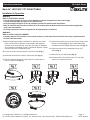
MaxLite ML2LASP Series is a versatile and energy-efficient LED lighting solution that offers customizable color temperature, adjustable motion sensor settings, and various dimming options. With itscct selectable feature, you can choose between different color temperatures, ranging from warm white to cool white, to create the desired ambiance for your space.
MaxLite ML2LASP Series is a versatile and energy-efficient LED lighting solution that offers customizable color temperature, adjustable motion sensor settings, and various dimming options. With itscct selectable feature, you can choose between different color temperatures, ranging from warm white to cool white, to create the desired ambiance for your space.


-
 1
1
-
 2
2
-
 3
3
-
 4
4
-
 5
5
-
 6
6
-
 7
7
-
 8
8
-
 9
9


MaxLite ML2LASP Series is a versatile and energy-efficient LED lighting solution that offers customizable color temperature, adjustable motion sensor settings, and various dimming options. With itscct selectable feature, you can choose between different color temperatures, ranging from warm white to cool white, to create the desired ambiance for your space.
Ask a question and I''ll find the answer in the document
Finding information in a document is now easier with AI
Related papers
-
MaxLite ML2LASA Series User manual
-
MaxLite LSU4U23WCSCR User manual
-
 MaxLite RCF832WCSDW User manual
-
MaxLite ML9LAABN23CS User manual
-
MaxLite WPC20UT4-CSBPCCR User manual
-
-
MaxLite MXL-108611 User manual
-
 MaxLite DBL Series LED Dusk-To-Dawn Barn Light Fixture User manual
-
 MaxLite Classic Series User manual
-
 MaxLite SECS15UCSBPC User manual


Other documents
-
Superior Life PQL-55353 User manual
-
AFX OSCF11LAJD1SN User manual
-
 LED Lighting ML8LA Series MaxLite LED Architectural Vanity Bar User manual
-
RAB Flush Mount Operating instructions
-
RAB Lighting 11R-16-9CCT User manual
-
LED Lighting MSF Series User manual
-
ESPEN VRF-DR User manual
-
Sunco Lighting LED Ceiling Panel Light User manual
-
 merrytek MC054V- RC- 2A User manual
-
Sunco Lighting WP-80W-5K-1PK User manual

