LED Lighting MSF Series User manual

Type
User manual

LED Lighting MSF Series fixtures are designed for both commercial and residential use, providing energy-efficient lighting solutions for various applications. With a range of wattages from 15W to 140W, these slim flood fixtures offer adjustable color temperature and, for select models, wattage adjustment. Installation options include a ½ NPT knuckle mount, yoke mount, or slipfitter mount, allowing for flexible placement. The fixtures are suitable for use in wet locations and feature built-in surge protection for added safety.

LED Lighting MSF Series fixtures are designed for both commercial and residential use, providing energy-efficient lighting solutions for various applications. With a range of wattages from 15W to 140W, these slim flood fixtures offer adjustable color temperature and, for select models, wattage adjustment. Installation options include a ½ NPT knuckle mount, yoke mount, or slipfitter mount, allowing for flexible placement. The fixtures are suitable for use in wet locations and feature built-in surge protection for added safety.

To reduce the risk of death, personal injury or property damage from
fire, electric shock, falling parts, cuts/abrasions, and other hazards
read all warnings and instructions included with and on the fixture
box and all fixture labels.
• Before installing, servicing, or performing routine maintenance upon
this equipment, follow these general precautions.
• Commercial installation, service and maintenance of luminaires
should be performed by a qualified licensed electrician.
• For Residential installation: If you are unsure about the installation or
maintenance of the luminaires, consult a qualified licensed electrician
and check your local electrical code.
• DO NOT INSTALL DAMAGED PRODUCT!
This fixture is intended to be connected to a properly installed and
grounded UL listed junction box.
WARNING:
• Risk of Fire - Supply conductors (power wires) connecting the fixture
must be rated min. 75°C Supply Conductors. If uncertain consult an electrician.
• Risk of fire or electric shock. installation requires knowledge of
luminaires electrical systems.
• Risk of Fire/Electric Shock - If not qualified, do not attempt installation. Contact a qualified electrician.
• Do not use in high humidity conditions.
• Keep away from flammable and explosive environment.
• Don’t cover the fixture with insulation liner or similar material.
• Don’t install where fixture is loose or only partially supported.
• Don’t impact or exert pressure on the fixture surface face or rear, as damage may occur.
CAUTION:
• For your safety read and understand instructions completely before starting installation.
To prevent wiring damage or abrasion, do not expose wiring to edges of sheet metal or other sharp
objects.
• Before attempting installation, check your local electrical code, as it
sets the wiring standards for your locality.
NOTES:
• If luminaire (fixture) is to be switched from a wall switch, make sure black power supply wire is
connected to the switch. DO NOT connect the white supply wire to the switch.
• Make certain no bare wires are exposed outside the wire nut connectors.
• Do not make or alter any open holes in an enclosure of wiring or electrical components during
kit installation.
Model:
MSF Series
© Copyright 2022. MaxLite, Inc. All Rights Reserved.
12 York Ave, West Caldwell, NJ 07006 Tel: 800-555-5629 Fax: 973-244-7333 Email: info@maxlite.com
Page: 1
REV: 03/15/22
General Safety Information
Operating Instructions MSF Series
MaxLite LED Slim Flood Fixtures (15W-140W)
®
Picture is for illustration purposes only.
Your model may vary.
© Copyright 2022. MaxLite, Inc. All Rights Reserved.
12 York Ave, West Caldwell, NJ 07006 Tel: 800-555-5629 Fax: 973-244-7333 Email: info@maxlite.com
Page: 2
REV: 03/15/22
General Wiring Diagram
CAUTION: Turn off electrical power at fuse or circuit breaker box before wiring fixture to the
power supply.
0-10V Dimmable Wiring:
1.) Connect the black fixture wire to the HOT LINE supply wire.
2.) Connect the white fixture wire to the NEUTRAL supply wire.
3.) Connect the green fixture wire to supply ground wire.
4.) Connect the purple fixture wire to the (V+) DIM wire.
5.) Connect the pink fixture wire to the (V-) DIM wire.
Operating Instructions MSF Series
MaxLite LED Slim Flood Fixtures (15W-140W)
®
1.) Remove the luminaire from the packaging.
2.) Connect the AC input wires coming from the mounting bracket to the power supply wires (Fig. 1).
½ NPT Knuckle Mount (15W, 25W, 60W Only)
© Copyright 2022. MaxLite, Inc. All Rights Reserved.
12 York Ave, West Caldwell, NJ 07006 Tel: 800-555-5629 Fax: 973-244-7333 Email: info@maxlite.com
Page: 3
REV: 03/15/22
1/2 Knuckle Mount
Pink
3.) Loosen the screw in the center of the mounting bracket and adjust it to the desired angle.
Retighten the screw (Fig. 2).
4.) Insert the ½” threaded nipple into the mounting surface (pole, junction box, etc.). Ensure that it is secure by
either screwing it into the mounting surface or with the supplied nut (Fig. 3).
Operating Instructions MSF Series
MaxLite LED Slim Flood Fixtures (15W-140W)
®
© Copyright 2022. MaxLite, Inc. All Rights Reserved.
12 York Ave, West Caldwell, NJ 07006 Tel: 800-555-5629 Fax: 973-244-7333 Email: info@maxlite.com
Page: 4
REV: 03/15/22
1.) Remove the luminaire from the packaging.
2.) If there is an existing mounting bracket, other than the yoke mount (i.e. knuckle mount), remove it from the
fixture (Fig. 4).
Yoke Mount (All Models)
3.) Attach the yoke bracket to the fixture using two (2) included bolts (Fig. 5).
4.) Drill two (2) holes into the mounting surface using the yoke mount as a template (Fig. 6).
5.) Insert expansion bolts (anchor bolts) into the holes drilled in step 4 (Fig. 7).
Expansion Bolt
L
6.) Attach the yoke bracket to the surface, loosen the bolts on both sides of the yoke, and adjust the luminaire to
the desired angle. Secure the luminaire in this position by tightening the bolts on both sides of the yoke
(Fig. 8).
7.) Connect the AC input wires coming from the mounting bracket to the power supply wires (Fig. 9).
Pink
Operating Instructions MSF Series
MaxLite LED Slim Flood Fixtures (15W-140W)
®
© Copyright 2022. MaxLite, Inc. All Rights Reserved.
12 York Ave, West Caldwell, NJ 07006 Tel: 800-555-5629 Fax: 973-244-7333 Email: info@maxlite.com
Page: 5
REV: 03/15/22
1.) Remove the luminaire from the packaging.
2.) Connect the input wires coming out of the mounting bracket to the power supply wires (Fig. 10). Place the
wires into the pole and place the mount onto the pole. Secure the mount onto the pole by tightening the
locking bolts.
3.) Loosen the screw in the center of the mounting bracket and adjust it to the desired angle. Retighten the
screw (Fig. 11).
Slipfitter Mount (105W, 140W Only)
Pink
1.) Remove the metal and plastic KO plugs from the top of the fixture (Fig. 12)
Installation & Operation – Color Temperature (CCT)/Wattage Adjustment & PC Controller
2.) Adjust the color temperature controller to the desired CCT, the power controller to the desired wattage
(-WCS models only), and the photocell controller on or off (Fig. 13).
Photocell and Power Controller
Color Controller
5K
4K
3K
H
M
L
3.) Replace the KO plugs, ensure they are tight to prevent any ingress water. The clear plastic plug should be
used on the hole with the photocell controller (Fig. 14).
Operating Instructions MSF Series
MaxLite LED Slim Flood Fixtures (15W-140W)
®
MaxLite Inc. warrants its products for a minimum period of FIVE (5) years from the date of original purchase from
MaxLite or its authorized distributor/dealer (the “Warranty Period”), as follows: If a Product fails to operate during the
Warranty Period as a result of defects in materials or workmanship, MaxLite will, at its option, repair it, replace it with
the same or like Product.
Please refer to Maxlite’s website (at http://maxlite.com/resources/warranties) for the complete
terms and conditions of our warranty.
Limitation of Liability
THE FOREGOING WARRANTY IS EXCLUSIVE, AND IS THE SOLE REMEDY FOR ANY AND ALL CLAIMS,
WHETHER IN CONTRACT, IN TORT OR OTHERWISE ARISING FROM THE FAILURE OF PRODUCT AND IS IN
LIEU OF ALL OTHER WARRANTIES, EXPRESS OR IMPLIED, INCLUDING ALL WARRANTIES OF
MERCHANTABILITY OR FITNESS FOR A PARTICULAR PURPOSE, WHICH WARRANTIES ARE HEREBY
EXPRESSLY DISCLAIMED TO THE EXTENT PERMITTED BY LAW AND, IN ANY EVENT, SHALL BE LIMITED TO
THE WARRANTY PERIOD SPECIFIED ABOVE. THE LIABILITY OF MAXLITE SHALL BE LIMITED TO THE TERMS
OF THE EXPRESS WARRANTY SET FORTH HEREIN. IN NO EVENT WILL MAXLITE BE LIABLE FOR ANY
SPECIAL, INCIDENTAL OR CONSEQUENTIAL DAMAGES INCLUDING, WITHOUT LIMITATION, DAMAGES
RESULTING FROM LOSS OF USE, PROFITS, BUSINESS OR GOODWILL, LABOR COSTS, REMOVAL OR
INSTALLATION COSTS, DECREASE IN THE LIGHT OUTPUT OF THE LAMP, AND/OR DETERIORATION IN THE
LAMP’S PERFORMANCE, WHETHER OR NOT MAXLITE HAS BEEN ADVISED OF THE POSSIBILITY THEREOF.
UNDER NO CIRCUMSTANCES SHALL MAXLITE’S ENTIRE LIABILITY FOR A DEFECTIVE PRODUCT EXCEED
THE PURCHASE PRICE OF THAT PRODUCT. WARRANTY SERVICES PROVIDED UNDER THESE TERMS AND
CONDITIONS DO NOT ENSURE THE UNINTERRUPTED OPERATION OF PRODUCTS; MAXLITE SHALL NOT BE
LIABLE FOR DAMAGES CAUSED BY ANY DELAYS INVOLVING WARRANTY SERVICE.
This Limited Warranty gives you specific legal rights and you may also have other rights that may vary from state to
state. Because some states or jurisdictions do not allow the exclusion or limitation of liability for consequential or
incidental damages, this limitation may not apply to you.
Warranty Information
© Copyright 2022. MaxLite, Inc. All Rights Reserved.
12 York Ave, West Caldwell, NJ 07006 Tel: 800-555-5629 Fax: 973-244-7333 Email: info@maxlite.com
Page: 6
REV: 03/15/22
Operating Instructions MSF Series
MaxLite LED Slim Flood Fixtures (15W-140W)
®
• Pour réduire le risque de décès, de blessure corporelle ou de dommage
matériel provoqué par incendie, choc électrique, chute d’objets,
coupures / abrasions et autres risques, lisez tous les avertissements
et les instructions qui accompagnent l’emballage du luminaire et toutes
les étiquettes du luminaire.
• Avant l’installation, la réparation ou la réalisation des opérations ordinaires
d’entretien de cet équipement, suivez ces précautions générales.
• L’installation commerciale, la réparation et l’entretien des luminaires seront
effectués par un électricien qualifié et autorisé.
• Pour l’installation résidentielle: Si vous avez des doutes concernant l’installation
ou l’entretien des luminaires, veuillez consulter un électricien qualifié et autorisé
et vérifiez les dispositions du code électrique local.
• NE PAS INSTALLER DE PRODUITS ENDOMMAGÉS!
• Ce luminaire a été conçu pour être connecté à une boîte de jonction homologuée
UL, correctement installée et reliée à la terre.
AVERTISSEMENT:
• Risque d’incendie - les conducteurs d’alimentation (fils de courant) qui connectent le luminaire auront
une classification minimum de 75°C. En cas de doute, consultez un électricien.
• Risque d'incendie ou de choc électrique. L’installation exige la connaissance des systèmes
électriques des luminaires.
• Risque d'incendie / de choc électrique - Si vous n'êtes pas qualifié, n'essayez pas l'installation.
Contactez un électricien qualifié.
• N’utilisez pas dans des conditions d'humidité élevée.
Tenez à l'écart de l'environnement inflammable et explosif.
• Ne couvrez pas le luminaire avec une doublure isolante ou un autre matériau similaire.
• N’installez pas dans un endroit où l’appareil est mal fixé ou partiellement soutenu.
• Évitez de heurter et d’exercer de pression sur l’avant ou l’arrière de la surface de l’appareil,
sous risque de l’endommager.
PRÉCAUTION:
• Pour votre sécurité, lisez et comprenez complètement les instructions avant de commencer
l'installation.
• Pour prévenir les dommages de câblage ou l’abrasion, ne pas exposer le câblage aux bordures
de tôle ou aux autres objets tranchants.
• Avant de commencer l'installation, vérifiez votre code électrique local, car il définit les normes
de câblage pour votre emplacement.
REMARQUES:
• Si le luminaire doit être commuté à partir d'un interrupteur mural, assurez-vous que le fil d'alimentation
noir est connecté à l'interrupteur. NE connectez PAS le fil d'alimentation blanc au commutateur.
• Assurez-vous qu'aucun fil dénudé n'est exposé à l'extérieur des serre-fils.
• Ne pas réaliser ou modifier de trous dans une enceinte de câblage ou de composants électriques
pendant l’installation de ce kit.
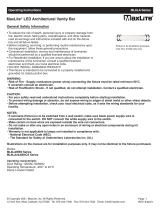
Modèle:
Série MSF
© Droits d’auteur 2022. MaxLite, Inc. Tous droits réservés.
12 York Ave, West Caldwell, NJ 07006 Tél: 800-555-5629 Fax: 973-244-7333 Email: info@maxlite.com
Page: 1
RÉV: 03/15/22
Consignes générales de sécurité
Mode d’emploi Série MSF
Projecteurs à profil mince MaxLite DEL (15W-140W)
®
L’image est pour des fins d’illustration
seulement. Votre modèle peut être
différent.
Schéma général de câblage
PRÉCAUTION: Débranchez l’alimentation électrique au fusible ou au disjoncteur avant de
connecter le luminaire à la source d’alimentation.
Câblage pour variateur 0-10V:
1.) Connectez le fil noir du luminaire au fil d’alimentation LIGNE CHARGÉE.
2.) Connectez le fil blanc du luminaire au fil d’alimentation NEUTRE.
3.) Connectez le fil vert du luminaire au fil de terre de l’alimentation.
4.) Connectez le fil violet du luminaire au fil VAR (V+).
5.) Connectez le fil rose du luminaire au fil VAR (V-).
Mode d’emploi Série MSF
Projecteurs à profil mince MaxLite DEL (15W-140W)
®
© Droits d’auteur 2022. MaxLite, Inc. Tous droits réservés.
12 York Ave, West Caldwell, NJ 07006 Tél: 800-555-5629 Fax: 973-244-7333 Email: info@maxlite.com
Page: 2
RÉV: 03/15/22
1.) Enlevez le luminaire de l’emballage.
2.) Connectez les fils d’entrée CA du support de montage aux fils d’alimentation électrique (Fig. 1).
Support articulé ½ NPT (seulement pour 15W, 25W, 60W)
Luminaires et lampions Support articulé 1/2
Violet: VAR+
Rose: VAR-
Vis d’angle
Noir/Marron: ACL
Vert/Jaune
Blanc/Bleu: ACN
3.) Desserrez la vis centrale du support de montage et ajustez l’angle désiré.
Serrez la vis (Fig. 2).
4.) Insérez le raccord fileté de 12,5 mm (½”) dans la surface de montage (poteau, boîtier de jonction, etc.).
Assurez-vous qu’il est fixé en le serrant sur la surface de montage ou en utilisant l’écrou fourni (Fig. 3).
poteau
Mode d’emploi Série MSF
Projecteurs à profil mince MaxLite DEL (15W-140W)
®
© Droits d’auteur 2022. MaxLite, Inc. Tous droits réservés.
12 York Ave, West Caldwell, NJ 07006 Tél: 800-555-5629 Fax: 973-244-7333 Email: info@maxlite.com
Page: 3
RÉV: 03/15/22
1.) Enlevez le luminaire de l’emballage.
2.) S’il existe un support de montage autre que le support en U (c’est-à-dire un support articulé), enlevez-le du
luminaire (Fig. 4).
Support en U (tous les modèles)
3.) Attachez le support en U au luminaire avec les deux (2) boulons fournis (Fig. 5).
4.) Percez deux (2) trous dans la surface de montage en utilisant le support en U comme modèle (Fig. 6).
5.) Insérez les boulons d’expansion (boulons d’ancrage) dans les trous percés à l’étape 4 (Fig. 7).
Boulon d’expansion
L
6.) Attachez le support en U à la surface, desserrez les boulons des deux côtés du support en U et ajustez
l’angle désiré du luminaire. Fixez le luminaire dans cette position en serrant les boulons des deux côtés
du support en U (Fig. 8).
7.) Connectez les fils d’entrée CA du support de montage aux fils d’alimentation électrique (Fig. 9).
Luminaires et lampions
Noir/Marron: ACL
Vert/Jaune
Blanc/Bleu: ACN
Support articulé 1/2
Violet: VAR+
Rose: VAR-
Mode d’emploi Série MSF
Projecteurs à profil mince MaxLite DEL (15W-140W)
®
© Droits d’auteur 2022. MaxLite, Inc. Tous droits réservés.
12 York Ave, West Caldwell, NJ 07006 Tél: 800-555-5629 Fax: 973-244-7333 Email: info@maxlite.com
Page: 4
RÉV: 03/15/22
1.) Enlevez le luminaire de l’emballage.
2.) Connectez les fils d’entrée CA du support de montage aux fils d’alimentation électrique (Fig. 10). Posez les
fils dans le poteau et mettez le raccord sur le poteau. Fixez le raccord sur le poteau en serrant les boulons
de verrouillage.
3.) Desserrez la vis centrale du support de montage et ajustez l’angle désiré. Serrez la vis (Fig. 11).
Montage à raccord lisse (seulement pour 105W, 140W)
Luminaires et lampions
Vis d’angle
Noir/Marron: ACL
Vert/Jaune
Blanc/Bleu: ACN
Support articulé 1/2
Violet: VAR+
Rose: VAR-
1.) Enlevez les bouchons d’entrée de câble en métal et en plastique de la partie supérieure du luminaire (Fig. 12)
Installation et fonctionnement – Température de la couleur (TCP) / Réglage de la puissance & Contrôleur PC
2.) Réglez la valeur TCP de la température de couleur désirée, la puissance du contrôleur (seulement pour
les modèles WCS), et mettez le contrôleur de la photocellule en position activée ou désactivée (Fig. 13).
3.) Réinstallez les bouchons d’entrée de câble, en vous assurant qu’ils sont étanches afin de prévenir l’accès
de l’eau. Le bouchon en plastique transparent sera utilisé pour l’orifice du contrôleur de la photocellule (Fig. 14).
Mode d’emploi Série MSF
Projecteurs à profil mince MaxLite DEL (15W-140W)
®
© Droits d’auteur 2022. MaxLite, Inc. Tous droits réservés.
12 York Ave, West Caldwell, NJ 07006 Tél: 800-555-5629 Fax: 973-244-7333 Email: info@maxlite.com
Page: 5
RÉV: 03/15/22
Cellule photoélectrique
et contrôleur de puissance
Contrôleur de couleur
5K
4K
3K
H
M
L
Mode d’emploi Série MSF
Projecteurs à profil mince MaxLite DEL (15W-140W)
®
© Droits d’auteur 2022. MaxLite, Inc. Tous droits réservés.
12 York Ave, West Caldwell, NJ 07006 Tél: 800-555-5629 Fax: 973-244-7333 Email: info@maxlite.com
Page: 6
RÉV: 03/15/22
MaxLite Inc. garantit ses produits pour une période minimale de CINQ (5) ans à partir de la date d’installation ou
90 jours après la date de l’achat de MaxLite ou son distributeur / revendeur autorisé (la « Période de Garantie »),
comme suit: Si un Produit ne fonctionne pas correctement pendant la Période de Garantie suite à des défauts de
matériaux ou de fabrication, MaxLite va, à sa discrétion, réparer ou remplacer le produit avec un modèle identique
ou similaire.
Veuillez consulter le site web de Maxlite (sur http://maxlite.com/resources/warranties) pour les détails de couverture
et la version complète des termes et conditions de garantie. Veuillez noter qu'il N'EST PAS obligatoire d'enregistrer
la garantie afin d'initier une réclamation de garantie, sauf si une garantie de dix ans a été achetée séparément, ou
si applicable et / ou achetée séparément, votre garantie couvre le coût de la main-d'oeuvre de remplacement.
Limitation de Responsabilité
CETTE GARANTIE EST EXCLUSIVE ET REPRÉSENTE LE SEUL RECOURS POUR TOUTES LES
RÉCLAMATIONS, QU'ELLES SOIENT CONTRACTUELLES, CIVILES OU AUTREMENT DÉCOULANT DE LA
DÉFAILLANCE DU PRODUIT ET REMPLACE TOUTES LES AUTRES GARANTIES, EXPRESSES OU IMPLICITES,
Y COMPRIS TOUTES LES GARANTIES DE COMMERCIALISATION OU L'ADÉQUATION À UN USAGE
PARTICULIER DONT LES GARANTIES SONT EXPRESSÉMENT DÉCLINÉES DANS LA MESURE PERMISE PAR
LA LOI ET, EN TOUT CAS, SONT LIMITÉES À LA PÉRIODE DE GARANTIE SPÉCIFIÉE CI-DESSUS. LA
RESPONSABILITÉ DE MAXLITE EST LIMITÉE AUX TERMES DE LA GARANTIE EXPRESSE DÉFINIE DANS LES
PRÉSENTES. MAXLITE NE SERA EN AUCUN CAS RESPONSABLE DES DOMMAGES PARTICULIERS,
ACCESSOIRES OU CONSÉCUTIFS, Y COMPRIS, SANS S'Y LIMITER, LES DOMMAGES RÉSULTANT DE LA
PERTE D'UTILISATION, DES BÉNÉFICES, DES AFFAIRES OU DE LA BONNE VOLONTÉ, DES FRAIS DE MAIN
D'OEUVRE, DES FRAIS DE DÉMÉNAGEMENT OU D'INSTALLATION, QUE MAXLITE SOIT AVERTI OU NON DE
CETTE POSSIBILITÉ. EN AUCUN CAS LA RESPONSABILITÉ DE MAXLITE POUR UN PRODUIT DÉFECTUEUX
NE DÉPASSERA LE PRIX D'ACHAT DE CE PRODUIT (SAUF LA COUVERTURE DES COÛTS DE LA MAIN
D’OEUVRE SI ELLE EST OFFERTE SPÉCIFIQUEMENT PAR MAXLITE). LES SERVICES DE GARANTIE FOURNIS
EN VERTU DE CES TERMES ET CONDITIONS NE GARANTISSENT PAS LE FONCTIONNEMENT
ININTERROMPU DES PRODUITS; MAXLITE NE SERA PAS RESPONSABLE DES DOMMAGES CAUSÉS PAR
TOUT RETARD IMPLIQUANT LA RÉPARATION SOUS GARANTIE.
Cette garantie vous donne des droits légaux spécifiques et vous pouvez également avoir d'autres droits qui peuvent
varier d'un État à l'autre. Puisque certains États ou juridictions n'autorisent pas l'exclusion ou la limitation de
responsabilité pour les dommages indirects ou accessoires, une telle limitation peut ne pas s'appliquer à vous.
Informations de garantie
  • Page 1 1
  • Page 2 2
  • Page 3 3
  • Page 4 4
  • Page 5 5
  • Page 6 6
  • Page 7 7
  • Page 8 8
  • Page 9 9
  • Page 10 10
  • Page 11 11
  • Page 12 12

LED Lighting MSF Series User manual

Type
User manual

LED Lighting MSF Series fixtures are designed for both commercial and residential use, providing energy-efficient lighting solutions for various applications. With a range of wattages from 15W to 140W, these slim flood fixtures offer adjustable color temperature and, for select models, wattage adjustment. Installation options include a ½ NPT knuckle mount, yoke mount, or slipfitter mount, allowing for flexible placement. The fixtures are suitable for use in wet locations and feature built-in surge protection for added safety.

Ask a question and I''ll find the answer in the document

Finding information in a document is now easier with AI

in other languages