MaxLite LSU4U23WCSCR User manual

Type
User manual

MaxLite LSU4U23WCSCR is a versatile lighting fixture with adjustable wattage and color temperature, making it suitable for various applications. It features three color temperatures (3500K, 4000K, and 5000K) and three wattage settings, allowing you to customize the lighting to your preference. The fixture is also compatible with 0-10V dimming, providing precise light control. Additionally, it has an optional CEA-RDW adapter for dimming via a remote control. The LSU4U23WCSCR is suitable for both indoor and outdoor use, with a sturdy construction that can withstand harsh conditions.

MaxLite LSU4U23WCSCR is a versatile lighting fixture with adjustable wattage and color temperature, making it suitable for various applications. It features three color temperatures (3500K, 4000K, and 5000K) and three wattage settings, allowing you to customize the lighting to your preference. The fixture is also compatible with 0-10V dimming, providing precise light control. Additionally, it has an optional CEA-RDW adapter for dimming via a remote control. The LSU4U23WCSCR is suitable for both indoor and outdoor use, with a sturdy construction that can withstand harsh conditions.

Operating Instructions LSU Series
MaxLite Utility Wrap - LSU Series
®
General Safety Information
To reduce the risk of death, personal injury or property damage from fire,
electric shock, falling parts, cuts/abrasions, and other hazards read all
warnings and instructions included with and on the fixture box and all
fixture labels.
• Before installing, servicing, or performing routine maintenance upon
this equipment, follow these general precautions.
• Commercial installation, service and maintenance of luminaires
should be performed by a qualified licensed electrician.
• For Residential installation: If you are unsure about the installation or
maintenance of the luminaires, consult a qualified licensed electrician
and check your local electrical code.
To prevent wiring damage or abrasion, do not expose wiring to edges of sheet
metal or other sharp objects.
• Do not make or alter any open holes in an enclosure of wiring or electrical
components during kit installation.
• DO NOT INSTALL DAMAGED PRODUCT!
• Suitable for Dry or Damp location
WARNING:
RISK OF ELECTRICAL SHOCK
• Turn off electrical power at fuse or circuit breaker box before wiring fixture
to the power supply.
• Turn off the power when you perform any maintenance.
• Verify that supply voltage is correct by comparing it with the luminaire label
information.
• Make all electrical and grounded connections in accordance with the National Electrical
Code and any applicable local code requirements.
All wiring connections should be capped with UL approved wire connectors.
CAUTION:
RISK OF INJURY
• Wear gloves and safety glasses at all times when removing luminaire from carton, installing,
servicing or performing maintenance.
Avoid direct eye exposure to the light source while it is on.
Account for small parts and destroy packing material, as these may be hazardous to children.
CAUTION:
RISK OF FIRE
• Keep combustible and other materials that can burn away from luminaire and lamp/lens.
NOTE: Green ground screw provided in proper location.
Do not relocate.
NOTE: Minimum 90° supply conductors.
NOTE: Specifications and dimensions subject to change without
notice.
NOTE: Suitable for Dry or Damp location.
Models:
This instruction manual applies to the LSU Series
Picture is for illustration purposes
only. Your model may vary.
© Copyright 2022 MaxLite, Inc. All Rights Reserved.
12 York Ave, West Caldwell, NJ 07006 Tel: 800-555-5629 Fax: 973-244-7333 Email: info@maxlite.com
Page: 1
REV: 03/30/22
Included in the box:
• LSU Utility Wrap Fixture
• Instructions
Setting Wattage & Color Temperature
Note: Applicable to models ending in WCS only. Models are set to lowest wattage and 4000K.
L
M
H
3500K
4000K
5000K
Color settings:
Left, stands for 3500K;
Middle, stands for 4000K;
Right, stands for 5000K;
Wattage settings:
Left, stands for Low;
Middle, stands for Medium;
Right, stands for High;
Adjust the color temperature and lumen output using the two DIP switches. Each DIP switch has 3 options (left,
middle and right), corresponding to 3 color temperatures and wattages. Use these switches to set desired color
temperature and lumen output combination.
Factory Settings: 4000K, lowest wattage based on fixture.
1. DIP switches are located on the side of fixture.
2. Select a wattage and color temperature by sliding switch left or right respectively to the desired value.
Wattage Switch
CCT Switch
Operating Instructions LSU Series
MaxLite Utility Wrap - LSU Series
®
© Copyright 2022 MaxLite, Inc. All Rights Reserved.
12 York Ave, West Caldwell, NJ 07006 Tel: 800-555-5629 Fax: 973-244-7333 Email: info@maxlite.com
Page: 2
REV: 03/30/22
General Wiring Diagram
CAUTION: Turn off electrical power at fuse
or circuit breaker box before wiring fixture to
the power supply.
Input Rating: 120-277V 50/60 Hz
Black = Line
White = Neutral
Green = Ground
TO SOURCE
120V-277V
GREEN (GROUND)
BLACK (LINE)
WHITE (NEUTRAL)
REDBLUEV-
BROWN
PURPLE PINK
LED DRIVER
+---+
(LEAD WIRES TO LED LOAD)(DIMMING WIRE TO 0-10V 
IEC COMPLIANT CONTROL)
Installation Instructions
V+
YELLOW
+
Anchors
Mounting screws
1. Remove product from packaging. 2. Remove lens by pulling from one side
of the fixture and hinge on the other.
3. Remove driver cover. 4. Use the luminaire as a template by placing
it on the junction box and penciling in the
ceiling the four holes positions. Put the
luminaire aside and drill the two holes. Insert
an anchoring bolt (not included) into each hole.
5. Screw the four mounting screws into
each anchoring bolt,then connect the
AC wires.
6. Install driver cover,then install lens on one
side of the fixture and rotate to engage the
opposite side.The installation is completed.
Operating Instructions LSU Series
MaxLite Utility Wrap - LSU Series
®
© Copyright 2022 MaxLite, Inc. All Rights Reserved.
12 York Ave, West Caldwell, NJ 07006 Tel: 800-555-5629 Fax: 973-244-7333 Email: info@maxlite.com
Page: 3
REV: 03/30/22
Emergency Battery Back-up Model Install Instructions (Additional Accessory)
Split Emergency Battery Back-up:
LED
Driver
Emergency
Driver
Battery Test Switch
BATTERY TBSW
EMERGENCY
LED DRIVER
SWITCH
COMMON
HOT
WHT
BLK
WHT/BLK
WHT
BLK
GRAY/PINK
WHT
BLK
RED
RED
BLUE
CCT SW
WW
CW
Operating Instructions LSU Series
MaxLite Utility Wrap - LSU Series
®
© Copyright 2022 MaxLite, Inc. All Rights Reserved.
12 York Ave, West Caldwell, NJ 07006 Tel: 800-555-5629 Fax: 973-244-7333 Email: info@maxlite.com
LED DRIVER
Black
White
+
-
+
-
+
-
Yellow
Brown
Purple
Gray/Pink
Red
Blue
Yellow
Purple
Gray/Pink
+
-
+
L
N
EMERGENCY LED DRIVER
White
Black
Black/White Gray/Pink
White
Red
Black
Brown
Purple
Brown
Purple
TEST SWITCH
BATTERY
LED
Gray/Pink +
-
White
SENSOR
Emergency Battery Back-up Wiring For Sensor Models
c-Max
Sensor
LED
Driver
ANT-9
Sensor
CCT
Switch
Test
Switch Emergency
Driver
Battery
2ft:4ft:
Page: 4
REV: 03/30/22
c-Max™ node Installation Instructions (Applicable only on CR models)
1. Remove the lens to access the USB-C receptacle. (see Fig. 1).
2. Remove the silicone plug from the USB-C receptacle (see Fig. 2).
3. Plug the c-Max™ node into the USB-C receptacle via the USB connection (see Fig. 3).
4. Secure the c-Max™ node in place by fastening the included M3 button head screw with a Hex (Allen) key
(not included). Once the screw is secured, cover it with the included silicone cap (see Fig. 4 - drawing for
illustration only, actual screw may look different.)
Note: In motion sensor models, the USB-C receptacle if present would no longer be functional.
Note: For tightening the hex screw, please use a M2 allen key or equivalent.
Fig. 1
Fig. 2 Fig. 3
Fig. 3
Operating Instructions LSU Series
MaxLite Utility Wrap - LSU Series
®
© Copyright 2022 MaxLite, Inc. All Rights Reserved.
12 York Ave, West Caldwell, NJ 07006 Tel: 800-555-5629 Fax: 973-244-7333 Email: info@maxlite.com
Page: 5
REV: 03/30/22
Controls Ready (CR) Model Standard Wiring Diagram
Risk of fire or electric shock, installation requires knowledge of the lighting luminaires electrical
systems. If not qualified, do not attempt installation and contact a qualified electrician.
Black
White
Green
L
N
GND
AC120V-277V
L
N
GND
LED+
LED-
DIM+
DIM-
YELLOW
12V AUX
Red (Driver +)
Black (Driver -)
Purple
Gray/Pink
USB-C
Receptacle
Controls Ready (CR) Model Daisy-Chained Wiring Diagram
LED’s
• Remove Dim+ and Dim- from the USB-C receptacle from the Child-Fixtures to connect to the Dim+, Dim-
of the parent fixture.
The USB-C receptacle will no longer function on the Child-Fixtures.
• No more then 8 fixtures total when daisy chaining.
AC120V-277V
LED+
LED-
DIM-
USB-C
Receptacle
LED’s
LED’s
12V AUX
YELLOW
Black
White
Green
L
N
GND
LN
GND
LED+
LED-
DIM+
DIM-
YELLOW
12V AUX
Red (Driver +)
Black (Driver -)
Purple
Gray/Pink
Red (Driver +)
Black (Driver -)
Purple
Gray/Pink
Operating Instructions LSU Series
MaxLite Utility Wrap - LSU Series
®
© Copyright 2022 MaxLite, Inc. All Rights Reserved.
12 York Ave, West Caldwell, NJ 07006 Tel: 800-555-5629 Fax: 973-244-7333 Email: info@maxlite.com
Page: 6
REV: 03/30/22
Operating Instructions LSU Series
MaxLite Utility Wrap - LSU Series
®
© Copyright 2022 MaxLite, Inc. All Rights Reserved.
12 York Ave, West Caldwell, NJ 07006 Tel: 800-555-5629 Fax: 973-244-7333 Email: info@maxlite.com
Page: 7
REV: 03/30/22
CEA-RDW Adapter Installation Instructions
1. Remove the lens and the LED board to expose the LED driver. Knock away the knockout hole on one of
the end-caps.
2. Run the wires from the adapter through the knock out hole of the fixture and attach the adapter using
the locking nut. Ensure that the adapter is facing downwards after the fixture is installed.
3. Connect the wires according to the wiring diagram. Re-attach the LED board and the lens to the fixture.
General Wiring Diagram
0-10V DIM LED Driver
Purple
Gray/Pink
Yellow
Vaux+Vaux-
DIM-
(Gray/Pink)
DIM+ (Purple)
LED- (Black)
LED+ (Red)
L
N
GND
Fixture
Lock Nut
Adapter
CAUTION: Turn off electrical power at fuse or circuit breaker box before wiring fixture to the power supply.
10-Year standard warranty with labor allowance*
(see terms at www.maxlite.com/warranties)
*Warranty Limitations: Product must be rated for application per the Product Data Sheet (PDS); operated 16 hrs;
in ambient temperatures -4°F to 77°F.
*Up to $25/unit; registration required. Additional coverage may be available for purchase; contact MaxLite.
*Excludes EM/MS versions; component warranty applies.
*If ambient temperatures fall outside the -4°F to 77°F range; product is warrantied for 5 years according to the
operating temperature range specified on the PDS.
Limitation of Liability
THE FOREGOING WARRANTY IS EXCLUSIVE, AND IS THE SOLE REMEDY FOR ANY AND ALL CLAIMS,
WHETHER IN CONTRACT, IN TORT OR OTHERWISE ARISING FROM THE FAILURE OF PRODUCT AND IS IN
LIEU OF ALL OTHER WARRANTIES, EXPRESS OR IMPLIED, INCLUDING ALL WARRANTIES OF
MERCHANTABILITY OR FITNESS FOR A PARTICULAR PURPOSE, WHICH WARRANTIES ARE HEREBY
EXPRESSLY DISCLAIMED TO THE EXTENT PERMITTED BY LAW AND, IN ANY EVENT, SHALL BE LIMITED TO
THE WARRANTY PERIOD SPECIFIED ABOVE. THE LIABILITY OF MAXLITE SHALL BE LIMITED TO THE TERMS
OF THE EXPRESS WARRANTY SET FORTH HEREIN. IN NO EVENT WILL MAXLITE BE LIABLE FOR ANY
SPECIAL, INCIDENTAL OR CONSEQUENTIAL DAMAGES INCLUDING, WITHOUT LIMITATION, DAMAGES
RESULTING FROM LOSS OF USE, PROFITS, BUSINESS OR GOODWILL, LABOR COSTS, REMOVAL OR
INSTALLATION COSTS, DECREASE IN THE LIGHT OUTPUT OF THE LAMP, AND/OR DETERIORATION IN THE
LAMP’S PERFORMANCE, WHETHER OR NOT MAXLITE HAS BEEN ADVISED OF THE POSSIBILITY THEREOF.
UNDER NO CIRCUMSTANCES SHALL MAXLITE’S ENTIRE LIABILITY FOR A DEFECTIVE PRODUCT EXCEED
THE PURCHASE PRICE OF THAT PRODUCT. WARRANTY SERVICES PROVIDED UNDER THESE TERMS AND
CONDITIONS DO NOT ENSURE THE UNINTERRUPTED OPERATION OF PRODUCTS; MAXLITE SHALL NOT BE
LIABLE FOR DAMAGES CAUSED BY ANY DELAYS INVOLVING WARRANTY SERVICE.
This Limited Warranty gives you specific legal rights and you may also have other rights that may vary from state to
state. Because some states or jurisdictions do not allow the exclusion or limitation of liability for consequential or
incidental damages, this limitation may not apply to you.
Warranty Information
Operating Instructions LSU Series
MaxLite Utility Wrap - LSU Series
®
© Copyright 2022 MaxLite, Inc. All Rights Reserved.
12 York Ave, West Caldwell, NJ 07006 Tel: 800-555-5629 Fax: 973-244-7333 Email: info@maxlite.com
Page: 8
REV: 03/30/22
Mode d’emploi Série LSU
Luminaire enveloppant utilitaire DEL MaxLite - Série LSU
®
Consignes générales de sécurité
• Pour réduire les risques de décès, de blessure ou de dommages matériels dus
aux incendies, aux décharges électriques, aux chutes de pièces, aux
coupures/abrasions et autres dangers, lisez tous les avertissements et consignes
inclus et figurant sur le boîtier et toutes les étiquettes du luminaire.
• Avant de procéder à l’installation, à la réparation ou à l’entretien courant de cet
appareil, suivez les présentes précautions générales.
• L’installation, la réparation et l’entretien des luminaires dans un bâtiment
commercial doivent être effectués par un électricien qualifié et agréé.
• Installation dans un bâtiment résidentiel : En cas de doutes sur l’installation ou
sur l’entretien des luminaires, faites appel à un électricien agréé qualifié et
consultez le code électrique applicable à votre région.
• Pour éviter tout dommage ou abrasion du câblage, n’exposez pas le câblage
aux bords de la tôle ou à d’autres objets pointus.
• Ne pratiquez pas une ouverture de trou ou ne modifiez pas les trous ouverts
dans un boîtier de câblage ou de composants électriques pendant l’installation de la trousse.
• N’INSTALLEZ PAS UN PRODUIT ENDOMMAGÉ!
• Adapté aux emplacements secs ou humides.
AVERTISSEMENT: RISQUE D’ÉLECTROCUTION
• Coupez l’alimentation électrique au niveau du fusible ou du disjoncteur avant de brancher le
luminaire à l’alimentation électrique.
• Coupez l’alimentation électrique lorsque vous effectuez des travaux d’entretien.
• Vérifiez que la tension d’alimentation est correcte en la comparant avec les renseignements
figurant sur l’étiquette du luminaire.
• Effectuez tous les raccordements électriques et les mises à la terre conformément au code
national de l’électricité et à toutes les exigences des codes en vigueur dans la région.
• Tous les branchements de câbles doivent être recouverts de connecteurs de fils
homologués UL.
ATTENTION: RISQUE DE BLESSURE
• Portez des gants et des lunettes de sécurité à tout moment lorsque vous retirez un luminaire
du carton, lorsque vous procédez à son installation , sa réparation et son entretien.
• Évitez toute exposition directe des yeux à la source de lumière du luminaire lorsque celui-ci
est allumé.
• Tenez compte de petites pièces et détruisez les matériaux d’emballage, car ils peuvent
être dangereux pour les enfants.
ATTENTION: RISQUE D’INCENDIE
• Éloignez du luminaire et de la lampe/lentille tout matériau combustible et autres qui peuvent brûler.
REMARQUE: La vis de mise à la terre verte est fournie à l’emplacement
approprié. Ne changez pas d’emplacement.
REMARQUE: Conducteurs d’alimentation à 90° minimum.
REMARQUE: Les spécifications et dimensions peuvent être
modifiées sans préavis.
REMARQUE: Adapté aux emplacements secs ou humides.
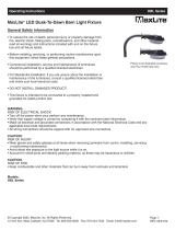
Modèles:
Ce mode d’emploi s’applique à la série LSU
La photo n’est fournie qu’à titre
d’illustration uniquement, votre
modèle peut être différent
© Copyright 2022 MaxLite, Inc. Tous droits réservés.
12 York Ave, West Caldwell, NJ 07006 Tél: 800-555-5629 Télécopie: 973-244-7333 Courriel: info@maxlite.com
Page: 1
REV: 3/30/22
Contenu de la boite d’emballage:
• Le luminaire enveloppant utilitaire
DEL, série LSU
• Le mode d’emploi
Réglage de la puissance et de la température de couleur
Remarque: Applicable aux modèles se terminant par WCS uniquement. Les modèles sont réglés
sur la puis-sance la plus faible et à la température de couleur de 4000K.
L
M
H
3500K
4000K
5000K
Paramètres de couleur:
Gauche: 3500K;
Milieu: 4000K;
Droit: 5000K;
Réglages de la puissance:
Gauche: Faible;
Milieu: Moyenne;
Droit: Élevée;
Réglez la température de couleur et la luminosité à l’aide des deux commutateurs DIP. Chaque commutateur DIP
comporte 3 options (gauche, milieu et droite), correspondant à 3 températures de couleur et puissances. Utilisez ces
commutateurs pour régler la combinaison de température de couleur et de luminosité souhaitée.
Réglages d’usine: 4000K, puissance la plus faible en fonction du luminaire.
1. Les commutateurs DIP se trouvent sur le côté du luminaire.
2. Sélectionnez une puissance et une température de couleur en faisant glisser le commutateur vers la gauche ou
vers la droite, respectivement, jusqu’à la valeur souhaitée.
Interrupteur de puissance
Interrupteur CCT
Mode d’emploi Série LSU
Luminaire enveloppant utilitaire DEL MaxLite - Série LSU
®
© Copyright 2022 MaxLite, Inc. Tous droits réservés.
12 York Ave, West Caldwell, NJ 07006 Tél: 800-555-5629 Télécopie: 973-244-7333 Courriel: info@maxlite.com
Page: 2
REV: 3/30/22
Schéma général de câblage
ATTENTION: Coupez l’alimentation élec-trique
au niveau du fusible ou du disjoncteur
avant de brancher le luminaire à
l’alimentation électrique.
Tension d’entrée nominale: 120 à 277 V 50/60 Hz
Noir = Phase
Blanc = Neutre
Vert = Terre
À LA SOURCE
120V à 277V
VERT (TERRE)
NOIR (PHASE)
BLANC (NEUTRE)
ROUGEBLEUV-
MARRON
VIOLET
ROSE
CIRCUIT DE
COMMANDE à DEL
+---+
(FILS CONDUCTEURS VERS
LA CHARGE D’ÉCLAIRAGE
DEL)
(FIL DE GRADATEUR DIRIGÉ VERS UNE COMMANDE
D’ÉCLAIRAGE 0-10 V CON-FORME À LA NORME CEI)
Consignes d’installation
V+
JAUNE
+
Anchors
Mounting screws
1. Retirez le produit de son
emballage. 2. Retirez la lentille en tirant d’un côté du
luminaire et de la charnière de l’autre.
3. Enlevez le couvercle du circuit de
commande. 4. Utilisez le luminaire comme gabarit en le plaçant
sur le boîtier de jonction et en marquant au crayon les
quatre positions des trous sur le plafond. Mettez le
luminaire de côté et percez les deux trous. Insérez un
boulon d’ancrage (non inclus) dans chaque trou.
5. Serrez les quatre vis de fixation dans
chaque boulon d’ancrage, puis
connectez les fils d’alimentation C.A.
6. Installez le couvercle du circuit de commande, puis
installez la lentille sur un côté du luminaire et faites-la
tourner pour enclencher le côté opposé. L’installation
est terminée.
Mode d’emploi Série LSU
Luminaire enveloppant utilitaire DEL MaxLite - Série LSU
®
© Copyright 2022 MaxLite, Inc. Tous droits réservés.
12 York Ave, West Caldwell, NJ 07006 Tél: 800-555-5629 Télécopie: 973-244-7333 Courriel: info@maxlite.com
Page: 3
REV: 3/30/22
Consignes d’installation du modèle de luminaire d’urgence avec pile de secours
(accessoire supplémentaire)
PILE TBSW
SECOURS
CIRCUIT DE
COMMANDE À DEL
COMMUTATEUR
MASSE
PHASE
Blanc
Noir
Blanc/Noir
Blanc
Noir
Gris/Rose
Blanc
Noir
Rouge
Rouge
Bleu
INTERRUPTEUR
CCT
WW
CW
Câblage du luminaire d’urgence avec pile de secours pour les modèles à capteurs
Mode d’emploi Série LSU
Luminaire enveloppant utilitaire DEL MaxLite - Série LSU
®
© Copyright 2022 MaxLite, Inc. Tous droits réservés.
12 York Ave, West Caldwell, NJ 07006 Tél: 800-555-5629 Télécopie: 973-244-7333 Courriel: info@maxlite.com
Page: 4
REV: 3/30/22
Circuit de
commande d’urgence
Pile
Circuit de
commande à DEL
Commutateur de test
c-Max
Capteur
Circuit de
commande à DEL
ANT-9
Capteur
CCT
Interrupteur
Commutateur
de test
Circuit de
commande d’urgence
Pile
2ft:4ft:
Luminaire de secours avec pile de secours à phase auxiliaire:
Consignes d’installation du nœud c-Max™ (Applicable uniquement aux modèles prêts
à l’emploi)
1. Retirez la lentille pour accéder à la prise USB-C. (voir Fig. 1).
2. Retirez la fiche en silicone de la prise USB-C (voir Fig. 2).
3. Branchez le nœud c-MaxMC dans la prise USB-C via la connexion USB (voir Fig. 3).
4. Fixez le nœud c-MaxMC en place en serrant la vis à tête ronde M3 fournie à l’aide d’une clé hexagonale
(Allen) (non fournie). Une fois la vis fixée, recouvrez-la avec le capuchon en silicone fourni
(voir Fig. 4 - le schéma n’est fourni qu’à titre d’illustration, la vis réelle peut avoir un aspect différent).
Remarque: Dans les modèles à capteur de mouvement, la prise USB-C, le cas échéant,
ne serait plus fonctionnelle.
Remarque: Pour serrer la vis hexagonale, veuillez utiliser une clé Allen M2 ou une clé équivalente.
Fig. 1
Fig. 2 Fig. 3
Fig. 3
Mode d’emploi Série LSU
Luminaire enveloppant utilitaire DEL MaxLite - Série LSU
®
© Copyright 2022 MaxLite, Inc. Tous droits réservés.
12 York Ave, West Caldwell, NJ 07006 Tél: 800-555-5629 Télécopie: 973-244-7333 Courriel: info@maxlite.com
Page: 5
REV: 3/30/22
Schéma de câblage standard du modèle prêt à l’emploi (CR)
Risque d’incendie ou de décharge électrique, l’installation nécessite une connaissance des systèmes
électriques des luminaires. Si vous n’êtes pas qualifié, n’essayez pas de procéder à l’installation et
faites appel à un électricien qualifié.
Noir
Blanc
Vert
L
N
TERRE
AC120V-277V
LN
TERRE DEL+
DEL -
DIM+
DIM-
JAUNE
AUX 12V
Rouge (Circuit de commande+)
Noir (Circuit de commande-)
Violet
Gris/Rose
USB-C
Prise
Schéma de câblage en série du modèle prêt à l’emploi (CR)
DEL
• Retirez les Dim+ et Dim- de la prise USB-C du luminaire enfant pour les raccorder au Dim+, Dim- du
luminaire parent.
• La prise USB-C ne fonctionnera plus sur les luminaires enfants.
• Pas plus de 8 luminaires au total en cas de connexion en série.
AC120V-277V
LED+
LED-
DIM-
USB-C
Prise
DEL
DEL
12V AUX
YELLOW
Noir
Blanc
Vert
L
N
TERRE
LN
DEL+
DEL-
DIM+
DIM-
JAUNE
AUX 12V
Rouge (Circuit de commande+)
Noir (Circuit de commande-)
Violet
Gris/Rose
Rouge (Circuit de
commande+)
Noir (Circuit de
commande-)
Violet
Gris/Rose
Mode d’emploi Série LSU
Luminaire enveloppant utilitaire DEL MaxLite - Série LSU
®
© Copyright 2022 MaxLite, Inc. Tous droits réservés.
12 York Ave, West Caldwell, NJ 07006 Tél: 800-555-5629 Télécopie: 973-244-7333 Courriel: info@maxlite.com
Page: 6
REV: 3/30/22
TERRE
Mode d’emploi Série LSU
Luminaire enveloppant utilitaire DEL MaxLite - Série LSU
®
© Copyright 2022 MaxLite, Inc. Tous droits réservés.
12 York Ave, West Caldwell, NJ 07006 Tél: 800-555-5629 Télécopie: 973-244-7333 Courriel: info@maxlite.com
Page: 7
REV: 3/30/22
Instructions d'installation de l'adaptateur CEA-RDW
1. Retirez la lentille et la carte LED pour exposer le pilote LED. Enfoncez le trou à défoncer sur l'un des
les embouts.
2. Faire passer les fils de l’adaptateur à travers le trou de passage de fils de 1,25mm (1/2”) du luminaire et
attacher les fils en utilisant l’écrou de blocage.
3. Brancher les fils conformément au schéma de câblage. Rattacher le couvercle du luminaire, le cas échéant.
Schéma général de câblage
0-10V Pilote LED VAR
Violet
Gris/Rose
Jaune
Vaux+Vaux-
VAR-
(Gris/Rose)
VAR+ (Violet)
LED- (Noir)
LED+ (Rouge)
L
N
TERRE
Luminaire
Écrou de blocage
Adaptateur
PRÉCAUTION: Débranchez l’alimentation électrique au fusible ou au disjoncteur avant de connecter
le luminaire à la source d’alimentation.
Garantie standard main-d’œuvre de 10 ans*.
(consultez les conditions à l’adresse www.maxlite.com/warranties)
* Limites de garantie : Le produit doit être conçu pour une utilisation selon la fiche technique du produit; £utilisé 16
heures; à des températures ambiantes de -4 °F à 77 °F.
* Jusqu’à 25 $ par unité ; inscription requise. Une couverture supplémentaire peut être disponible à l’achat ;
commu-niquez avec MaxLite.
* Exclut les versions EM/MS; la garantie des composants s’applique.
* Si les températures ambiantes se situent en dehors de la plage -4 °F à 77 °F; le produit est garanti pendant 5 ans
si utilisé conformément à la plage de température de fonctionnement spécifiée sur la fiche technique.
Limitation de la responsabilité
LA GARANTIE CI-DESSUS EST EXCLUSIVE ET CONSTITUE LE SEUL RECOURS POUR TOUTE RÉCLAMATION,
QU’ELLE SOIT CONTRACTUELLE, DÉLICTUELLE OU AUTRE, DÉCOULANT DE LA DÉFAILLANCE DU PRODUIT
ET REMPLACE TOUTES LES AUTRES GARANTIES, EXPRESSES OU IMPLICITES, Y COMPRIS TOUTES LES
GARANTIES DE QUALITÉ MARCHANDE OU D’ADÉQUATION À UN USAGE PARTICULIER, LESQUELLES
GARANTIES SONT PAR LES PRÉSENTES EXPRESSÉMENT REJETÉES DANS LA MESURE PERMISE PAR LA
LOI ET, EN TOUT ÉTAT DE CAUSE, SONT LIMITÉES À LA PÉRIODE DE GARANTIE SPÉCIFIÉE CI-DESSUS. LA
RESPONSABILITÉ DE MAXLITE SE LIMITE AUX CONDITIONS DE LA GARANTIE EXPRESSE ÉNONCÉE AUX
PRÉSENTES. MAXLITE NE PEUT, EN AUCUN CAS, ÊTRE TENUE RESPONSABLE DE DOMMAGES SPÉCIAUX,
ACCESSOIRES OU CONSÉCUTIFS, Y COMPRIS, SANS S’Y LIMITER, LES DOMMAGES RÉSULTANT D’UNE
PERTE D’UTILISATION, DE BÉNÉFICES, D’ACTIVITÉ OU DE CLIENTÈLE, DE COÛTS DE MAIN-D’ŒUVRE, DE
RETRAIT OU D’INSTALLATION, D’UNE DIMINUTION DU RENDEMENT LUMINEUX DU LUMINAIRE ET/OU D’UNE
DÉTÉRIORATION DES PERFORMANCES DE CELLE-CI, QUE MAXLITE AIT ÉTÉ OU NON INFORMÉ DE LA
POS-SIBILITÉ DE TELS DOMMAGES. EN AUCUN CAS, LE MONTANT TOTAL DE LA RÉCLAMATION POUR
PRODUIT DÉFECTUEUX DONT MAXLITE ASSUME L’ENTIÈRE RESPONSABILITÉ DE NE PEUT DÉPASSER LE
PRIX D’ACHAT DE CE PRODUIT. LES SERVICES DE GARANTIE FOURNIS DANS LE CADRE DES PRÉSENTES
CON-DITIONS GÉNÉRALES NE GARANTISSENT PAS LE FONCTIONNEMENT ININTERROMPU DES PRODUITS;
MAXLITE NE PEUT ÊTRE TENUE RESPONSABLE DES DOMMAGES CAUSÉS PAR TOUT RETARD IMPLIQUANT
UN SERVICE DE GARANTIE.
La présente garantie limitée vous accorde des droits légaux spécifiques et vous avez également la possibilité de
dis-poser d’autres droits qui peuvent varier d’un État à l’autre. Étant donné que certains États ou territoires
n’autorisent pas l’exclusion ou la limitation de responsabilité pour les dommages consécutifs ou accidentels, cette
limitation peut ne pas s’appliquer à votre cas.
Informations sur la garantie
Mode d’emploi Série LSU
Luminaire enveloppant utilitaire DEL MaxLite - Série LSU
®
© Copyright 2022 MaxLite, Inc. Tous droits réservés.
12 York Ave, West Caldwell, NJ 07006 Tél: 800-555-5629 Télécopie: 973-244-7333 Courriel: info@maxlite.com
Page: 8
REV: 3/30/22
  • Page 1 1
  • Page 2 2
  • Page 3 3
  • Page 4 4
  • Page 5 5
  • Page 6 6
  • Page 7 7
  • Page 8 8
  • Page 9 9
  • Page 10 10
  • Page 11 11
  • Page 12 12
  • Page 13 13
  • Page 14 14
  • Page 15 15
  • Page 16 16

MaxLite LSU4U23WCSCR User manual

Type
User manual

MaxLite LSU4U23WCSCR is a versatile lighting fixture with adjustable wattage and color temperature, making it suitable for various applications. It features three color temperatures (3500K, 4000K, and 5000K) and three wattage settings, allowing you to customize the lighting to your preference. The fixture is also compatible with 0-10V dimming, providing precise light control. Additionally, it has an optional CEA-RDW adapter for dimming via a remote control. The LSU4U23WCSCR is suitable for both indoor and outdoor use, with a sturdy construction that can withstand harsh conditions.

Ask a question and I''ll find the answer in the document

Finding information in a document is now easier with AI

in other languages