Page is loading ...

1 of 14
Acuity Brands | One Lithonia Way Conyers, GA 30012 Phone: 800.535.2465 https://nlight.acuitybrands.com/ © 2020-2021 Acuity Brands Lighting, Inc. All rights reserved. Rev. 05/28/2021
nLight® AIR
Design Guide
Please read this document prior to designing nLight AIR systems for either retrofit or
new construction.
Designs that do not adhere to these guidelines may have performance problems once in-
stalled and configured. Following the information in this guide will significantly increase the
likelihood of a trouble-free startup.

2 of 14
Acuity Brands | One Lithonia Way Conyers, GA 30012 Phone: 800.535.2465 https://nlight.acuitybrands.com/ © 2020-2021 Acuity Brands Lighting, Inc. All rights reserved. Rev. 05/28/2021
nLight AIR Design Guide
1-1 Wireless Communication Principles .............................................................................................................................. 3
1-2 nLight AIR Design Limitations ...................................................................................................................................... 3
2-1 Range Considerations: Outdoor Applications ............................................................................................................. 5
2-2 Range Considerations: Indoor Applications ................................................................................................................. 6
3-1 Adapter Mounting Notes ........................................................................................................................................... 10
4-1 General Operation and Power Requirements ............................................................................................................ 10
4-2 System Architecture: Stand-Alone Systems ................................................................................................................ 11
4-3 System Architecture: Networked Systems ................................................................................................................. 12
4-3 System Architecture: Networked Systems ................................................................................................................. 12
5-1 Frequently Asked Questions ...................................................................................................................................... 14
Table of Contents

3 of 14
Acuity Brands | One Lithonia Way Conyers, GA 30012 Phone: 800.535.2465 https://nlight.acuitybrands.com/ © 2020-2021 Acuity Brands Lighting, Inc. All rights reserved. Rev. 05/28/2021
nLight AIR Design Guide
nLight AIR equipment communicates in the 900MHz band (904 - 926 MHz). This frequency band allows for longer
communication distances in both open air and through obstructions.
However, each additional obstruction reduces the signal strength and overall communication distance.
Designs should include line-of-sight communication as a goal, followed by reflected signal, and lastly by
penetration through obstacles. This approach ensures the most reliable communication between devices.
1-2 Wireless Communication Principles
200 ft
Consider the example to the right. If trying to communicate
with all others in space by yelling, a voice will better propagate
through the space in some ways better than others. If standing
in a private office on the right-hand side, a voice may only
travel though a few walls before it is no longer strong enough
to be heard. However, it may be able to travel out into the
open office space and be heard in areas across the floor —
keeping in mind that sound can reflect and enter spaces not in
direct line-of-sight. These same principles are true with radio
frequency (hereafter referred to as “RF”.) All materials have
some finite impact on the signal strength of RF, much like they
do a voice.
The graphic to the right shows how distance and reflection
change the signal strength in an environment. Compared
to the signal strength of reflections, nLight AIR’s RF signal
strength over 200’ line-of-sight would be much stronger than
attempting to penetrate multiple walls.
Each additional obstruction will reduce the signal strength.
STAND-ALONE SYSTEMS
When designing a stand-alone nLight AIR system, one must design to the
following practices:
• No more than 128 devices per Group
• Design stand-alone spaces as Groups. A Group is a collection of
devices that occupy the same room or space and share the same
behaviors.
• Assumed range should not exceed more than three hops at budgetary
range through the interior of a building (inclusive of an initial
broadcast from a Group Monitor and two repeats using devices in the
space)
• Assumed range should not exceed more than four hops from a Group
Monitor using line of sight communication (inclusive of an initial
broadcast from a Group Monitor and three repeats using devices in the
space)
1-1 nLight AIR Design Limitations
NETWORKED SYSTEMS
When designing a networked nLight AIR system, one must design to the
following practices:
• No more than 255 nLight ECLYPSE devices per Site
• No more than 750 devices per nLight ECLYPSE
• No more than 20,000 devices per Site
• No more than 128 devices per Group
• One Site per instance of SensorView
• For maximum distance between networked devices, see Section 2
• Assumed range should not exceed more than three hops at budgetary
range through the interior of a building (inclusive of an initial
broadcast and two repeats using devices in the space)
• Assumed range should not exceed more than four hops between
devices using line-of-sight communication (inclusive of an initial
broadcast and three repeats using devices in the space)

4 of 14
Acuity Brands | One Lithonia Way Conyers, GA 30012 Phone: 800.535.2465 https://nlight.acuitybrands.com/ © 2020-2021 Acuity Brands Lighting, Inc. All rights reserved. Rev. 05/28/2021
nLight AIR Design Guide
When verifying repeater candidate viability, the following
should be considered at a minimum:
• Distance between a broadcaster and repeater candidates
should be less than the budgetary range recommended
for a space type.
• Distance between repeater candidates and a receiver
should be less than the budgetary range recommended
for a space type.
• Designers should confirm that no significant obstructions
exist between respective broadcaster, repeater candidates,
and receiver devices.
RECEIVER
REPEATER CANDIDATE
IN
OUT
n
NECYD NLTAIR
n
UP TO 1000'
UP TO 1000'
UP TO 1000'
UP TO 1000'
UP TO 1000'
UP TO 1000'
NECY MVOLT ENC
UP TO 1000'
BROADCASTER
Designs should not rely on autonomous bridging
when multiple repeater candidates are not available.
Autonomous bridging adds reliability to an nLight AIR design
by making use of devices in the space. As the quantity of
devices over a given distance lowers, the opportunity for a
reliable network self-forming or self-repairing is reduced.
SUPPORTED
NOT SUPPORTED
BROADCASTER
REPEATER CANDIDATE
1,000’ Initial Broadcast (Hop 1) Multiple candidates in
initial broadcast
Multiple candidates for
subsequent hops
1,000’ Repeat Broadcast (Hop 2)
BROADCASTER
1,000’ Initial Broadcast (Hop 1) Single candidate in
initial broadcast
Single candidate for
subsequent hops
1,000’ (Hop 3)
1,000’ Repeat Broadcast (Hop 2) 1,000’ (Hop 4)
Through nLight AIR autonomous bridging technology, wireless devices that are neither switch-type nor battery-
powered can be used as repeaters, enabling the ability to repeat messages to and from an nLight ECLYPSE™ or
Group Monitor without adding additional devices to the space.
Network messages that can be repeated include profiles,
settings updates made through SensorView, BACnet
commands and polling, firmware updates, and other network
communication.
Non-networked (standalone) messages that can be repeated
across groups of AIR devices include switch, occupancy
sensor, and photocell broadcasts. Broadcasts from battery
powered devices and switch devices must reach the group
monitor before they can be repeated. Non-battery/non-switch
broadcasts can be repeated to reach a Group Monitor and can
be repeated from the Group Monitor to the receiving device(s).
Devices that can act as repeaters through autonomous bridging
include the rPP, rES7, rIO, rCMS, rSDGR, rMSOD, rLSXR, rSBOR,
and rSBG.
Battery powered devices and switches cannot serve as repeater
candidates. Such devices include the rPODB, rPODL, and
rCMSB.
BROADCASTER
REPEATERRECEIVER

5 of 14
Acuity Brands | One Lithonia Way Conyers, GA 30012 Phone: 800.535.2465 https://nlight.acuitybrands.com/ © 2020-2021 Acuity Brands Lighting, Inc. All rights reserved. Rev. 05/28/2021
nLight AIR Design Guide
IN
OUT
n
NECYD NLTAIR
n
UP TO 1000'
UP TO 1000'
UP TO 1000'
UP TO 1000'
UP TO 1000'
UP TO 1000'
NECY MVOLT ENC
UP TO 1000'
IN
OUT
'0001 OT PU
UP TO 1000'
UP TO 1000'
UP TO 1000'
UP TO 1000'
Networked ABT* - Typical Parking Lot Standalone ABT* - Typical Parking Lot
*Red nLight AIR devices and fixtures are representative of repeater-enabled devices.
*Blue devices and fixtures are representative of Group Monitors
Typical Parking Lot or Building Exterior
Use 1,000’ radius (line-of-sight communication only) for budgetary purposes when all obstructions cannot be confirmed
and avoided or when signal strength has not been tested.
• Maximum budgetary range should consist of no more than an initial broadcast and three repeats using devices in the space.
• For networked systems, an nLight AIR Adapter (NECYD NLTAIR G2, hereafter referred to as “Adapter”) should be mounted outside on a wall or edge of a
roof. Mounting on the corner of walls allows for the widest field of view and maximum coverage outdoors — 270 degrees field of view.
o For site applications, it is desirable to get the clearest path and best unobstructed view from the Adapter to the fixtures being controlled.
o Radio frequency (RF) strength will weaken when penetrating exterior walls due to their typical construction. Mounting an Adapter on an exterior
wall--not a corner--will limit its range to 180 degrees of view.
o Tall fences or thick foliage can reduce signal strength.
o A higher mounting height is typically better for avoiding obstructions and increasing range. Lightning protection systems per UL96 may be
necessary depending on the Adapter mounting height.
o For protection from the elements, it is best to mount the Adapter
under an overhang or canopy while still retaining a clear field of
view from underneath the structure.
o When mounted outdoors, the Adapter must be mounted on an
IP66 rated, plastic enclosure with the gasket compressing against
the surface.
o In areas where regular snow accumulations are expected, it is
recommended to mount the Adapter on the bottom of a box to
avoid snow buildup around the Adapter.
• When designing with autonomous bridging and multiple repeater candidates do not appear at a given hop layer, additional devices should be added
to act as alternative repeater candidates — a requirement for a robust and reliable repeater network. An rSBOR or rPP20 CP (with exterior box by
others, as needed per the application environment) are versatile candidates that can be positioned to act as repeaters.
2-1 Range Considerations: Outdoor Applications

6 of 14
Acuity Brands | One Lithonia Way Conyers, GA 30012 Phone: 800.535.2465 https://nlight.acuitybrands.com/ © 2020-2021 Acuity Brands Lighting, Inc. All rights reserved. Rev. 05/28/2021
nLight AIR Design Guide
Typical Industrial / Warehouse Applications
Use 250’ radius for budgetary purposes when all obstructions cannot be confirmed and avoided, when
machinery and rack realignment is expected, or when signal strength has not been tested.
• Maximum budgetary range is 750’ radius (inclusive of repeats), unless a proper site survey has been performed to verify better performance.
• Typical construction is defined as large areas of open space with
minimum obstructions between the Adapter (or Group Monitor) and nLight AIR receiver.
• If networked, the Adapter should be mounted at the same height as other devices in the space (such as wireless sensors) to aid in avoiding
obstructions.
• For networked applications, a minimum of one Adapter should be used per floor.
• When designing with autonomous bridging and multiple repeater candidates do not appear at a given hop layer, additional devices should be
added to act as alternative repeater candidates — a requirement for a robust and reliable repeater network. An rSBOR, rPP20, or rCMS (connected to
an added or existing rPP20) is a versatile candidate that can be positioned to act as an alternative repeater.
2-2 Range Considerations: Indoor Applications
STORAGE RACKS
STORAGE RACKS
STORAGE RACKS
STORAGE RACKS
n
NECYD NLTAIR
n
UP TO 250' UP TO 250'
UP TO 250'
UP TO 250'
UP TO 250' UP TO 250'
UP TO 250'
UP TO 250'
STORAGE RACKS
STORAGE RACKS
STORAGE RACKS
UP TO 250' UP TO 250'
UP TO 250'
UP TO 250'
UP TO 250'
UP TO 250'
UP TO 250'
UP TO 250'
Networked ABT* - Typical Warehouse
Standalone ABT* - Typical Warehouse
*Red nLight AIR devices and fixtures are representative of repeater-enabled devices.
*Blue devices and fixtures are representative of Group Monitors

7 of 14
Acuity Brands | One Lithonia Way Conyers, GA 30012 Phone: 800.535.2465 https://nlight.acuitybrands.com/ © 2020-2021 Acuity Brands Lighting, Inc. All rights reserved. Rev. 05/28/2021
nLight AIR Design Guide
Typical Commercial Office Space
Use 150’ radius for budgetary purposes when all obstructions cannot be confirmed and avoided or signal strength has not
been tested.
• Maximum budgetary range is 450’ radius (inclusive of repeats), unless a proper site survey has been performed to verify better typical performance.
• Penetration of consecutive private office walls will diminish signal strength. Minimum, budgetary signal strength should be considered when
penetrating more than three dry walls of average construction.
• Open office and long hallways will improve range and are best choices for Adapter placements in networked applications.
• For networked applications, a minimum of one Adapter should be used per floor.
• When designing with autonomous bridging and multiple repeater candidates do not appear at a given hop layer, additional devices should be
added to act as alternative repeater candidates — a requirement for a robust and reliable repeater network. An rPP20 or rCMS (connected to an added
or existing rPP20) is a versatile candidate that can be positioned to act as an alternative repeater.
UP
DN
TELEPHONE
CLOSET
VESTIBULE
1605
1606
OPEN AREA
OPEN AREA
1604
LAB (SQA)
CONF.
ROOM
1603
n
NECYD NLTAIR
n
UP TO 600'
UP TO 600'
UP TO 600'
UP TO 600'
UP TO 600' UP TO 600'
UP TO 600'
UP TO 600'
UP
DN
TELEPHONE
CLOSET
VESTIBULE
1605
1606
OPEN AREA
OPEN AREA
1604
LAB (SQA)
CONF.
ROOM
1603
UP TO 600'
UP TO 600'
UP TO 600'
UP TO 600'
UP TO 600' UP TO 600'
UP TO 600'
UP TO 600'
Networked ABT* - Typical Office
Standalone ABT* - Typical Office
*Red nLight AIR devices and fixtures are representative of repeater-enabled devices.
*Blue devices and fixtures are representative of Group Monitors

8 of 14
Acuity Brands | One Lithonia Way Conyers, GA 30012 Phone: 800.535.2465 https://nlight.acuitybrands.com/ © 2020-2021 Acuity Brands Lighting, Inc. All rights reserved. Rev. 05/28/2021
nLight AIR Design Guide
ELEVATOR LOBBY
STAIRS
IN
OUT
DWN
UP
ELEC/MECH/DATA
n
NECYD NLTAIR
n
UP TO 100'
UP TO 100'
UP TO 100'
UP TO 100'
UP TO 100'
UP TO 100'
UP TO 100'
UP TO 100'
ELEVATOR LOBBY
STAIRS
IN
OUT
DWN
UP
ELEC/MECH/DATA
UP TO 100'
UP TO 100'
UP TO 100'
UP TO 100' UP TO 100'
UP TO 100'
UP TO 100'
UP TO 100'
Networked ABT* - Typical Parking Garage Standalone ABT* - Typical Parking Garage
Typical Commercial Parking Garage
Use 100’ radius for budgetary purposes when all obstructions cannot be confirmed and avoided or signal strength has not
been tested.
• Maximum budgetary range is 300’ radius (inclusive of repeats), unless a proper site survey has been performed to verify better typical performance.
• Reflections from floor to ceiling will be the primary means of communication in parking garages with vertical webs. The budgetary distance (100’)
should be used if construction type is unknown.
• For networked applications, a minimum of one Adapter should be used per floor, unless a proper site survey has been performed and confirms that
strong signal strength is available between the Adapter and multiple repeater candidates on another floor.
• When designing with autonomous bridging and multiple repeater candidates do not appear at a given hop layer, additional devices should be
added to act as alternative repeater candidates — a requirement for a robust and reliable repeater network. An rSBOR, rPP20 CP, or rCMS (connected
to an added or existing rPP20) is a versatile candidate that can be positioned to act as an alternative repeater.
*Red nLight AIR devices and fixtures are representative of repeater-enabled devices.
*Blue devices and fixtures are representative of Group Monitors

9 of 14
Acuity Brands | One Lithonia Way Conyers, GA 30012 Phone: 800.535.2465 https://nlight.acuitybrands.com/ © 2020-2021 Acuity Brands Lighting, Inc. All rights reserved. Rev. 05/28/2021
nLight AIR Design Guide
n
NECYD NLTAIR
n
UP TO 100'
UP TO 100'
UP TO 100'
UP TO 100'
UP TO 100'
UP TO 100'
UP TO 100'
UP TO 100'
UP TO 100'
UP TO 100'
UP TO 100'
UP TO 100'
UP TO 100'
UP TO 100'
UP TO 100'
UP TO 100'
Networked ABT* - Typical School Standalone ABT* - Typical School
Typical Municipal Buildings, Schools, and Hospitals
Use 100’ radius for budgetary purposes when all obstructions cannot be confirmed and avoided or when signal strength
has not been tested.
Networked ABT* - Typical Medical Center Standalone ABT* - Typical Medical Center
TENANT TENANT
PATIENT
RM
PATIENT
RM
EXAM
RM
EXAM
RM
EXAM
RM
EXAM
RM
EXAM
RM
EXAM
RM
EXAM
RM
LOBBY
/
RECEPTION
n
NECYD NLTAIR
UP TO 100'
UP TO 100'
UP TO 100'
UP TO 100'
RESTROOM
TENANT
SPACE
TENANT
SPACE
STORAGE
TENANT TENANT
PATIENT
RM
PATIENT
RM
EXAM
RM
EXAM
RM
EXAM
RM
EXAM
RM
EXAM
RM
EXAM
RM
EXAM
RM
LOBBY
/
RECEPTION
UP TO 100'
UP TO 100'
UP TO 100'
UP TO 100'
RESTROOM
TENANT
SPACE
TENANT
SPACE
STORAGE
• Maximum budgetary range is 300’ radius (inclusive of repeats), unless a proper site survey has been performed to verify better performance.
• Cinderblock construction (sometimes with concrete pour inside the block and rebar reinforcement) brick
walls, school lockers, and consecutive smaller room sizes diminish wireless range.
• For networked applications, a minimum of one Adapter should be used per floor.
• When designing with autonomous bridging and multiple repeater candidates do not appear at a given hop layer, additional devices should be
added to act as alternative repeater candidates — a requirement for a robust and reliable repeater network. An rPP20 or rCMS (connected to an added
or existing rPP20) is a versatile candidate that can be positioned to act as an alternative repeater.
*Red nLight AIR devices and fixtures are representative of repeater-enabled devices.
*Blue devices and fixtures are representative of Group Monitors

10 of 14
Acuity Brands | One Lithonia Way Conyers, GA 30012 Phone: 800.535.2465 https://nlight.acuitybrands.com/ © 2020-2021 Acuity Brands Lighting, Inc. All rights reserved. Rev. 05/28/2021
nLight AIR Design Guide
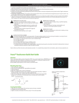
• Mounting the Adapter in large, straight, and open spaces maximizes range. For maximum signal strength, avoid mounting with one or
more blind bends between the Adapter and the end device or fixture. Autonomous bridging through devices in the space can be used to
overcome blind bends; this is done by following the recommendations in Section 2.
• The Adapter should be mounted vertically in the center of the chosen space, clear of any obstructions (metal or concrete obstructions are
3-1 Adapter Mounting Notes
Wireless adapter
installed on top or
underside of panel.
Wireless adapter
should NOT be
installed horizontally.
Upright or vertical
installation is
recommended.
Wireless adapter
NOT to be installed
inside the panel.
especially important to avoid).
• The cable for the Adapter is not plenum rated, so it should be routed through conduit
when ran through a plenum.
• Do not allow the Adapter to hang from its cord for a permanent installation.
• The Adapter has a 16’ cable. If a longer cable is required, use only those recommend-
ed by Acuity Brands. When using extender cables, 120V is required on the Adapter
side of the extension. Please see the FAQ for recommendations on extenders when
greater than 16’ is needed.
• Never mount the Adapter in an electrical closet.
• Be very mindful of metal — especially large metal equipment, electrical panels, and
metal objects hidden within the drywall. These will significantly reduce range in their
direction.
• Signal coverage may have gaps when created without a site visit. Using budgetary
ranges in Visual™ Controls (an Acuity Brands design tool) and inside of this guide will
help to mitigate risk of insufficient coverage.
• Try to avoid high angles of incidences with obstructions. RF is more capable of
penetrating an obstruction when approaching it straight on.
nLight AIR is a distributed-intelligence lighting control system. The nLight AIR parts and pieces communicate with other group
members to make decisions based on control inputs. Factors like ambient light conditions, occupancy status, switch presses, and
controller commands dictate the light levels in each area. If some or all the nLight AIR devices are not energized, they cannot
share control inputs or receive commands to change light levels.
nLight AIR is a system that must be permanently energized.
In retrofit applications, be sure to remove line-voltage switches, line-voltage occupancy sensors, automated contactor systems,
and other equipment that may interrupt power to the nLight AIR equipment.
4-1 General Operation and Power Requirements

11 of 14
Acuity Brands | One Lithonia Way Conyers, GA 30012 Phone: 800.535.2465 https://nlight.acuitybrands.com/ © 2020-2021 Acuity Brands Lighting, Inc. All rights reserved. Rev. 05/28/2021
nLight AIR Design Guide
Stand-Alone systems will always have a device assigned as a Group Monitor. Switch and battery powered devices should
communicate to the Group Monitor first, which will then broadcast to the rest of the devices. Non-battery/non-switch devices
may communicate with a Group Monitor via repeater devices using standalone autonomous bridging. The Group Monitor is
typically the center-most fixture or line-voltage device in the group, selected by the CLAIRITY™ Pro mobile application grid
placement and will not be a battery powered device. Should the Group Monitor fail, devices will communicate to all of the devices
4-2 System Architecture: Stand-Alone Systems
GM
GMGM
EXAMPLE 1 EXAMPLE 2
EXAMPLE 3 EXAMPLE 4
GM
X
X
X
X
X
X
in RF range, but because repeater devices are enabled and
managed by the group monitor, they will cease operating as
repeaters within 30 minutes of the Group Monitor failing.
Consider the examples to the right. In example 1, the user
presses a wall switch, which communicates to the Group
Monitor, which then broadcasts the command to the entire
group. In example 2, the Group Monitor does not respond to
forward the command, but the devices, still being in the RF
range of the broadcasting device, still function as expected. This
is considered recommended design practice.
In example 3, again, the user presses a wall switch, which
communicates to the Group Monitor, which then broadcasts
the command to the entire group. Through standalone
autonomous bridging, broadcasts from the Group Monitor could be repeated, too. In example 4, however, the Group Monitor has
failed, and since a number of the devices are outside the RF range of the broadcast device, they no longer function as expected.
Also because the Group Monitor has failed, repeaters will eventually deactivate and point-to-point communication from the
broadcasting device will be the only method of communication.
Therefore, for highest reliability, all devices in the group should be within the RF range of the broadcasting device, and very large
groups should not depend on the range of the Group Monitor or standalone autonomous bridging. Though losing the Group
Monitor as a point of redundancy will not cause issues for reservedly designed systems, it will make communication between
devices less reliable.

12 of 14
Acuity Brands | One Lithonia Way Conyers, GA 30012 Phone: 800.535.2465 https://nlight.acuitybrands.com/ © 2020-2021 Acuity Brands Lighting, Inc. All rights reserved. Rev. 05/28/2021
nLight AIR Design Guide
Consider the example below. There are three groups that have been networked to the same nLight ECLYPSE and Adapter. When
messages need to be sent out to the devices, the Adapter communicates directly to the devices through repeater devices by using
autonomous bridging technology. It does not necessarily route messages to the Group Monitor as is the case for stand alone
applications.
Global channels allow for greater versatility in nLight AIR systems. Please consider the below when using global channels for
communication between nLight Wired and nLight AIR devices or when using global channels for communication between nLight
AIR groups.
4-3 System Architecture: Networked Systems
4-4 System Architecture: Global Channel Best Practices
BROADCASTER
RECEIVER REPEATER
Features of Global Channels for AIR
Wired to AIR or AIR to Wired
• Intra-ECLYPSE switch, occupancy, and automatic daylight control dimming broadcasts
• Inter-ECLYPSE switch, occupancy, and inhibit photocell broadcasts
• Ability to control output devices in multiple groups or on different ports from one or more broadcasting devices
• Do not exceed more than two nLight Wired bridges (nBRG 8 devices) between the nLight ECLYPSE and the furthest Wired device. Each
nBRG 8 device adds ~75ms of latency between the nLight ECLYPSE and the end device.
• Repeats via autonomous bridging should be minimized to reduce latency. Each broadcast by an AIR repeater or Group Monitor will
cause ~50ms of latency.
• For personal spaces (such as private offices), the sum of all latency caused by nBRG 8 devices, Group Monitors, and AIR repeaters should
not exceed ~150ms. For this reason, global channel control of personal spaces is not recommended. Local control should be the basis
of design.
• For medium-sized spaces (such as open offices and conference rooms), the sum of all latency caused by nBRG 8 devices, Group Monitors,
and AIR repeaters is not recommended to exceed ~250ms.
• For large spaces (such as gymnasiums, warehouses, cafeterias, outdoor areas, and long corridors), the sum of all latency caused by nBRG
8 devices, Group Monitors, and AIR repeaters is not recommended to exceed ~500ms.
• It is not recommended to have both Wired and AIR output devices follow the same broadcasting device in small or medium spaces. This
is due to a ~150ms to ~250ms latency difference in messages received by the Wired and AIR devices, likely to result in asynchronous
response.
• For best performance, systems that use global channels should not make regular use of global profile scenes and numerous scheduled
profiles. Profile transmission by the nLight ECLYPSE takes priority over channeling, which will delay the rollout of a global channel.

13 of 14
Acuity Brands | One Lithonia Way Conyers, GA 30012 Phone: 800.535.2465 https://nlight.acuitybrands.com/ © 2020-2021 Acuity Brands Lighting, Inc. All rights reserved. Rev. 05/28/2021
nLight AIR Design Guide
• Global preset scene control of AIR output devices is not supported. Global preset scenes cannot be broadcast by AIR devices to affect
Wired devices.
• Global profile scenes can be triggered by Wired devices to control AIR devices. However, profiles are issued by an nLight ECLYPSE
through unicast messages (issued consecutively to one device at a time, quickly), which may result in asynchronous response from
output devices. This differs from broadcast messages, which result in uniform response from output devices.
• Global channels for Wired to AIR messages are only available for systems that do not make use of nGWY2 system controllers or the
Virtual WallPod plugin for SensorView.
AIR to AIR
• Repeats via autonomous bridging should be minimized to reduce latency. Each broadcast by an AIR repeater or Group Monitor will cause
~50ms of latency.
• For personal spaces (such as private offices), the sum of all latency caused by Group Monitors and AIR repeaters should not exceed
~150ms. For this reason, global channel control of personal spaces is not recommended. Local control should be the basis of design.
• For medium-sized spaces (such as open offices and conference rooms), the sum of all latency caused by Group Monitors and AIR repeat-
ers is not recommended to exceed ~250ms.
• For large spaces (such as gymnasiums, warehouses, cafeterias, outdoor areas, and long corridors), the sum of all latency caused by Group
Monitors and AIR repeaters is not recommended to exceed ~500ms.
• For best performance, systems that use global channels should not make regular use of global profile scenes and numerous scheduled
profiles. Profile transmission by the nLight ECLYPSE takes priority over channeling, which will delay the rollout of a global channel.
• Global channels for AIR to AIR messages are only available for systems that do not make use of nGWY2 system controllers or the Virtual
WallPod plugin for SensorView.

14 of 14
Acuity Brands | One Lithonia Way Conyers, GA 30012 Phone: 800.535.2465 https://nlight.acuitybrands.com/ © 2020-2021 Acuity Brands Lighting, Inc. All rights reserved. Rev. 05/28/2021
nLight AIR Design Guide
• What is the IP rating of the Adapter?
o The Adapter is IP66 rated.
• What is the temperature rating of the Adapter and nLight ECLYPSE?
o The nLight ECLYPSE is rated 0 to 50ºC and should be installed in an environmentally controlled area. The Adapter is rated -40 to 65ºC and can be
installed outdoors.
• Should the Adapter be mounted outside an electrical or IDF room?
o The Adapter should be placed with the fewest obstructions between it and the devices it is controlling. Placing the Adapter outside
an electrical or IDF room — such as in a hallway — is required and will allow the Adapter to communicate farther through the space.
• Should the Adapter be mounted to a wall? From the ceiling?
o The Adapter can be mounted to a wall or from the ceiling. These options are covered in the installation instructions. Generally,
mounting the Adapter in the center of a room is best.
• How do I extend the Adapter from the nLight ECLYPSE?
o The Adapter includes a 16 foot cable, but extension cables are available that can extend the Adapter an additional 150 feet.
An extender can be ordered using Acuity Brands part number NECYD EXT150 (CI Code - *268NEC).
• Can signals go through walls?
o RF can penetrate many different types of obstructions. However, some wall materials reduce the signal strength more than others.
Dry wall is penetrated more easily. Metal, reinforced concrete, and materials generally used on the exterior of a building (such as
brick) are difficult to penetrate. As identified in the design section, relying on line-of-sight communication, then reflections, and lastly
penetration will reduce the chance of insufficient signal strength.
• Can I use more than one Adapter per nLight ECLYPSE?
o Each nLight ECLYPSE can support only one Adapter at this time.
• Does RF go through glass?
o Yes, however glass with re-enforcing wire or low-E coating/film will reduce the RF more than regular glass.
• Can signals reflect to avoid a large obstruction?
o Yes, however, each material has different characteristics for signal absorption and reflection. Some materials may reflect more RF
than others.
• Should I use the Adapter to communicate to devices on separate floors?
o One Adapter should be used per floor. RF will not reliably penetrate the heavier-than-average construction required between floors.
• Can indoor and outdoor be in the same group? Or on one nLight ECLYPSE?
o It is recommended to use a separate nLight ECLYPSE and Adapter for the exterior and interior, unless the site is a retrofit or
renovation where a site survey can be done to confirm reliable RF communication across an exterior wall. See the below for more
information. Penetrating an exterior wall of a building is difficult and significantly reduces RF range, so for a reliable connection
and more range, separate nLight ECLYPSE controllers and Adapters are always needed for new construction.
• If working on a retrofit or renovation project and a site survey can be performed, is it possible to test and verify if a single nLight
ECLYPSE and Adapter can be used for both indoor and outdoor communication?
o Yes, it is possible to test and verify that a single Adapter can communicate with indoor and outdoor devices for retrofit or renovation applications by
using a site survey kit (NLTAIR SURVKIT - CI Code *2640U9). When using an indoor mounted Adapter to control outdoor fixtures or vice versa, one
hop is expended when broadcasting through an exterior wall, leaving the remaining hops for additional communication and distance.
• What are some examples of significant obstructions?
o Metal - metal equipment, metal-sided buildings, chain-link fence, wire mesh re-enforcement beneath stucco, re-enforcing wire in
windows in doors, large electrical panels, and metal HVAC ducts.
o Mirrors – Large mirrors are significant obstructions as they reflect RF.
o Exterior walls – brick, cinder block, and concrete.
o Stairwells – typical construction of a stairwell.
o Electrical rooms, IT rooms, and Mechanical rooms – made of various constructions that generally impede RF.
• What is the part number for an Adapter?
o The Acuity Brands part number is NECYD NLTAIR G2 (CI Code - *263L26). It is most often paired with the MVOLT version of the nLight ECLYPSE with an
enclosure, NECY MVOLT ENC (CI Code - *261WY0).
• How do I determine in the field if my Adapter placement is ideal?
o By using the CLAIRITY™ Pro application, signal strength between the Adapter and receiving devices can be measured. Instructions on measuring
signal strength can be found in the Clairity Pro user guide under Troubleshooting Tools, or they can be found in the nLight AIR Site Survey Kit’s
instruction guide.
5-1 Frequently Asked Questions
/