Page is loading ...

1 of 2
Acuity Brands | One Lithonia Way Conyers, GA 30012 Phone: 800.535.2465 www.acuitycontrols.com © 2014-2015 Acuity Brands Lighting, Inc. All rights reserved. August 24, 2015 10:57 AM
DOC# IN0012-005
Date Code 42115
1.800.535.2465
nLIGHT ENABLED DIGITAL
LUMINAIRE
PROGRAMMING INSTRUCTIONS
2 LUMEN COMPENSATION
An algorithm that tracks the LED luminaire’s
runtime and manages its light output to
maintain constant lumen output over the
system life.
3 IDLE TIME UNTIL DIM
The length of time after last detected occupancy
that the luminaire will reduce lighting level to
Unoccupied Dim Level setting.
5 SWITCH TRACKING CHANNEL
The channel on which the luminaire receives
switch information.
6 FOLLOW PHOTOCELL MODE
Directs the luminaire relative to a dimming
photocell in its zone.
7
SECONDARY ZONE DIMMING OFFSET
Percentage difference of unit’s dimming level
from its connected zone’s primary dimming
level (Function 6 must be enabled).
8
WALLPOD DIMMING ADJUSTMENTS
Defines whether user dimming adjustments
are maintained after lights are cycled, whether
they revert to preset levels, or whether they
temporarily disable a connected dimming
photocell (until lights cycle).
A-LEVEL FUNCTION DEFINITIONS
_______________________________
9 RESTORE FACTORY DEFAULTS
Returns all functions to original settings.
19 DIMMING RATE
The elapsed time over which changes to
dimming levels initiated via global or local
profile scenes are implemented. Note:
dimming level changes initiated via global
or local preset scenes are always immediate.
23 OCCUPIED BRIGHT LEVEL
The percentage of the controllable dimming
range up to which lights will rise when
occupancy is detected or the luminaire is
overridden on. Adjusting the dim level using
a WallPod changes this setting. When set at
100%, light level will match High End Trim
level. See function B31.
24 UNOCCUPIED DIM LEVEL
The percentage of controllable dimming
range to which lights manually or
automatically dim to, once the Idle Time
Until Dim timer expires. When set at 1%,
light level will match Low End Trim level. See
function B32.
B-LEVEL FUNCTION DEFINITIONS
__________________________________________
1 NAME UNIT w/ NUMBER
Applies a number to the default name visible in SensorView (useful during commisioning)
2 MANUAL ON (SEMI-AUTO) GRACE PERIOD
When in Manual On (Semi-Auto) mode (Function B-18), the time period after lights are automatically turned
off that they can be reactivated with movement
3 PREDICTIVE EXIT TIME (valid for Predictive Off mode only)
The time period after manually switching lights off for the occupant to leave the space
4 PREDICTIVE GRACE TIME (valid for Predictive Off mode only)
The time period after the Predictive Exit Time that the sensor rescans the room for remaining occupants
11 OCCUPANCY TRACKING
Indicates whether luminaire will react to occupancy information
12 OCCUPANCY TRACKING CHANNEL
The channel on which luminaire receives occupancy information
13 PHOTOCELL TRACKING
Indicates whether luminaire will react to photocell information
14 PHOTOCELL TRACKING CHANNEL
The channel on which luminaire receives photocell information
15 SWITCH TRACKING
Indicates whether luminaire will react to switch information
17 FORCED OVERRIDE
Indicates whether luminaire is forced to max level or off
18 SPECIAL OPERATING MODE
Unique defined behaviors of luminaire:
NORMAL
Operating Mode where occupancy sensors are capable of turning lights both on/off
SEMI-AUTO (MANUAL ON)
Special Mode that requires the occupant to manually turn the lights on, while having them turn off
automatically by a sensor
AUTO TO OVERRIDE ON
Special Mode where lights are turned on initially by occupant detection but remain in the Override On state
MANUAL ON TO FULL AUTO
Special Mode that initially requires the occupant to manually turn on the lights, after which the sensor
assumes full on/off control
PREDICTIVE OFF
When lights are switched off, sensor determines whether occupants remain or left the room, so as to leave the
lights in either the Override Off or Auto On state
MANUAL TO TIMED OVERRIDE ON
Special Mode where lights are initially turned on manually but remain in the Override On state for a pre-
determined period (Timed Override Delay)
MANUAL TO NORMAL
Special Mode where lights are initially turned on manually but remain in the Normal State (enabling auto-
dimming) for a pre-determined period (Timed Override Delay)
22 MAINTAIN DIM LEVEL WHEN VACANT
Prevents lights from turning fully off once in unoccupied state
23 SPECIAL SWITCH TRACKING MODE
Defines unique behavior related to how luminaire responds to particular switch information.
29 OCCUPANCY EXPIRATION of MANUAL OFF
When enabled, operation of device will revert from a push-button triggered override off state to Normal mode
once the Occupancy Time Delay (adjustable via SensorView or push-button) expires. Not used with Manual On
operating modes.
30 TIMED EXPIRATION of MANUAL OFF
When enabled, operation of device will revert from a push-button triggered override off state to Normal mode
once the Timed Override Delay (adjustable via SensorView) expires. Not used with Manual On operating
modes.
31 HIGH END TRIM
Maximum voltage level of the device’s dimming output. Commonly used for task tuning where absolute light
level is not to be increased via a Wallpod or scene. When output is at high end trim, the reported control
percentage will be 100%. Corresponding lumen output % is dependent on ballast/driver capabilities. Raising
setting above factory default is not recommended as default is optimized to driver control range.
32 LOW END TRIM
Minimum voltage level of the device’s active dimming range. Level can not be reduced via a WallPod or
scene. Note, voltage level may go below this level when device is given an OFF command (for example when
controlling LED drivers with sleep mode). When output is at low end trim, the reported control percentage
will be 1%. Corresponding lumen output % is dependent on ballast/driver capabilities. Lowering setting below
factory default is not recommended as default is optimized to driver control range.
PLEASE READ ALL 4 STEPS BEFORE PROGRAMMING
1. Enter A-Level programming mode by pressing button the number of times as the desired function number
from A-Level Detailed Function Tables below (e.g., press 5 times for function 5, Switch Tracking Channel).
2. The selected function’s current setting is indicated via LED flashes (e.g., 2 flashes
for Switch Tracking - Channel
2). To change, proceed to step 3 before it repeats 3 times.
3. While the sensor flashes back current setting, press the button the number of times for the new desired
setting as indicated in the detailed table (e.g., press 3 times for Switch Tracking - Channel 3). Sensor flashes
new setting as confirmation.
4. Programming mode exits automatically when setting sequence flashes back 3 times without interruption.
A-LEVEL PROGRAMMING INSTRUCTIONS
_________________________________
PROGRAMMING FUNCTIONS
____________________________________________________
A-LEVEL FUNCTIONS
2 Lumen Compensation
3 Idle Time Until Dim
5 Switch Tracking Channel
6 Follow Photocell Mode
7 Secondary Zone Dimming Offset
8 WallPod Dimming Adjustments
9 Restore Factory Defaults
19 Dimming Rate
23 Occupied Bright Level
24 Unoccupied Dim Level
B-LEVEL FUNCTIONS
1 Name Unit w/ Number
2 Manual On (Semi-Auto) Grace Period
3 Predictive Exit Time
4 Predictive Grace Time
11 Occupancy Tracking
12 Occupancy Tracking Channel
13 Photocell Tracking
14 Photocell Tracking Channel
15 Switch Tracking
17 Forced Override
18 Special Operating Mode
22 Maintain Dim Level When Vacant
23 Special Switch Tracking Mode
29 Occupancy Expiration of Manual Off
30 Timed Expiration of Manual Off
31 High End Trim
32 Low End Trim

2 of 2
Acuity Brands | One Lithonia Way Conyers, GA 30012 Phone: 800.535.2465 www.acuitycontrols.com © 2014-2015 Acuity Brands Lighting, Inc. All rights reserved. August 24, 2015 10:57 AM
PLEASE READ ALL 4 STEPS BEFORE PROGRAMMING
1. Enter B-Level programming mode by holding down button until status LED flashes rapidly, release, hold
down until rapid flash again, release, then immediately enter programming function as described in
step 2.
2. Enter a programming function by pressing button the number of times as the desired function number
from the B-Level Detailed Function Tables below (e.g., press twice for function 2, Semi-
Auto Grace Period).
3. Staus LED will flash back the selected function’s current setting (e.g., 3 flashes for 15 sec). To change
setting, proceed to step 3 before flash back sequence repeats 3 times. To exit the current function or to
change to a different function, wait for sequence to repeat 3 times and return to step 1.
4. Press button the number of times indicated in the particular function’s detailed table for the new
desired setting (e.g., press 1 time for 0 sec). As confirmation of setting change, status LED flashes back
the new setting 3 times before exiting.
INSTALLATION INSTRUCTIONS
NOTE:
For information on additional advanced settings, including resetting unit to factory
defaults, contact:
Technical Support: 1.800.535.2465
nPS 80 EZ
B-LEVEL PROGRAMMING INSTRUCTIONS
______________________________
B-LEVEL DETAILED FUNCTION TABLES
___________________________
*Indicates factory default unless dependent on model number.
** Setting precision of 0.1V is available via SensorView. Device status LED blinks out current value
rounded to nearest selection above.
1 = Name Unit w/ Number
1 1 3 3 5 5 7 7 9 9
2 2 4 4 6 6 8 8 10 Unassigned*
2 = Manual On (Semi-Auto) Grace Period
1 0 sec 3 15 sec*
3 = Predictive Exit Time
1 5 sec 3 7 sec 5 9 sec 7 15 sec 9 30 sec
2 6 sec 4 8 sec 6 10 sec* 8 20 sec
4 = Predictive Grace Time
1 0 sec 3 10 sec 5 30 sec 7 50 sec
2 5 sec* 4 20 sec 6 40 sec 8 60 sec
11 = Occupancy Tracking
1 Disable 2 Enable*
12 = Occupancy Tracking Channel
1 - 16 (e.g., 1 = Channel 1*; 2 = Channel 2; etc.)
13 = Photocell Tracking
1 Disable 2 Enable*
14 = Photocell Tracking Channel
1 - 16 (e.g., 1 = Channel 1*; 2 = Channel 2; etc.)
15 = Switch Tracking
1 Disable 2 Enable*
17 = Forced Override
1 Disabled (not forced)* 2 Override On 3 Override Off
18 = Special Operating Mode
1 Normal* 5 Predictive Off
2 Manual On 6 Manual to Override On
3 Auto to Override On 7 Manual to Normal
4 Manual to Full Auto
22 = Maintain Dim Level When Vacant
1 No* 2 Yes
23 = Special Switch Tracking Mode
1 Disable* 2 Ignore Offs 3 Ignore Ons 4 Ignore Ons & Offs
29 = Occupancy Expiration of Manual Off
1 Disabled* 2 Enabled
30 = Timed Expiration of Manual Off
1 Disabled* 2 Enabled
31 = High End Trim**
1 0.7V 3 2V 5 4V 7 6V 9 8V 11 10V
2 1V 4 3V 6 5V 8 7V 10 9V
32 = Low End Trim**
1 0.7V 3 2V 5 4V 7 6V 9 8V 11 10V
2 1V 4 3V 6 5V 8 7V 10 9V
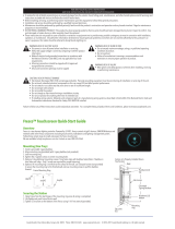
• Mount through a ½” knockout in any junction box or luminaire. Secure with lock nut.
• Following above wiring diagram, connect wires to line voltage feed(s), neutral(s),
and load.
• Connect low voltage violet and gray dimming wires to 0-10 VDC driver leads and
green wire to an approved ground connection. Note wires have 600V rated insula-
tion.
• Interconnect unit (via RJ-45 ports) with other nLight devices in lighting zone using
CAT-5e cables.
BUTTON
LED
RJ-45 PORTS
*Indicates Factory Default
A-LEVEL DETAILED FUNCTION TABLES
___________________________________________
2 = Lumen Compensation
1 Disabled (n100) 2 Enabled (n80)
3 = Idle Time Until Dim
1 30 sec 3 5 min 5 10 min 7 15 min 9 20 min
2 2.5 min 4 7.5* min 6 12.5 min 8 17.5 min
5 = Switch Tracking Channel
1 - 16 (e.g., 1 = Channel 1*; 2 = Channel 2; etc.)
6 = Follow Photocell Mode
1 Disable* 2 Enabled (Neg) 3 Enabled (Pos/Neg)
7 = Secondary Zone Dimming Offset
1 -100% 5 -60% 9 -20% 13 20% 17 60% 21 100%
2 -90% 6 -50% 10 -10% 14 30% 18 70%
3 -80% 7 -40% 11 0% * 15 40% 19 80%
4 -70% 8 -30% 12 10% 16 50% 20 90%
8 = WallPod Dimming Adjustments
1 Permanent* 2 Temporary 3 Photocell Temp. Override
9 = Restore Factory Defaults
1 Maintain Current* 2 Restore Defaults
19 = Dimming Rate
1 5 min 2 15 sec 3 5 sec* 4 2 sec 5 Instant
23 = Occupied Bright Level
1 1% 3 20% 5 40% 7 60% 9 80% 11 100%*
2 10% 4 30% 6 50% 8 70% 10 90%
24 = Unoccupied Dim Level
1 1%* 3 20% 5 40% 7 60% 9 80% 11 100%
2 10% 4 30% 6 50% 8 70% 10 90%
/