Page is loading ...

- 1 -
BOTTOM
OF SHOWER
74" FOR HEAD
CLEARANCE
1-5/8" TO 3-1/4"
48" TO 54"
OPTIONAL
12"
OPTIONAL
OPTIONAL
12"
OPTIONAL
1/2" NPT
1/2" NPT
1/2" SUPPLIES
PLUG TUB
OUTLET
6" DIA.
7" REF.
FINISHED WALL
8"
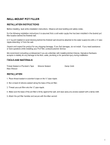
Universal Inlets / Outlets:
1/2" NOM Copper Sweat or 1/2" NPT
5-7/8"
1-1/4"
1/2" NPT
4" REF.
2-3/4" DIA.
OPTIONAL TO FINISHED
FLOOR USUALLY
BETWEEN 65" TO 78"
1/2"
48"
1-5/8"
36"
37-1/2"
FINISHED
WALL
3-1/8" DIA.
OPTIONAL TO FINISHED FLOOR
USUALLY BETWEEN
36" 60"
TO
3-1/8" DIA.
3-1/8" DIA.
1660766.002
(1.5 gpm)
1660767.002
(2.5 gpm)
3-5/16"
8-1/8"
1/2" NPSM
Certied to comply with ANSI A112.18.1
M985024 (5/19)
Product names listed herein are trademarks of AS America, Inc.
© AS America, Inc. 2019
Thank you for selecting American Standard...
the benchmark of fine quality for over 140 years.
To ensure that your installation proceeds smoothly-please read
these instructions carefully before you begin.
Installation must conform to all local building codes.
RECOMMENDED TOOLS & MATERIALS
ROUGHING-IN DIMENSIONS
COMMERCIAL SHOWER
SYSTEM KITS:
1.5 gpm & 2.5 gpm
INSTALLATION
INSTRUCTIONS
TU662SG.223
TU662SG.213
TU662SG.213
(1.5 gpm)
TU662SG.223
(2.5 gpm)
Electric Drill
Torch
6 mm (15/64")
Drill Bit
Pencil
Phillips Screwdriver Hammer
Adjustable Wrench
10'
Pipe Wrench Tubing Cutter
Tape Measure
Sealing Tape

- 2 -
2
1
M985024 (5/19)
INSTALL THE R422 TWO-WAY DIVERTER
NOTE: REFER TO INSTALLATION INSTRUCTIONS (M965673) SUPPLIED WITH
DIVERTER FOR COMPLETE INSTALLATION AND REPAIR PART INFORMATION.
IMPOR TANT: The reverse side of the body is marked with arrows.
CAUTI ON: Do not solder near the VALVE. Damage to the SEAL may occur. Do not seal
any outlets. The DIVERTER cannot be used as a stop valve. Use thread sealant
or sealing tape on threaded connections.
n See Roughing-in diagram before starting. The port with the BATH TUB picture is the high ow.
n The DIVERTER can be installed with the inlet rotated in any position.
n All connections are 1/2" NPT.
n For proper positioning the nished wall must be within the side of PLASTER GUARD.
n Connect the R422 TWO-WAY DIVERTER to the R120SS VALVE BODY.
TWO-WAY
DIVERTER
1/2" NPT INLET
1/2" NPT
SHOWER
1/2" NPT
HAND
SHOWER
MAKE ALL CONCEALED PIPING CONNECTIONS
n See Roughing-in diagram before starting.
n Make Hot and Cold supply connections to the VALVE BODY. Inlet and outlet connections to the valve body are 1/2" copper sweat.
n Make Tub Filler connection from DIVERTER. (Use the port with the BATH TUB picture). DIVERTER IS 1/2" NPT. TUB SPOUT
connection is 1/2" copper for SLIP-ON SPOUT.
n Make the connections for the HAND SHOWER. The HAND SHOWER connections are 1/2" NPT.
n For support, use PIPE BRACES secured to wooden braces. Cap off HAND SHOWER and TUB SPOUT FILLER PIPE.
With the R120SS VALVE turned off, turn on water supplies. Check for leaks.
n Finish all wall construction.
3
INSTALL VALVE TRIM AND SHOWER HEAD
UP
PLASTER GUARD
PLUG
H
C
Off
NOTE: REFER TO INSTALLATION INSTRUCTIONS (M965937)
SUPPLIED WITH VALVE TRIM KIT FOR COMPLETE
INSTALLATION AND REPAIR PART INFORMATION.
n When nished tiling the wall, remove PLASTER GUARD.
n Remove plug from shower pipe.

- 3 -
4
6
INSTALL WALL SUPPLY
INSTALL HOSE AND HAND SHOWER
TEST SHOWER SYSTEM
n Supply to WALL SUPPLY is 1/2" NPT. See rough-in above for
detailed information.
n Apply sealant or sealing tape to threads of 1/2" NPT supply nipple.
n Install SEAL (1) into COUPLING NUT (2). Connect
COUPLING NUT (2) to WALL SUPPLY NIPPLE (3)
and tighten.
n INSTALL second SEAL (4) into SPRAY HOSE END (5)
and connect HAND SHOWER (6) to SPRAY HOSE
END (5). Hand tighten.
n Turn on water supplies and check all fuctions of of the
SHOWER SYSTEM KIT. Check for any leaks.
M985024 (5/19)
1/2" NPT
APPLY SEALANT
OR SEALING TAPE
6
4
5
1
3
2
5
INSTALL DIVERTER TRIM AND HANDLE
PLASTER GUARD
1
5
6
7
8
9
2
4
3
n When nished tiling the wall, remove PLASTER GUARD.
n Place ESCUTCHEON (1) onto ESCUTCHEON HOLDER (2).
n Thread ESCUTCHEON HOLDER (2) onto DIVERTER VALVE (3).
Tighten until ESCUTCHEON (1) is snug against nished wall.
n Install HANDLE SKIRT (4) onto VALVE STEM (5).
n Push DECORATIVE RING (6) onto LEVER HANDLE (7).
n Align LEVER HANDLE (7) and push onto
HANDLE SKIRT (4). Install HANDLE
SCREW (8) and tighten.
n Push INDEX CAP (9) into
LEVER HANDLE (7).

- 4 -
OPTIONAL TO FINISHED FLOOR
USUALLY BETWEEN
FINISHED
FLOOR
915mm
(36")
1525mm
(60")
TO
914mm
(36")
2
LEVEL
VERTICAL
CENTER LINE
DRILLED
MOUNTING
HOLES
ROTATE
CLOCKWISE
TO LOCK
LOCK
UNLOCK
LARGE
DIAMETER UP
C/L
6
1 1
1
8
7
3
4
5
5
5
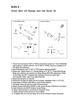
Fig. A Fig. B Fig. C
CARE INSTRUCTIONS:
DO: SIMPLY RINSE THE PRODUCT CLEAN WITH CLEAR WATER. DRY WITH A SOFT COTTON FLANNEL CLOTH.
DO NOT: DO NOT CLEAN THE PRODUCT WITH SOAPS, ACID, POLISH, ABRASIVES, HARSH CLEANERS, OR A CLOTH
WITH A COARSE SURFACE.
M985024 (5/19)
7
INSTALLATION INSTRUCTIONS
n The SLIDE BAR (1) works best when secured to the wall studs or cross brace using WOOD SCREWS. If mounting into
the studs is not possible, use appropriate wall fasteners provided to secure the installation.
n Mark a vertical center line in the location you wish to install the SLIDE BAR (1). NOTE: The height from the finished floor
is optional. See rough-in drawing for suggested dimensions.
n Determine desired height from the nished oor to the lower support and mark a horizontal center line. Slide the two
WALL ESCUTCHEONS (5) away from the MOUNTING FLANGES (3). Position the SLIDE BAR (1) as shown in Fig. A and
mark the location of the six mounting holes to be drilled. Fig. A. Using a #10 masonry drill, drill six mounting holes
1-1/4” max. deep. Fig. B.
n Install the six ANCHORS (2) provided into the mounting holes. Use a hammer to lightly tap ANCHORS (2) into place.
Make sure they are installed ush against the nished wall. Fig. B.
n Align and place the SLIDE BAR MOUNTING FLANGES (3) over the installed ANCHORS (2). Secure the SLIDE BAR (1)
to the wall with the SCREWS (4) provided. Fig. B.
n Push WALL ESCUTCHEONS (5) against nished wall. Rotate WALL ESCUTCHEONS (5) clockwise to lock into
position. Fig. C.
n Make sure larger diameter side of SPRAY HOLDER (6) is facing upward. If not rotate SPRAY HOLDER (6) 180 dergees.
Rotate the LEVER HANDLE (7) to the unlocked position. Push the SPRAY HOLDER (6) side onto the SLIDE BAR (1).
Push the LEVER HANDLE SIDE (7) over the SPRAY HOLDER ARMS (8) until the two snap together.
n Check operation of SLIDE BAR (1) by rotating HOLDER LEVER (7) and moving HAND SHOWER HOLDER (9) up and down.
Rotate LEVER HANDLE (7) back to lock HAND SHOWER HOLDER (6). Fig. B.
/