Page is loading ...


The products, technical information, and instructions contained in this manual are subject to change
without notice. These instructions are not intended to cover all details or variations of the equipment,
nor to provide for every possible contingency in the installation, operation or maintenance of this
equipment. This manual assumes that the person(s) working on the equipment have been trained
and are skilled in working with electrical, plumbing, pneumatic, and mechanical equipment. It is
assumed that appropriate safety precautions are taken and that all local safety and construction
requirements are being met, in addition to the information contained in this manual.
This Product is warranted only as provided in Cornelius’ Commercial Warrant applicable to this Prod-
uct and is subject to all of the restrictions and limitations contained in the Commercial Warranty.
Cornelius will not be responsible for any repair, replacement or other service required by or loss or
damage resulting from any of the following occurrences, including but not limited to, (1) other than
normal and proper use and normal service conditions with respect to the Product, (2) improper volt
-
age, (3) inadequate wiring, (4) abuse, (5) accident, (6) alteration, (7) misuse, (8) neglect, (9) unau-
thorized repair or the failure to utilize suitably qualified and trained persons to perform service and/or
repair of the Product, (10) improper cleaning, (11) failure to follow installation, operating, cleaning or
maintenance instructions, (12) use of “non-authorized” parts (i.e., parts that are not 100% compatible
with the Product) which use voids the entire warranty, (13) Product parts in contact with water or the
product dispensed which are adversely impacted by changes in liquid scale or chemical composition.
Contact Information:
To inquire about current revisions of this and other documentation or for assistance with any Corne-
lius product contact:
www.cornelius.com
800-238-3600
Trademarks and Copyrights:
This document contains proprietary information and it may not be reproduced in any way without per-
mission from Cornelius.
This document contains the original instructions for the unit described.
CORNELIUS INC
101 Regency Drive
Glendale Heights, IL
Tel: + 1 800-238-3600
Printed in U.S.A.

TABLE OF CONTENTS
Safety Instruction . . . . . . . . . . . . . . . . . . . . . . . . . . . . . . . . . . . . . . . . . . . . . . . . . . . . . 1
Read and Follow ALL Safety Instructions . . . . . . . . . . . . . . . . . . . . . . . . . . . . . . . . . 1
Safety Overview . . . . . . . . . . . . . . . . . . . . . . . . . . . . . . . . . . . . . . . . . . . . . . . . . . 1
Recognition . . . . . . . . . . . . . . . . . . . . . . . . . . . . . . . . . . . . . . . . . . . . . . . . . . . . . 1
Different Types of Alerts . . . . . . . . . . . . . . . . . . . . . . . . . . . . . . . . . . . . . . . . . . . . . . 1
Safety Tips . . . . . . . . . . . . . . . . . . . . . . . . . . . . . . . . . . . . . . . . . . . . . . . . . . . . . . . . 1
Qualified Service Personnel . . . . . . . . . . . . . . . . . . . . . . . . . . . . . . . . . . . . . . . . . . . 1
Safety Precautions . . . . . . . . . . . . . . . . . . . . . . . . . . . . . . . . . . . . . . . . . . . . . . . . . . 2
Shipping And Storage . . . . . . . . . . . . . . . . . . . . . . . . . . . . . . . . . . . . . . . . . . . . . . . . 2
CO
2
(Carbon Dioxide) Warning . . . . . . . . . . . . . . . . . . . . . . . . . . . . . . . . . . . . . . . . . 2
Mounting In Or On A Counter . . . . . . . . . . . . . . . . . . . . . . . . . . . . . . . . . . . . . . . . . . 2
Introduction . . . . . . . . . . . . . . . . . . . . . . . . . . . . . . . . . . . . . . . . . . . . . . . . . . . . . . . . . . 3
Description . . . . . . . . . . . . . . . . . . . . . . . . . . . . . . . . . . . . . . . . . . . . . . . . . . . . . . . . 3
Theory of Operation . . . . . . . . . . . . . . . . . . . . . . . . . . . . . . . . . . . . . . . . . . . . . . . . . 3
Specification . . . . . . . . . . . . . . . . . . . . . . . . . . . . . . . . . . . . . . . . . . . . . . . . . . . . . . . 3
Flow Diagram - Eight Valve Unit With Eight Line Cold Plate . . . . . . . . . . . . . . . . . . 4
Flow Diagram - Eight Valve Unit With Twelve Line Cold Plate . . . . . . . . . . . . . . . . . 5
Flow Diagram - Eight Valve Unit With Two Prism Valves . . . . . . . . . . . . . . . . . . . . . 6
Flow Diagram - Ten Valve Unit With Ten Line Cold Plate . . . . . . . . . . . . . . . . . . . . 7
Flow Diagram - Ten Valve Unit With Twelve Line Cold Plate . . . . . . . . . . . . . . . . . . 8
Flow Diagram - Ten Valve Unit With Twelve Line Cold Plate . . . . . . . . . . . . . . . . . . 9
E – Board Off Cycle Agitation Adjustments . . . . . . . . . . . . . . . . . . . . . . . . . . . . . . . 10
Wiring Diagram . . . . . . . . . . . . . . . . . . . . . . . . . . . . . . . . . . . . . . . . . . . . . . . . . . . . 11
Wiring Schematic . . . . . . . . . . . . . . . . . . . . . . . . . . . . . . . . . . . . . . . . . . . . . . . . . . 13
Maintenance . . . . . . . . . . . . . . . . . . . . . . . . . . . . . . . . . . . . . . . . . . . . . . . . . . . . . . . . 14
Daily (or as required) . . . . . . . . . . . . . . . . . . . . . . . . . . . . . . . . . . . . . . . . . . . . . . . . 14
Checking CO
2
Supply . . . . . . . . . . . . . . . . . . . . . . . . . . . . . . . . . . . . . . . . . . . . 14
Checking for CO
2
and water leak. . . . . . . . . . . . . . . . . . . . . . . . . . . . . . . . . . . . 14
Dispensing Valves . . . . . . . . . . . . . . . . . . . . . . . . . . . . . . . . . . . . . . . . . . . . . . . 14
Monthly . . . . . . . . . . . . . . . . . . . . . . . . . . . . . . . . . . . . . . . . . . . . . . . . . . . . . . . . . . 15
Beverage System (if applicable) . . . . . . . . . . . . . . . . . . . . . . . . . . . . . . . . . . . . . . . 15
Cold Plate. . . . . . . . . . . . . . . . . . . . . . . . . . . . . . . . . . . . . . . . . . . . . . . . . . . . . . 15
Sanitize syrup lines, B–I–B Systems . . . . . . . . . . . . . . . . . . . . . . . . . . . . . . . . . 15
Yearly . . . . . . . . . . . . . . . . . . . . . . . . . . . . . . . . . . . . . . . . . . . . . . . . . . . . . . . . . . . 16
Water Pump Maintenance (or after water system disruption) . . . . . . . . . . . . . . 16
Cleaning CO
2
Gas Check Valve . . . . . . . . . . . . . . . . . . . . . . . . . . . . . . . . . . . . 16
Motor Replacement . . . . . . . . . . . . . . . . . . . . . . . . . . . . . . . . . . . . . . . . . . . . . . . . . 17
Gearbox Replacement . . . . . . . . . . . . . . . . . . . . . . . . . . . . . . . . . . . . . . . . . . . . . . 19
Troubleshooting . . . . . . . . . . . . . . . . . . . . . . . . . . . . . . . . . . . . . . . . . . . . . . . . . . . . . 20
Diagnostics Guide for the Main Control Board . . . . . . . . . . . . . . . . . . . . . . . . . . . . 23
Troubleshooting . . . . . . . . . . . . . . . . . . . . . . . . . . . . . . . . . . . . . . . . . . . . . . . . . . . 24
Beverage Not Dispensing . . . . . . . . . . . . . . . . . . . . . . . . . . . . . . . . . . . . . . . . . 24


IDC 2XX Service Manual
© 2007-2019, Cornelius Inc. - 1 - Publication Number: 621057403SER
SAFETY INSTRUCTION
READ AND FOLLOW ALL SAFETY INSTRUCTIONS
Safety Overview
• Read and follow ALL SAFETY INSTRUCTIONS in this manual and any warning/caution labels on the unit
(decals, labels or laminated cards).
• Read and understand ALL applicable OSHA (Occupational Safety and Health Administration) safety regulations
before operating this unit.
Recognition
DIFFERENT TYPES OF ALERTS
!
DANGER:
Indicates an immediate hazardous situation which if not avoided WILL result in serious injury, death or equipment damage.
!
WARNING:
Indicates a potentially hazardous situation which, if not avoided, COULD result in serious injury, death, or equipment
damage.
CAUTION:
!
Indicates a potentially hazardous situation which, if not avoided, MAY result in minor or moderate injury or equipment
damage.
SAFETY TIPS
• Carefully read and follow all safety messages in this manual and safety signs on the unit.
• Keep safety signs in good condition and replace missing or damaged items.
• Learn how to operate the unit and how to use the controls properly.
• Do not let anyone operate the unit without proper training. This appliance is not intended for use by very young children or
infirm persons without supervision. Young children should be supervised to ensure that they do not play with the appliance.
• Keep your unit in proper working condition and do not allow unauthorized modifications to the unit.
QUALIFIED SERVICE PERSONNEL
!
WARNING:
Only trained and certified electrical, plumbing and refrigeration technicians should service this unit. ALL WIRING
AND PLUMBING MUST CONFORM TO NATIONAL AND LOCAL CODES. FAILURE TO COMPLY COULD
RESULT IN SERIOUS INJURY, DEATH OR EQUIPMENT DAMAGE.
Recognize Safety Alerts
This is the safety alert symbol. When you see it in this manual or on the unit,
be alert to the potential of personal injury or damage to the unit.
!

IDC 2XX Service Manual
Publication Number: 621057403SER - 2 - © 2007-2019, Cornelius Inc.
SAFETY PRECAUTIONS
This unit has been specifically designed to provide protection against personal injury. To ensure continued protection
observe the following:
!
WARNING:
Disconnect power to the unit before servicing following all lock out/tag out procedures established by the user. Verify
all of the power is off to the unit before any work is performed.
Failure to disconnect the power could result in serious injury, death or equipment damage.
CAUTION:
!
Always be sure to keep area around the unit clean and free of clutter. Failure to keep this area clean may result in
injury or equipment damage.
SHIPPING AND STORAGE
CAUTION:
!
Before shipping, storing, or relocating the unit, the unit must be sanitized and all sanitizing solution must be drained
from the system. A freezing ambient environment will cause residual sanitizing solution or water remaining inside the
unit to freeze resulting in damage to internal components.
CO2 (CARBON DIOXIDE) WARNING
!
DANGER:
CO2 displaces oxygen. Strict attention MUST be observed in the prevention of CO2 gas leaks in the entire CO2 and
soft drink system. If a CO
2 gas leak is suspected, particularly in a small area, IMMEDIATELY ventilate the
contaminated area before attempting to repair the leak. Personnel exposed to high concentrations of CO
2 gas
experience tremors which are followed rapidly by loss of consciousness and DEATH.
MOUNTING IN OR ON A COUNTER
!
WARNING:
When installing the unit in or on a counter top, the counter must be able to support a weight in excess of 600 lbs. to
insure adequate support for the unit. FAILURE TO COMPLY COULD RESULT IN SERIOUS INJURY, DEATH OR
EQUIPMENT DAMAGE.
NOTE: Many units incorporate the use of additional equipment such as ice makers. When any addition
equipment is used you must check with the equipment manufacturer to determine the addi
-
tional weight the counter will need to support to ensure a safe installation.

IDC 2XX Service Manual
© 2007-2019, Cornelius Inc. - 3 - Publication Number: 621057403SER
INTRODUCTION
DESCRIPTION
The IDC series of ice dispensers solves your ice and beverage service needs in a sanitary, space saving,
economical way. Designed to be automatically filled with ice from a top mounted ice machine or manually filled with
ice from any remote ice-making source, these dispensers will dispense cubes (up to 1-1/4 inch in size), cubelets,
and compressed or extruded style ice. In addition, the units include beverage faucets, a cold plate, an internal
carbonator tank and an external pump for the carbonator, and are designed to be supplied direct from syrup tanks
with no additional cooling required.
THEORY OF OPERATION
The rate of CO
2
solubility increases with cold water. IDC System provides pre–chilled cold water from the cold plate
and mix with CO
2
in the carbonator tank. The water is introduced into the tank with a high volume 125gph Procon
pump and high torque motor.
The amount of carbonated water reserve is controlled by a probe mounted in the tank. The probe is called a “liquid
le
vel probe”. The liquid level probe senses the water level in the tank. Probe controls the pump “ON” and “OFF”
cycle through the “liquid level board” located on the main control board.
NOTE: The probe works on a 5 mVDC current that continually reverses direction to prevent probe
co
rrosion.
SPECIFICATION
Model Descriptions: IDC 215
B=Beverage
C=Coldplate
H=Internal Carb
Z=No Drip Tray
IDC 255
B=Beverage
C=Coldplate
H=Internal Carb
Z=No Drip Tray
Ice Storage: 215 Pounds 255 Pounds
Maximum Number of Faucets
Availa
ble:
10 10
Built–in Cold Plate: Yes Yes
Electrical: 120/1/60,
9.3 A
mps of Total Unit Draw
220/1/50,
4.7 Amps of Total Unit Draw
Dimensions:
Width
Depth
Height
30 inch
30-11/16 inch
36 inch (to top of bin)
36-3/4 inch (to top of lid)
30 inch
30-11/16 inch
39 inch (to top of bin)
39-3/4 inch (to top of lid)
CO
2
Operating Pressure 75-psig (max) 75-psig (max)

IDC 2XX Service Manual
Publication Number: 621057403SER - 4 - © 2007-2019, Cornelius Inc.
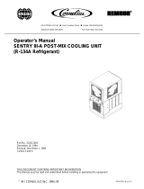
FLOW DIAGRAM - EIGHT VALVE UNIT WITH EIGHT LINE COLD PLATE
THIS EQUIPMENT MUST BE INSTALLED WITH ADEQUATE BACKFLOW PROTECTION
TO COMPLY WITH APPLICABLE FEDERAL, STATE AND LOCAL CODES.
S8
S7
S6
S5
S4
S3
S2
S1
CO2 SOURCE
100-110 PSIG
SECONDARY REGULATOR
CO2
CYLINDER
SYRUP BIB'S
60 PSIG
PUMP & MOTOR ASY
PRESSURE
REGULATOR
OR BOOSTER
PUMP MAY BE
REQUIRED
CITY
WATER
FIXED REGULATOR
ICE
CHUTE
COLDPLATE
CW
PW
CW
PW
CARB TANK OUT
CARB TANK IN
CARB WTR IN
PLAIN WTR IN
IN
OUT
CARB
TANK
2
4
W3
W2
W2W1
7
6
W3
W2
W3
W1
4
3
2
1
8
7
6
5
PW = PLAIN WATER
CW = CARBONATED WATER
VALVES
2
34
5
6
7
TOTAL
FLEX
MANIFOLD
TOTAL
FLEX
MANIFOLD
CW
PW
CW
PW
8
INCLUDED WITH UNIT
8
1
3
5
1
WATER
FILTER
figure 1.

IDC 2XX Service Manual
© 2007-2019, Cornelius Inc. - 5 - Publication Number: 621057403SER
FLOW DIAGRAM - EIGHT VALVE UNIT WITH TWELVE LINE COLD PLATE
figure 2

IDC 2XX Service Manual
Publication Number: 621057403SER - 6 - © 2007-2019, Cornelius Inc.
FLOW DIAGRAM - EIGHT VALVE UNIT WITH TWO PRISM VALVES
figure 3

IDC 2XX Service Manual
© 2007-2019, Cornelius Inc. - 7 - Publication Number: 621057403SER
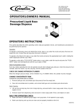
FLOW DIAGRAM - TEN VALVE UNIT WITH TEN LINE COLD PLATE
THIS EQUIPMENT MUST BE INSTALLED WITH ADEQUATE BACKFLOW PROTECTION
TO COMPLY WITH APPLICABLE FEDERAL, STATE AND LOCAL CODES.
S8
S7
S6
S5
S4
S3
S2
S1
CO2 SOURCE
100-110 PSIG
SECONDARY REGULATOR
CO2
CYLINDER
SYRUP BIB'S
60 PSIG
PUMP & MOTOR ASY
PRESSURE
REGULATOR
OR BOOSTER
PUMP MAY BE
REQUIRED
CITY
WATER
FIXED REGULATOR
ICE
CHUTE
COLDPLATE
CW
PW
CW
PW
CARB TANK OUT
CARB TANK IN
CARB WTR IN
PLAIN WTR IN
IN
OUT
CARB
TANK
4
5
W3
W2
W2W1
8
9
W3
W2
W3
W1
5
4
3
2
9
8
7
6
PW = PLAIN WATER
CW = CARBONATED WATER
VALVES
2
TOTAL
FLEX
MANIFOLD
TOTAL
FLEX
MANIFOLD
CW
PW
CW
PW
10
INCLUDED WITH UNIT
1
3
7
1
WATER
FILTER
345
768910
2
6
1
10
S10
S9
figure 4.

IDC 2XX Service Manual
Publication Number: 621057403SER - 8 - © 2007-2019, Cornelius Inc.
FLOW DIAGRAM - TEN VALVE UNIT WITH TWELVE LINE COLD PLATE
figure 5

IDC 2XX Service Manual
© 2007-2019, Cornelius Inc. - 9 - Publication Number: 621057403SER
FLOW DIAGRAM - TEN VALVE UNIT WITH TWELVE LINE COLD PLATE
figure 6

IDC 2XX Service Manual
Publication Number: 621057403SER - 10 - © 2007-2019, Cornelius Inc.
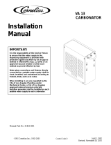
E – BOARD OFF CYCLE AGITATION ADJUSTMENTS
When Ice is not being dispensed from the machine such as during off hours it is essential to move or agitate the ice
to keep it from clumping and to replenish the ice in the cold plate. The amount of time the agitator runs and the time
between the agitation cycles can be adjusted depending on ice type or application. The settings for this function
are located on the E-Board found in the E-BOX. Using a screwdriver follow the diagram below and set the agitator
for the desired settings.
E-BOARD AGITATION TIMER
2
HRS
1.5
HRS
1
HR
30
MIN
10
MIN
3
HRS
MOTOR ON TIME
OFF TIME
4.5
4
3.5
3
2.5
2
1.5
1
.5
5
2.5
HRS
FULL CCW - 0.5 SECONDS
FULL CW - 5 SECONDS
FULL CCW - 10 MINUTES
FULL CW - 3 HOURS
ON
TIME
OFF
TIME
ON
TIME
OFF
TIME
figure 7
Manufacturer Recommended Agitation Settings
Model Ice Fill/Ice Type Motor ON Time Motor OFF time
175, 215,
&25
5, 300,
B, BC
Manual/Hard Ice (Cube) 4 Seconds 1 Hour
Automatic (Top-Mount Ice
Ma
ker/Hard Ice (Cube)
0.5 Seconds 20 Minutes
Manual & Automatic/
Cornelius Chunklet,
Scotsman
& Hoshizaki
Compressed Ice
0.5 Seconds 3 Hours
B - Beverage C-Coldplate *NO FLAKED ICE*

IDC 2XX Service Manual
© 2007-2019, Cornelius Inc. - 11 - Publication Number: 621057403SER
WIRING DIAGRAM
figure 8.

IDC 2XX Service Manual
Publication Number: 621057403SER - 12 - © 2007-2019, Cornelius Inc.
WIRING SCHEMATIC
BLK
CARB TANK
E-BOARD
J3
VALVE
KEY
LOC
VALVE
24V Sec
XFRMR2
VALVE
KEY
LOC
VALVE
24V Sec
XFRMR1
120V Pri
120V Pri
80 VA
80 VA
E-BOARD
XFORMER_L1
L1_HEATER
L1_BALLAST
E-BOARD
L2_XFORMER
HEATER_L2
BALLAST_L2
HEATER
BALLAST
STARTER
FLOURESCENT LIGHT
OPTIONAL LIGHTING
AGITATOR_L2
AGITATOR MOTOR
AGITATOR
AGITATOR EARTH
CARB MOTOR
CARB MOTOR
CARB_MOTOR_L2
CARB EARTH
L2_IN
L2
L1_1N
L1
EARTH
ICE GATE SWITCH
figure 9

IDC 2XX Service Manual
© 2007-2019, Cornelius Inc. - 13 - Publication Number: 621057403SER
MAINTENANCE
The following dispenser maintenance should be performed at the intervals indicated:
DAILY (OR AS REQUIRED)
Remove foreign material from vending area drip tray to prevent drain blockage.
Clean vending area. Check for proper water drainage from the vending area drip tray.
Checking CO
2
Supply
Make sure CO
2
cylinder regulator assembly 1800-psi gage indicator is not in shaded (“change CO
2
cylinder”)
portion of the dial. If so, the CO
2
cylinder is almost empty and must be replaced.
Replenishing CO
2
Supply
NOTE: When indicator on the 1800-psi gage is in the shaded (“change CO
2
cylinder”) portion of
the dial, CO
2
cylinder is almost empty and should be changed.
1. Fully close (clockwise) the CO
2
cylinder valve.
2. Slowly loosen the CO
2
regulator assembly coupling nut allowing CO
2
pressure to escape, then
remove the regulator assembly from the empty CO
2
cylinder
.
3. Unfasten safety chain and remove the empty CO
2
cylinder.
WARNING: To avoid personnel injury and/or property damage, always secure the CO
2
cylinder with
a safety chain to prevent it from falling
over. Should the valve become accidentally damaged or
broken off, a CO
2
regulator can cause serious personnel injury.
4. Position the full CO
2
cylinder and secure with a safety chain.
5. Make sure gasket is in place inside the CO
2
regulator assembly coupling nut, then install the
regulator assembly on the CO
2
cylinder.
6. Open (counterclockwise) the CO
2
cylinder valve slightly to allow the lines to slowly fill with gas, then
open the valve fully to back-seat the valve (back-seating the valve prevents gas leakage around the
valve shaft).
7. Check CO
2
connections for leaks. Tighten any loose connections.
Checking for CO
2
and water leak
Check the Unit for CO
2
and water leaks and if found, call a qualified Service Person to repair as necessary.
Dispensing Valves
Refer to addendum supplied with the unit that is applicable to the manufacturer of the valves installed
on the unit.
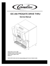
Cleaning Dispensing Valve
1. Remove nozzle assembly (contains Inner Nozzle) from
dispensing valve. Separate the inner nozzle
from the nozzle and wash the two parts in warm water.
2. Remove the bottom plate by releasing the two snap-fit clips. Remove
the lever from the bottom
plate and wash the bottom plate and the lever in warm water.
3. Reassemble the lever into the bottom plate and ret
urn the bottom plate to the valve. Be sure the
rear tabs are properly secured.

IDC 2XX Service Manual
Publication Number: 621057403SER - 14 - © 2007-2019, Cornelius Inc.
4.
BOTTOM
PLATE P/N
1903
O
F
F
SNAP FIT CLIP
REAR
TAB
SNAP FIT
CLIP
INNER
NOZZLE
NOZZLE
SNAP FIT
CLIP
SNAP FIT
CLIP
Return the inner nozzle to the nozzle and replace the assembly to the valve.
MONTHLY
Clean and sanitize the hopper interior and beverage system, if applicable (see CLEANING INSTRUCTIONS).
BEVERAGE SYSTEM (IF APPLICABLE)
WARNING: Disconnect Power Before Cleaning! Do no use metal scrapers, sharp objects, or
abrasives on the ice storage hopper, top cover and the
agitator disk, as damage may result. Do not
use solvents or other cleaning agents, as they may attack the plastic material.
• Soap solution – Use a mixture of mild detergent and warm (100
o
F) potable water.
• Sanitizing solution – Dissolve 2 packets (4 oz.) Stera Sheen Green Label into 2 gallons of warm (80-
10
0
o
F) water to ensure 200 ppm of available chlorine.
• Cleaning tank – Fill clean, empty tank with a mixture of
mild detergent and five (5) gallons of warm
potable water (120
o
F).
CAUTION: When pouring liquid into the hopper, do not exceed the rate of 1/2 gallon per minute.
Cold Plate
1. Remove splash panel.
2. Remove or move the plastic cold plate cover to expose the cold plate.
3. Locate and remove any debris from the drain trough. Check that the drain holes are not clogged.
4. Pour small amount of soap solution through cold plate openings in hopper.
5. Using a cloth, wash down the surfaces of the cold
plate and plastic cover with soap solution.
6. Install and properly position the access covers on
the cold plate.
7. Install the splash panel in the reverse order it was removed.
8. Rinse cold plate surface by pouring potable water through hopper openings.
Sanitize syrup lines, B–I–B Systems
1. Remove all the quick disconnects from all the B–I–B containers.
2. Fill a suitable pail or bucket w
ith soap solution.
3. Submerge all disconnects (gas and liquid) in the soap solution and then clean them using a nylon
b
ristle brush. (Do not use a wire brush). Rinse with clean water.
4. Using a plastic pail, prepare approximately five (5
) gallons of sanitizing solution.

IDC 2XX Service Manual
© 2007-2019, Cornelius Inc. - 15 - Publication Number: 621057403SER
5. Rinse the B–I–B disconnects in the sanitizing solution.
6. Sanitizing fittings must be attached to each B–I–B disconnect. If these fittings are not available, the
fittings from empty B–I–B bags can be cut from the bags and used. These fittings open the
disconnect so the sanitizing solution can be drawn through the disconnect.
7. Place all the B–I–B disconnects into the pail of sanitizing solution. Operate all the valves until the
sanitizing solution is flowing from the valve. Allow sanitizer to remain in lines for fifteen (15) minutes.
8. Remove the nozzle and syrup diffuser from each valve and clean them in a soap solution. Rinse
with clean water and reassemble the nozzle and syrup diffuser to the valve.
9. Remove the sanitizing fittings from the B–I–B disconnects and connect the disconnects to the
appropriate
B–I–B container. Operate the valves until all sanitizer has been flushed from the system and syrup
is flowing freely.
YEARLY
Water Pump Maintenance (or after water system disruption)
The water pump water strainer screen and the liquid dual check valve must be inspected and cleaned at least
once a year under normal circumstances and after any water system disruption (plumbing work, earthquake,
etc.). Call a qualified Service Person to inspect and clean the strainer screen and the liquid dual check valve.
Cleaning CO
2
Gas Check Valve
The CO
2
gas check valve, located on the carbonated water tank, must be inspected and serviced at least once
a year under normal conditions and after any CO
2
system servicing disruption. Call a qualified Service Person
to inspect and clean the CO
2
gas check valve.

IDC 2XX Service Manual
Publication Number: 621057403SER - 16 - © 2007-2019, Cornelius Inc.
MOTOR REPLACEMENT
Remove the 4 screws with a 1/4” socket to
separate the agitator motor from the gear
box.
1.
Remove (4)
Screws
Agitator
Motor
Gear Box
2. Remove the agitator motor.
3. Install the new agitator motor and replace
th
e screws removed in step 1 with a 1/4”
socket.
/