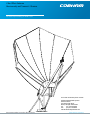
COBHAM 3.8m Offset Antenna Installation guide
- Type
- Installation guide
COBHAM 3.8m Offset Antenna is a high-quality device designed for receiving and transmitting signals. It is commonly used in satellite communication systems and can be employed in various applications, such as:
- Television and radio broadcasting
- Data transmission
- Internet access
- Military and government communications The antenna features a robust construction and is built to withstand harsh weather conditions, making it suitable for outdoor installations. Its 3.

For further information please contact:
Cobham SATCOM land Systems
Patriot Products
704 North Clark Street
Albion, Michigan 49224 USA
Tel: (01) 517 629 5990
Fax: (01) 517 629 6690
www.cobham.com/patriot
3.8m Oset Antenna
Receive only and Transmit / Receive
The most important thing we build is trust
Document number here in this font and color

2
www.cobham.com/patriot
This COBHAM SATCOM Patriot product is warranted to be free from defects in material and
workmanship under normal use and service. Patriot antenna products shall repair or replace defective
equipment, at no charge, or at its option, refund the purchase price, if the equipment is returned to Patriot
products not more than twelve (12) months after shipment. Removal or reinstallation of equipment and its
transportation shall not be at cost of COBHAM SATCOM Patriot product except Patriot product shall return
repaired or replaced equipment freight prepaid.
This Warranty shall not apply to equipment which has been repaired or altered in any way so as to affect
its stability or durability, or which has been subject to misuse, negligence or accident. This Warranty does
not cover equipment which has been impaired by severe weather conditions such as excessive wind, ice,
storms, lightning, or other natural occurrences over which COBHAM SATCOM Patriot products has no
control, and this Warranty shall not apply to equipment which has been operated or installed other than in
accordance with the instructions furnished by COBHAM SATCOM Patriot products.
Claimants under this Warranty shall present their claims along with the defective equipment to COBHAM
SATCOM Patriot products immediately upon failure. Noncompliance with any part of this claim procedure
may invalidate this warranty in whole or in part.
THIS WARRANTY IS EXPRESSLY IN LIEU OF ALL OTHER AGREEMENTS AND WARRANTIES, ANY IMPLIED
WARRANTY OF MERCHANTABILITY OR FITNESS FOR A PARTICULAR PURPOSE IS LIMITED IN DURATION
TO THE DURATION OF THIS WARRANTY. PATRIOT ANTENNA DOES NOT AUTHORIZE ANY PERSON TO AS-
SUME FOR IT THE OBLIGATIONS CONTAINED IN THIS WARRANTY AND
PATRIOT ANTENNA NEITHER ASSUMES NOR AUTHORIZES ANY REPRESENTATIVE OR OTHER
PERSON TO ASSUME FOR IT ANY OTHER LIABILITY IN CONNECTION WITH THE EQUIPMENT
DELIVERED OR PROVIDED.
IN NO EVENT SHALL COBHAM SATCOM PATRIOT ANTENNA PRODUCTS BE LIABLE FOR ANY LOSS OF
PROFITS, LOSS OF USE, INTERRUPTION OF BUSINESS, OR INDIRECT, SPECIAL OR
CONSEQUENTIAL DAMAGES OF ANY KIND.
In no event shall COBHAM SATCOM Patriot products be liable for damages in an amount greater than the
purchase price of the equipment.
Some states do not allow limitations on how long an implied warranty lasts, or allow the exclusion or
limitation of incidental or consequential damages, so the above limitations or exclusions may not apply to
you.
COBHAM SATCOM Patriot products has the right to void the warranty when the antenna is installed by
someone other then a certied installer.
LIMITED TWELVE (12) MONTH WARRANTY
Product Serial Number- _________________
Date Purchased- _________________
Cobham SATCOM Land Systems
Patriot Products
704 North Clark Street
Albion, MI 49224 USA
Tel: (517)629-5990
Fax: (517)629-6690

3
www.cobham.com/patriot
1. Perform as many functions as possible on the ground.
2. Watch out for overhead power lines. Check the distance to the power lines before starting
installation.
We recommend you stay a minimum of 6 meters (20 feet) from all power lines.
3. Do not use metal ladders.
4. Do not install antenna or mast assembly on a windy day.
5. If you start to drop antenna or mast assembly, get away from it and let if fall.
6. If any part of the antenna or mast assembly comes in contact with a power line, call your
local power company. DO NOT TRY TO REMOVE IT YOURSELF! They will remove it safely.
7. Make sure that the mast assembly is properly grounded.
WARNING
Assembling dish antennas on windy days can be dangerous. Because of the antenna surface,
even slight winds create strong forces. For example, a 1.0m antenna facing a wind of 32 km/h
(20 mph) can undergo forces of 269 N (60 lbs.). Be prepared to safely handle these forces at un-
expected moments. Do not attempt to assemble, move or mount dish on windy days or serious,
even fatal accidents may occur. COBHAM SATCOM Patriot antenna product is not responsible or
liable for damage or injury resulting from antenna installations.
INSTALLATION OF THIS PRODUCT SHOULD BE PERFORMED ONLY BY A PROFES-
SIONAL INSTALLER AND IS NOT RECOMMENDED FOR CONSUMER D.I.Y.
(DO-IT-YOURSELF) INSTALLATIONS.
IMPORTANT!!!
WATCH FOR WIRES!
Installation of this product near power lines is dangerous. For your
own safety, follow these important safety rules.

4
www.cobham.com/patriot
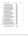
Item# Part Description Part Numbe Quantity
1 ASSY, 3.8M OFFSET A-LEFT PANEL 238204 1
2 ASSY,3.8M OFFSET A-RIGHT PANEL 238205 1
3 ASSY,3.8M OFFSET B PANEL 238206 2
4 ASSY,3.8M OFFSET C-LEFT PANEL 238208 1
5 ASSY,3.8 MTR OFFSET C-RIGHT PANEL 238209 1
6 ASSY,3.8M OFFSET RADIAL BEAM A 238210 1
7 ASSY,3.8M OFFSET RADIAL BEAM B 238211 4
8 ASSY,3.8M OFFSET RADIAL BEAM C 238213 2
9 ASSY,3.8M OFFSET 90” BACK SUPPORT 238223 2
10 ASSEM, CURFING 42.68” “B” 238910 2
11 ASSEM, CURFING 46.79” “A” 238911 2
12 ASSEM, CURFING 57.00” “C” 238912 2
13 TUBE,3.8M OFFSET FEED SUPPORT 238993 2
14 ASSEM, 3.8M OFFSET FEED PLATE 238996 1
15 MOUNT,3.8M OFFSET KINGPST AND YOKE 238308 1
16 ASSY,3.8M OFFSET MAST STRUT 238307 1
17 ASSY,3.8 MTR OFFSET HUB 238214 1
18 ASSY,3.8M OFFSET KP ELEV.ROD 238302 1
PG 7 PLATE,3.8M OFFSET KP AZ LOCKDOWN 238304-04 1
PG 7 ASSY,3.8M OFFSET KP AZ LOCKDOWN 238304 1
PG 7 ASSY,3.8M OFFSET KP AZIMUTH ROD 238303 1
PG 9 SHIM, 2.4M BOOM .25” 224132 4
PG10 ANGLE,3.8M OFFSET HUB 238214-12 28
PG11 ASSY,3.8M OFFSET 65” BACK SUPPORT L 238224 1
PG11 BRKT.,3.8M OFFSET BACK SUPPORT 238222 21
PG11 ANGLE,3.8M 45”BACK SUPPORT 238219 4
PG11 ASSY,3.8M OFFSET 65” BACK SUPPORT R 238225 1
PG11 ANGLE,3.8M 32” BACK SUPPORT 238220 4
PG11 ASSY,3.8M OFFSET 65” BACK SUPPORT L 238224 1
PG11 ASSY,3.8M OFFSET 65” BACK SUPPORT R 238225 1
PG11 ANGLE,3.8M OFFSET 90” BACK SUPPORT 238223 2
PREBAG,3.8M.OFFSET REFLECTOR HWD. 3HP38011 1
PAINT, OFF WHITE TOUCH UP, 8 OZ. 4M9055 1

5
www.cobham.com/patriot
Grounding Rod Clamp & Grounding Block - As required by
National Electric Code or local codes.
Ground Wire - #10 solid copper or as required by National
Electric Code or local codes.
Coaxial Cable (Size & Length required).
Concrete & Rebar (See Foundation Appendix A).
Preinstallation materials checklist
1- 5/32”, 3/16” , 1/4” allen wrenches
2- Combination wrenches -
7/16”, 1/2”, 9/16”, 3/4”, 15/16”, 1-1/8”
1- Large Crescent wrench or Pipe Wrench with
3in. jaw opening
1- Inclinometer (for sighting in)
1- Compass (for sighting in)
1- Impact drill
(for drilling cement anchor holes)
6
Tools Needed
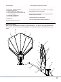
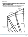
Reference Drawing
Refer to Parts and Hardware list on page 5 for part descriptions. This figure is an overall assembled an-
tenna and can assist the installer with locating parts and understanding the relationship between compo-
nents.
2
12
13
11
4
1
20
18
17
19
14
5
6
7
8
9
10
15
16
23
24
25
8
7
9
6
10
11
12
13
14
15
1
2
5
4
3
3
17
16
18

6
www.cobham.com/patriot
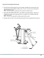
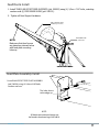
1. Place the King Post Mast assembly onto the foundation threaded rods and secure with nuts
and washers from the foundation hardware pack. Be sure to use the 4-base reinforcement
plates provided as shown.
NOTE: The mast should be pointed due south (northern hemisphere sites)
2. Attach ASSY,3.8M OFFSET MAST STRUT (pt# 238307) using 5/8in hardware. Mark area on
foundation for cement anchor placement location (see page 16 for foundation details and
anchor requirments)
NOTE: The use of an impact drill for drilling cement will be needed.
3. Assemble either the Fixed or Motorized Mount Assembly Kit option purchased with the system.
King Post Assembly Placement
7
Installation Procedure
1. Place the King Post Mast assembly onto the foundation threaded rods and secure with nuts and washers from the
foundation hardware pack. Be sure to use the 4-base reinforcement plates provided as shown.
NOTE: The mast should be pointed due south (northern hemisphere sites)
2. Attach the Mast Strut assemblies using 5/8in hardware, and 5/8in cement anchor hardware at the pad.
NOTE: The use of an impact drill for drilling cement will be needed.
3. Assemble either the Fixed or Motorized Mount Assembly Kit option purchased with the system.
See Appendix B for Fixed Mount Assembly Kit Option
See Appendix C for Motorized Mount Assembly Kit Option.
Mount Assembly
Cement
Anchor
Hardware
Base Reinforce-
ment Plates (4)
PLATE, KP BASE
(pt# 245000-204)
ASSY,3.8M OFFSET
MAST STRUT
(pt# 238307)
Area to be marked
see Pg.16 for approximent location for
anchor placement

7
www.cobham.com/patriot
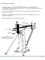
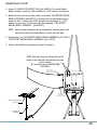
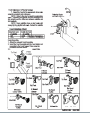
1. Attach 3.8m OFFSET AZ LOCK DOWN ASSEMBLY (PT# 238304) and LOCKDOWN PLATE
(pt# 238304-04) to Kingpost assembly using (4) 1/2nc X 2-1/4 botls and matching washers and nuts.
Leave hardware lose at this time.
2. Slide AZ LOCK DOWN ROD (pt# 238303) thru tube on lock down plate as pictured below. Leave
hardware lose at this time.
3. Attach yoke end of AZ LOCK DOWN ROD to yoke using 3/4” x 2.00” shoulder bolt and 5/8” nut
washers as pictured below.
4. Tighten all hardware once proper AZ angle has been set.
NOTE:
All hardware mentioned above
can be found in hardware bag
AZ LOCK DOWN ROD
(pt# 238303)
OFFSET AZ LOCK DOWN ASSEMBLY (PT#
238304)
LOCKDOWN PLATE
(pt# 238304-04)
Az Lockdown Assembly

8
www.cobham.com/patriot
8
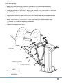
Hub Assembly
1. Place the Hub onto the A-frame using the pre-installed shoulder bolt hardware as shown.
2. Connect the Fixed or Motorized accessories per the attached Appendixs (Fixed shown)
For Fixed Mount Option- See Appendix B.
For Motorized Mount Option- See Appendix C
1. Attach ASSY,3.8M OFFSET KP ELEV.ROD (pt#238302) to yoke pick up detail using
3/4”X 2.00” shoulder bolt, 5/8 nut and washer.
2. Place 3.8M OFFSET KP ELEV.PIVOT BLOCK (pt# 238003) on to 3.8M OFFSET KP ELEV.ROD
(pt#238302) as pictured below. (Leave THIS hardware loose at this time)
2. Place the HUB ASSEMBLY (pt# 238214) on to the A-frame using the pre-installed shoulder
bolt hardware as shown.
3. Attach 3.8M OFFSET KP ELEV.PIVOT BLOCK (pt# 238003) to HUB ASSEMBLY using
(2) 3/4nc X 1-1/2 bolts and matching lock washers.
4. Tighten all hardware at this time.
NOTE:
All hardware mentioned above
can be found in hardware bag
#3HP38013.
3.8M OFFSET KP ELEV.PIVOT
BLOCK (pt# 238003)
3.8M OFFSET KP ELEV.ROD
(pt#238302)
HUB ASSEMBLY
(238214)
Hub Assembly

9
www.cobham.com/patriot
1. Install TUBE,3.8M OFFSET FEED SUPPORTS (pt# 238993) using (4) 1/2nc x 7.00” bolts, matching
washers and (4) FEED BOOM SHIMS (pt# 224132).
2. Tighten all Feed Support hardware.
Feed Boom Install
FEED BOOM SHIMS
(PT#224132)
TUBE,3.8M OFFSET FEED
SUPPORTS (pt# 238993)
This hole, closest
to the edge, up.
Feed Plate Assembly Install
1. Install 3.8M OFFSET FEED PLATE ASSEMBLY
(pt# 238996) using (4) 3/8nc x 3.00” bolts,
washers and nuts.
NOTE:
All hardware mentioned above can
be found in hardware bag #3HP38016.
NOTE:
Make sure that feed booms
are placed as pictured below
with feed plate mounting
holes up.

10
www.cobham.com/patriot
Apply wax here
to aid in sliding
radial beams in to hub
Apply wax here
to aid in sliding
radial beams in to hub
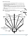
1. Fasten (4) ANGLE,3.8M OFFSET HUB (pt# 238214-12) to each Radial
Beam as shown, using (4) 3/8in shoulder (1) 5/16” washer, and nut per.
2. Adjust the Hub into the position shown, and select 3.8M OFFSET RADIAL
BEAM C ASSEMBLY (pt#238213), and place into the outermost location
inside the Hub. Fasten using 3/8in shoulder bolt hardware, (1) 5/16”
washer, nut per lose. Do the same with the opposing 3.8M OFFSET
RADIAL BEAM C ASSEMBLY (pt#238213).
NOTE: Hard to reach hardware can be accessed by reaching inside and
around the end of the Radial Beam to reach the back side.
3. Repeat step 2 for 3.8M OFFSET RADIAL BEAM B ASSEMBLY (pt# 238211)
3.8M OFFSET RADIAL BEAM A ASSEMBLY (pt# 238210)
4. Tighten all Radial Beam hardware in steps 1 through 3.
ANGLE,3.8M OFFSET HUB
(238214-12)
RADIAL BEAM
ASSEMBLY
NOTE: Shoulder bolts are fastened from the
inside of the Hub with the washers and nuts
on the outside.
All hardware can be found in bag
#3HP38011
Radial Beam Install

11
www.cobham.com/patriot
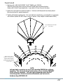
1. Pre-assemble all (20) BRKT.,3.8M OFFSET BACK SUPPORT to the Radial Beams using
1/2x1-1/4” bolt, 2-washers, 1-nut. Leave loose.
2. Attach 3.8M OFFSET 65” BACK SUPPORT L (pt# 238224) and 3.8M OFFSET 90” BACK
SUPPORT (pt# 238223)
3. Starting in the middle and working outward attach (6) ANGLE,3.8M 32” BACK SUPPORT
(pt# 238220) and (4)ANGLE,3.8M 45”BACK SUPPORT using 1/2x1-1/4” bolt, 2-washers,
1-nut.
4. Attach (2)ASSY,3.8M OFFSET 90” BACK SUPPORT (pt# 238223) to the Hub and Radial
Beams as shown.
NOTE: Leave all Frame hardware loose at this time.
NOTE: Assure that all supports angles and frame angles are parallel to
to face of the Hub.
238223
ASSY,3.8M OFFSET 90”
BACK SUPPORT
238223
ASSY,3.8M OFFSET 90”
BACK SUPPORT
238220
ANGLE,3.8M 32” BACK
SUPPORT
238220
ANGLE,3.8M 32” BACK
SUPPORT
238220
ANGLE,3.8M 32” BACK
SUPPORT
238220
ANGLE,3.8M 32” BACK
SUPPORT
238219
ANGLE,3.8M 45”BACK
SUPPORT
238219
ANGLE,3.8M 45”BACK
SUPPORT
238224
ASSY,3.8M OFFSET 65”
BACK SUPPORT L
238225
ASSY,3.8M OFFSET 65”
BACK SUPPORT R
238222
BRKT.,3.8M OFFSET
BACK SUPPORT
Back Structure Install
NOTE:
All hardware mentioned above
can be found in hardware bag
#3HP38011-03

12
www.cobham.com/patriot
1 Starting with ASSY,3.8M OFFSET C-LEFT PANEL (pt# 238208)
Place the panel into place onto the left-most radial ream as pictured below
Fasten with 1/4x1/2 truss head bolts. Leave bolts 1/2 turn loose at this time.
2 Fasten the next panel as mentioned above. Continue untill all panels have been placed.
(See inset picture for panel placement)
3 Tighten all hardware at this time. See note bellow for tightening procedure(If you must step
into reector please DO NOT step in center of panels. Keep weight in radial beams ONLY)
NOTE:
Left and right orentation are as you are standing BEHIND the reector
assembly. The above drawing is pictured as you are standing INFRONT
of the reector assembly. Left and right designated panels are NOT
interchangeable. All above mentioned hardware can be found in
hardware bag 3HP38011-01
ASSY,3.8M OFFSET C-LEFT PANEL
(pt# 238208)
Panel Install
Tighten rst two rows of
hardware on each panel start-
ing here. Then proceed to
next two rows on each panel.
Continue this pattern untill all
screws are tight.

13
www.cobham.com/patriot
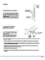
1. Attach Kurfng Segiments to outter most part of panels as pictured below using
same 1/4-20 screws used on panels
2. When all panel, kurfng and hardware is in place tighten all panel and back
structure angle bolts starting near the hub and working outward.
ASSEM, CURFING
46.79” “A”
(238911)
ASSEM, CURFING 57.00”
“C”
(238912)
ASSEM, CURFING
42.68” “B”
(238910)
Kurng Install

14
www.cobham.com/patriot
16
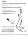
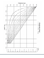
Antenna Pointing
NOTE: The Reflector contains a 23 degree offset look angle. Therefore, when the face of the reflector looks perpendicular
to the ground, the antenna is actually looking 23 degrees in elevation.
The antenna look angle is actually the top side of the Feed Support Plates as shown below.
FOR FIXED MOUNT POINTING-
.
1. Adjust the reflector up or down in elevation by turning the two 2” hex nuts on the Elevation Rod Assembly until the
desired elevation is measured (taking Elevation angle measurement from the Feed Support Arms).
4. Patriot recommends the use of cross pol nulling using a spec-
trum analyzer during TX/RX installations. After tightening the
azimuth and elevation hardware, peak the co-pol signal using
the spectrum analyzer. Then rotate the feed assemble roughly
90 degrees to obtain a cross pol null. Fine tune the null. The
scale on the feed horn can be used with the tick mark on feed
holder top or the seam between feed holder top and bottom. The
tick mark and seam are 90 deg. apart.Note that changes may be
necessary to the resolution and video bandwidth to bring the
signal above the noise floor. Note the angle of optimum cross
pol null. Rotate the feed back exactly 90 degrees and tighten the
feed clamp.
2. Azimuth Adjustment: With the electronics set to acquire the satellite, use the double-nut threaded adjustment on the
Azimuth Rod.
NOTE: If signal is not found on first pass of Azimuth, adjust elevation up
or down in 2 deg increments until signal is found.
3. Peak the satellite signal by fine adjustments made in both azimuth
and elevation until the optimum signal is achieved.
Note: Adjust, tighten, recheck until optimum signal is reached in
both Azimuth and Elevation.
Inclinometer
Focal
Axis

15
www.cobham.com/patriot

16
www.cobham.com/patriot
150
SQ
18
2
" MAX
A
ANCHOR STUDS & HDWE
INCLUDED w/ANTENNA.
SECURE USING CHEMICAL
ADHESIVE; HILTI P/N 283548
RECOMMENDED.
2
9.50
CENT
TYP
66
12.6
APPROX TYP
66
28.4
APPROX
1
(FRONT OF ANTENNA)
(2X) Ø1-1/16 DRILL ~ 8" DP,
TRANSFER LOCATION AT ASS'Y
FROM SUPPORT STRUTS.
ADD (4) 112" RE-BARS
(2 EACH WAY) AS SHOWN
TO TOP LAYER
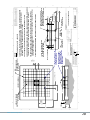
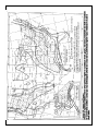
NOTES:
1. SOIL BEARING CAPACITY = 2000 PSF
2. CONCRETE, 3000 PSI AT 28 DAYS, POURED & VIBRATED AGAINST UNDISTURBED
SOIL. ALLOW (24) HOURS FOR CONCRETE TO SET BEFORE INSTALLATION OF
ANTENNA. ESTIMATED CONCRETE USAGE = 8.7 YARDS
3. USE #5 (Ø5/8) RE-BAR IN CONCRETE PAD. ESTIMATED USAGE = 478 FT.
4. ANCHOR RODS, WASHERS, AND NUTS SHALL BE GRADE 5 OR BETTER, GALVANIZED.
(HDWE. & TEMPLATE KIT IS AVAILABLE FROM PATRIOT ANTENNA SYSTEMS).
5. WHEN THE FROST LINE IS BELOW (10) INCHES THE BASE SLAB/SOIL REQUIRES
SPECIAL DESIGN CONSIDERATIONS TO PREVENT HEAVING; CONSULT A LOCAL
LICENSED CIVIL ENGINEER.
6. LIGHTNING AND GROUNDING PROVISIONS PER LOCAL REGULATIONS.
(2X)
120" SQ. RE-BAR GRID
(11) ROWS SYMMETRICAL
ON 12" CENTERS
4-1/2" MIN
4.50
(SET RODS)
8.00
7
" REBAR
GRID SPACING
DETAIL A
SCALE 1 : 12
TOP OF CONCRETE
18.0 SQ HOLE PATTERN TEMPLATE
(TO BE REMOVED PRIOR TO
MOUNTING KING POST)
(4X)
10 GA (.1345)
STEEL STRAPS
REST RE-BAR
GRID ON STRAPS
(4X) 1-1/2-6 UNC-2B x 18" LG
ANCHOR RODS w/NUTS & WASHERS
(ENSURE RODS ARE VERTICAL)
REF. PATRIOT KIT #PRT-BTK380OFFSET
08FEB08
1
DIM ADDED
EMJ
2
EMJ
WAS HILTLI P/N 00333178
05MAY08
D
C
B
A
A
B
C
D
1
2
3
4
5
6
7
8
8
7
6
5
4
3
2
1
THE INFORMATION CONTAINED IN THIS
DRAWING IS THE SOLE PROPERTY OF
PATRIOT ANTENNA SYSTEMS. ANY
REPRODUCTION IN PART OR AS A WHOLE
WITHOUT THE WRITTEN PERMISSION OF
PATRIOT ANTENNA SYSTEMS IS PROHIBITED.
PROPRIETARY AND CONFIDENTIAL
FRACTIONAL
1/16"
ANGULAR:
1
X
.062"
XX
.031"
XXX
.015"
XXXX
.005"
DRAWN BY:
ENG APPR.
NOTES:
DATE
NAME
TITLE:
SIZE
B
DWG. NO.
REV
SCALE: 1:24
UNLESS OTHERWISE SPECIFIED:
SHEET 1 OF 1
REVISIONS
DESCRIPTION
REV.
DATE
APPROVED
ZONE
EMJ
22JAN08
KS
JAN08
001
2FD380V0001
3.8m OFFSET FOUNDATION
MATERIAL:
1) PAS ANCHOR KIT #PRT-BTK380OFFSET
Tolerances
:
DIMENSIONS ARE IN INCHES:
CORNERS ARE AT 90

17
www.cobham.com/patriot
1. Assemble the Elevation Jack assembly to
the Hub assy as shown using 2- 3/4x2-1/2”
shoulder bolts, 2- 3/4” washers(bolt side), 2-
5/8” washers (nut side), and 2- 5/8” nylok
nuts.
2. Assemble the Jack extension rod to the
Yoke assy using 1- 3.4x4” bolt, 2 washers,
and nylok nut.
Mototized Mount Option Assembly
Appendix C
3. Mount the Azimuth GearDrive to the
KingPost Mast assembly using 4- 3/8x1-1/2”
bolts and washers.
4. Assemble the keyed drive sprocket, key
and guide bushing to the drive shapft as
shown. Leave loose to adjust height later.
Drive Gear
238310
Actuator Adaptor
Plate
238306 (2)
Appendix B

18
www.cobham.com/patriot
5. Place the D-Ring assy onto the mast
and yoke assy’s as shown. Use the
“Resolver Shoulder Bolt assy” for the D-
ring-Yoke assy pivot.
6. Assemble the D-Ring to the Yoke
using 2- 1/2x1-1/2” Flat Socket Head
bolts, 2 washers, and 2 nylok nuts.
Mototized Mount Option Assembly
Appendix C
(continued)
1/2x1-1/2”
Counter Sunk
Socket Head
Bolt
D-Ring
attachment
plate
7. Replace the right Hub connection shoulder bolt
with a “Resolver Shoulder Bolt assy”.
8. Wrap the chain assyin place around the D-Ring
and drive sprocket attaching the chain tensioner
blocks to the yoke with 2- 5/8x1-1/2” NF bolts and
washers,
NOTE: Apply lock-tite thread compound to the
threads of these fasteners.
9. Line up the 2 Idler sprockets and Idler plate.
Using 4- 5/8x4” bolts, 2 washers, and nylok nuts
assemble the Idler plate as shown.
10. Adjust the chain tension purposely leaving a
small amount of slack. Each adjuster bolt and
chain tensioner block should have an equal gap to
one another.
Spacer Tubes
20000054 (2)
Idler plate
238309
Chain
Tensioner
Bolts
Idler gear
238311 (2)
Elevation encoder
bolt assem
238243Azmuth encoder
bolt assem
238234
Appendix B

19
www.cobham.com/patriot
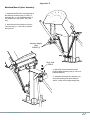
11. Mount Elevation Limit Switch and bracket, as shown, to yoke cross tube
12. Mount Azmuth Limit Switch to bracket as done in previous step. Mount bracket to King Post MAst as
shown.
Mototized Mount Option Assembly
Appendix C
(continued)
Trip Blocks, 238239 (4)
Approx. Range
of Motion
Yoke Cross Tube
Kingpost Mast
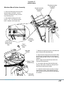
13 Assemble the Adjustable Limit stop plates to the
spacer blocks and rough adjust a range of motion as shown.
Spacer Block
238241
Spacer Block,238241, mounted
to underside of Hub
14. Connect the wiring per instrucitons of the selected controller unit.
NOTE: The Azimuth range of motion can be adjusted to any desired
range within its’ 180deg capability. Just be certain to trip the switch
before the Yoke bumps the Mast assembly.
1/4-20x .75”
Hardware
Hub
Limit Switch Bracket
20000038 (2)
Limit Switch Cut
off Plate
20000039 (2)
Adaptor Bracket
238242
Appendix B

20
www.cobham.com/patriot
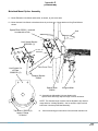
15. Assemble the Drive motors to the Elevation acutator and the Azimuth Gearbox.
Mototized Mount Option Assembly
Appendix C
(continued)
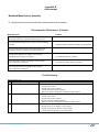
Recommended Maintenance Schedule
Maintenance Item Comment
Check Azimuth gearbox oil level. Oil level should be even
with fill plug. Add oil as required to maintain proper level
Check Azimuth chain and sprockets for dirt. Clean and lubricate
as needed. Lubricate with good commercial quality spray lubricant
Check Elevation gearbox oil level. Oil level should be even
with fill plug. Add oil as required to maintain proper level.
Check Elevation Jack boot for damage or deterioration.
Clean dirt and oil from boot as required. Use soap and water for cleaning
Check cables and connectors for damage or deterioration.
Clean as required to prolong life. Use electrical contact cleaner as required
Check wiring for strain relief, damage or deterioration.
Clean as required to prolong life.
Troubleshooting
Troubleshooting Tips
Item Symptom Recommended Action
1 Antenna will not drive. xCheck for mechanical interference
xCheck power source
xCheck fuses in drive cabinet
xCheck limit switch status/operation
xRefer to controller maintenance manual for further options
2 Feed polarization will not drive. xCheck for mechanical interference
xCheck power source
xCheck fuses in drive cabinet
xCheck limit switch status/operation
xRefer to controller maintenance manual for further options
3 Low signal strength xCheck pointing of antenna and re-peak as required if mis-pointed
xCheck feed assy for damage or water ingress
xCheck waveguide for damage or water ingress
xCheck cables for damage or poor connections
Appendix B
Page is loading ...
Page is loading ...
Page is loading ...
Page is loading ...
-
 1
1
-
 2
2
-
 3
3
-
 4
4
-
 5
5
-
 6
6
-
 7
7
-
 8
8
-
 9
9
-
 10
10
-
 11
11
-
 12
12
-
 13
13
-
 14
14
-
 15
15
-
 16
16
-
 17
17
-
 18
18
-
 19
19
-
 20
20
-
 21
21
-
 22
22
-
 23
23
-
 24
24


COBHAM 3.8m Offset Antenna Installation guide
- Type
- Installation guide
COBHAM 3.8m Offset Antenna is a high-quality device designed for receiving and transmitting signals. It is commonly used in satellite communication systems and can be employed in various applications, such as:
- Television and radio broadcasting
- Data transmission
- Internet access
- Military and government communications The antenna features a robust construction and is built to withstand harsh weather conditions, making it suitable for outdoor installations. Its 3.
Ask a question and I''ll find the answer in the document
Finding information in a document is now easier with AI
Related papers
-
COBHAM BSF0060 User Handbook Manual
-
-
-
-
-
-
-
-
-
Other documents
-
König SAT-BEG42 Datasheet
-
-
 Patriot Products Patriot 3.8m Commercial Antenna King Post Mount User manual
-
Ubiquiti Networks SWX-LBE5ACG2 User manual
-
Blue Ox BRK2016 User guide
-
EZ Tube EZTUBE4 Installation guide
-
Hygain GRK-88 User manual
-
 Swurfer SWBKT Operating instructions
-
 Andrew 123 1.2 Meter Class I Assembly Instructions Manual
-
 Arrow Antenna GP 126 User manual


