Page is loading ...

Cobham Wireless – Coverage
Date: 17-Jan-16
www.cobham.com/wireless
Doc. No. 00060CDUM Rev. 1.1 Page | I
The most important thing we build is trust
D-MBR 3707 3708
Class A PS NFPA Signal Booster
The future of in-building coverage
User Manual – 00068CDUM Rev. 1.2
This manual is relevant for 700/800 MHz Digital Multi-Channel Class A RF Signal
Booster
D-MBR 3707-3708 PS NFPA Booster
D-MBR 3707-3708 AC feeder and battery charger

D-MBR 3707-3708 PS NFPA CLASS A SIGNAL BOOSTER
PRODUCT DESCRIPTION AND USER’S MANUAL
www.cobham.com/wireless
Date: 17-Jan-16
Cobham Wireless – Coverage
Page | II Rev. 1.1 Doc. No.00060CDUM
Copyright © 2016 Axell Wireless Limited trading as Cobham Wireless
All rights reserved.
No part of this document may be copied, distributed, transmitted, transcribed, stored in a retrieval system, or
translated into any human or computer language without the prior written permission of Axell Wireless Limited
trading as Cobham Wireless.
The manufacturer has made every effort to ensure that the instructions contained in this document are
adequate and free of errors and omissions. The manufacturer will, if necessary, explain issues which may not be
covered by this document. The manufacturer's liability for any errors in the document is limited to the correction
of errors and the aforementioned advisory services.
This document has been prepared to be used by professional and properly trained personnel, and the customer
assumes full responsibility when using them. The manufacturer welcomes customer comments as part of the
process of continual development and improvement of the documentation in the best way possible from the
user's viewpoint. Please submit your comments to the nearest Cobham Wireless sales representative.
Contact Information
Headquarters Axell Wireless trading as Cobham Wireless
Aerial House, Asheridge Road
Chesham, Buckinghamshire
HP5 2QD, United Kingdom
Tel: +44 1494 777000
Fax: +44 1494 777002
Commercial inquiries
cw.coverage@cobham.com
Website
www.cobham.com/wireless
Support issues
cw.support@cobham.com
Technical Support Line, English speaking +44 1494 777 747
About This Manual
This Product Manual provides the following information:
• Description of the Repeater unit
• Procedures for setup, configuration and checking the proper operation of the unit
• Maintenance and troubleshooting procedures
For whom it is intended
This Product Manual is intended for experienced technicians and engineers. It is assumed that the customers
installing, operating, and maintaining Cobham Wireless Repeaters are familiar with the basic functionality of
Repeaters.
Notice
Confidential - Authorized Customer Use
This document may be used in its complete form only and is solely for the use of Cobham Wireless employees
and authorized Cobham Wireless channels or customers. The material herein is proprietary to Cobham Wireless.
Any unauthorized reproduction, use or disclosure of any part thereof is strictly prohibited.
All trademarks and registered trademarks are the property of their respective owners.

D-MBR 3707-3708 PS NFPA CLASS A SIGNAL BOOSTER
PRODUCT DESCRIPTION AND USER’S MANUAL
Cobham Wireless – Coverage
Date: 17-Jan-16
www.cobham.com/wireless
Doc. No.00060CDUM Rev. 1.1 Page | III
Disclaimer of Liability
Contents herein are current as of the date of publication. Cobham Wireless reserves the right to change the
contents without prior notice. The information furnished by Cobham Wireless in this document is believed to be
accurate and reliable. However, Cobham Wireless assumes no responsibility for its use. In no event shall
Cobham Wireless be liable for any damage resulting from loss of data, loss of use, or loss of profits and Cobham
Wireless further disclaims any and all liability for indirect, incidental, special, consequential or other similes
damages. This disclaimer of liability applies to all products, publications and services during and after the
warranty period.
Safety Instructions and Warnings
Throughout this manual, important safety warnings and admonishments are included to warn of possible
hazards to persons or equipment. A safety warning identifies a possible hazard and then describes what may
happen if the hazard is not avoided. The safety warnings – in the form of Dangers, Warnings and Cautions must
be followed at all times. These warnings are flagged by the use of a warning icon, usually the triangular alert
icon seen below. The exclamation point within the triangular alert icon is intended to warn the operator or
service personnel of operation and maintenance from factors relating to the product and its operating
environment, which could pose a safety hazard.
Guarantees
All antennas must be installed with lightning protection. Damage to power modules, as a result of lightning are
not covered by the warranty.
Switching on AC or DC power prior to the connection of antenna cables is regarded as faulty installation
procedure and therefore not covered by the Cobham Wireless warranty.
Repeater enclosures should be closed using the two screws. The screws must be fully tightened. Failure to do so
may affect the IP65 compliancy and therefore any warranty.
Exclusive Remedies
The remedies provided herein are the Buyer’s sole and exclusive remedies. Cobham Wireless shall not be viable
for any direct, incidental, or consequential damages, whether based on contract, tort, or any legal theory.
Unauthorized Changes to Equipment
Changes or Modifications not expressly approved by the manufacturer responsible for compliance could void the
user’s authority to operate the equipment

D-MBR 3707-3708 PS NFPA CLASS A SIGNAL BOOSTER
PRODUCT DESCRIPTION AND USER’S MANUAL
www.cobham.com/wireless
Date: 17-Jan-16
Cobham Wireless – Coverage
Page | IV Rev. 1.1 Doc. No.00060CDUM
General Safety Warnings Concerning Use of System
Always observe standard safety precautions during installation, operation and maintenance of this
product.
Caution labels!
Throughout this manual, there are "Caution" warnings. "Caution" calls attention to
a procedure or practice, which, if ignored, may result in injury or damage to the
system, system component or even the user. Do not perform any procedure
preceded by a "Caution" until the described conditions are fully understood and
met.
Danger: Electrical Shock
This equipment can either be installed indoors or outdoors. When installed
outdoors - wet conditions increase the potential for receiving an electric shock
when installing or using electrically powered equipment. To prevent electrical shock
when installing or modifying the system power wiring, disconnect the wiring at the
power source before working with un insulated wires or terminals.
Caution: Safety to
personnel
Before installing or replacing any of the equipment, the entire manual should be
read and understood.
The user needs to supply the appropriate AC or DC power to the booster. Incorrect
power settings can damage the Booster and may cause injury to the user.
Please be aware that the equipment may, during certain conditions become very
warm and can cause minor injuries if handled without any protection, such as
gloves.
Caution: Safety to
equipment
When installing, replacing or using this product, observe all safety precautions
during handling and operation. Failure to comply with the following general safety
precautions and with specific precautions described elsewhere in this manual
violates the safety standards of the design, manufacture, and intended use of this
product.
Cobham Wireless assumes no liability for the customer's failure to comply with
these precautions. This entire manual should be read and understood before
operating or maintaining the booster.
Warning: Restricted
Access Location
Access to the unit installation location is restricted to SERVICE PERSONNEL who
have been instructed on the restrictions and the required precautions to be taken.

D-MBR 3707-3708 PS NFPA CLASS A SIGNAL BOOSTER
PRODUCT DESCRIPTION AND USER’S MANUAL
Cobham Wireless – Coverage
Date: 17-Jan-16
www.cobham.com/wireless
Doc. No.00060CDUM Rev. 1.1 Page | V
Compliance with FCC
WARNING!!! This repeater must be operated as a Part 90 Class A repeater.
The installation procedure must result in the signal booster complying with FCC
requirements 90.219(d). In order to meet FCC requirements 90.219(d), it may be
necessary for the installer to reduce the UL and/or DL output power for certain
installations.
FCC Part 15
This device complies with part 15 of the FCC Rules. Operation is subject to the following two conditions:
1. This device may not cause harmful interference, and
2. This device must accept any interference received, including interference that may cause undesired operation.
This equipment has been tested and found to comply with the limits for a Class A digital device, pursuant to
part 15 of the FCC Rules. These limits are designed to provide reasonable protection against harmful
interference when the equipment is operated in a commercial environment. This equipment generates, uses,
and can radiate radio frequency energy and, if not installed and used in accordance with the instruction manual,
may cause harmful interference to radio communications. Operation of this equipment in a residential area is
likely to cause harmful interference in which case the user will be required to correct the interference at their
own expense.
Only for in-building applications
One must be aware that FCC regulation mandate that this repeater is to be used
only
for in-building applications
and thus feed passive or active DAS (Distributed Antenna Systems) accordingly.
FCC RF Exposure Limits
This unit complies with FCC RF exposure limits for an uncontrolled environment. This equipment can only be
installed in in-building applications, driving passive or active DAS systems. All antennas must be operated at a
minimum distance of 28 cm between the radiator and any person’s body.
Antenna Installation
Installation of an antenna must comply with the FCC RF exposure requirements. The antenna used for this
transmitter must be mounted on outdoor or indoor permanent structures. The maximum antenna gain for indoor
operation is 2.2 dBi and for the external antenna is 7dBi. Cable loss of at least 2dB is taken into account for all
cases.Antennas having a gain greater than these are strictly prohibited for use with this device. In indoor
applications the antenna must be installed at a minimum separation distance of 28cm from all nearby persons.

D-MBR 3707-3708 PS NFPA CLASS A SIGNAL BOOSTER
PRODUCT DESCRIPTION AND USER’S MANUAL
www.cobham.com/wireless
Date: 17-Jan-16
Cobham Wireless – Coverage
Page | VI Rev. 1.1 Doc. No.00060CDUM
Compliance with IC
Under Industry Canada regulations, this radio transmitter may only operate using an antenna of a type and
maximum (or lesser) gain approved for the transmitter by Industry Canada. To reduce potential radio
interference to other users, the antenna type and its gain should be so chosen that the equivalent isotropically
radiated power (e.i.r.p.) is not more than that necessary for successful communication.
The Manufacturer's rated output power of this equipment is for single carrier operation. For situations when
multiple carrier signals are present, the rating would have to be reduced by 3.5 dB, especially where the output
signal is re-radiated and can cause interference to adjacent band users. This power reduction is to be by means
of input power or gain reduction and not by an attenuator at the output of the device.
This equipment complies with IC RSS-102 radiation exposure limits set forth for an uncontrolled environment.
This equipment should be installed and operated with minimum distance 28 cm between the antenna and your
body,
Conformément à la réglementation d'Industrie Canada, le présent émetteur radio peut fonctionner avec une
antenne d'un type et d'un gain maximal (ou inférieur) approuvé pour
l'émetteur par Industrie Canada. Dans le
but de réduire les risques de brouillage radioélectrique à l'intention des autres utilisateurs, il faut choisir le type
d'antenne et son gain de sorte que la puissance isotrope rayonnée équivalente (p.i.r.e.) ne dépasse pas
l'intensité nécessaire à l'établissement d'une communication satisfaisante.
La puissance de sortie nominale indiquée par le fabricant pour cet appareil concerne son fonctionnement avec
porteuse unique. Pour des appareils avec porteuses multiples, on doit réduire la valeur nominale de 3.5 dB,
surtout si le signal de sortie est retransmis et qu'il peut causer du brouillage aux utilisateurs de bandes
adjacentes. Une telle réduction doit porter sur la puissance d'entrée ou sur le gain, et ne doit pas se faire au
moyen d'un atténuateur raccordé à la sortie du dispositif.
Cet appareil est conforme aux limitations de la norme IC RSS-102 concernant l’exposition aux radiations dans un
environnement non contrôlé. Cet appareil doit être installé et utilisé avec une distance minimale de 28 cm entre
l’antenne et le corps de l’utilisateur.

Cobham Wireless – Coverage
Date: 17-Jan-16
www.cobham.com/wireless
Doc. No. 00060CDUM Rev. 1.1 Page | VII
Table of Contents
1 INTRODUCTION ............................................................................................................ 1
1.1 Main Features......................................................................................................... 1
1.2 Booster Ordering Information ................................................................................. 2
1.3 Architecture ........................................................................................................... 2
1.4 Smart-ALC Function ............................................................................................... 3
1.5 Power Feeder and Battery Charger ......................................................................... 3
1.6 Booster Interfaces .................................................................................................. 4
1.7 Functional Description ........................................................................................... 5
2 BOOSTER PRE-INSTALLATION REQUIREMENTS AND GUIDELINES .............................. 6
2.1 Donor Antenna Considerations ............................................................................... 6
2.1.1 Required Antenna Information ............................................................................6
2.1.2 Donor Antenna specifications .............................................................................6
2.1.3 Installation Criteria .............................................................................................6
2.2 Service Antenna Considerations ............................................................................. 7
2.2.1 Required Information .........................................................................................7
2.2.2 Indoor Installations .............................................................................................7
2.2.3 Outdoor Installations ..........................................................................................8
2.3 Required BTS Information .................................................................................... 10
2.4 Selecting the Booster Location ............................................................................. 10
2.4.1 Installation Location Criteria and Environment ................................................... 10
2.4.2 Verifying the Link between the BTS and the Signal Booster ................................ 11
2.5 RF Cable Installation Guidelines ........................................................................... 12
3 BOOSTER MOUNTING AND INSTALLATION ................................................................ 13
3.1 Booster Installation Overview ............................................................................... 13
3.2 Booster Unpacking and Package Contents ........................................................... 14
3.3 Mounting the System ............................................................................................ 15
3.3.1 Location Criteria .............................................................................................. 15
3.3.2 Rack Mount Installation .................................................................................... 16
3.3.3 Wallmount Installation ...................................................................................... 17
3.4 Booster Connections ............................................................................................ 23
3.4.1 Grounding ....................................................................................................... 23
3.4.2 Antenna Connections and Guidelines................................................................ 24
3.4.3 Booster Dry-Contact Alarm Connections ........................................................... 25
3.4.4 Connecting Power and Power-Up ..................................................................... 27
4 BATTERY CHARGER DESCRIPTION AND INSTALLATION ............................................ 28
4.1 Charger Ordering Information ............................................................................... 28
4.2 Charger Architecture ............................................................................................ 29
4.3 Charger Interfaces ................................................................................................ 30
4.4 Charger Installation Procedure ............................................................................. 31
4.4.1 Charger Installation Location ............................................................................ 32
4.4.2 Charger Unpacking and Package Contents ....................................................... 32
4.4.3 Charger Mounting Procedure ............................................................................ 33
4.4.4 Charger Grounding .......................................................................................... 33
4.4.5 Charger Alarm Connections ............................................................................. 34
4.4.6 Charger to Booster, Battery and AC Feed Connections ...................................... 36

D-MBR 3707-3708 PS NFPA CLASS A SIGNAL BOOSTER
PRODUCT DESCRIPTION AND USER’S MANUAL
www.cobham.com/wireless
Date: 17-Jan-16
Cobham Wireless – Coverage
Page | VIII Rev. 1.1 Doc. No.00060CDUM
5 SETUP AND COMMISSIONING ..................................................................................... 38
5.1 Overview of the Commissioning Procedure ........................................................... 38
5.2 Opening a Session to the Booster and Navigating the GUI ..................................... 39
5.2.1 Open a First Time Local Web Session to the Booster ......................................... 39
5.2.2 Navigating the Web GUI Application ................................................................. 40
5.3 RF Parameters and Channel Configuration ............................................................ 43
5.4 Date and Time Settings ......................................................................................... 47
5.5 External Alarms Configuration .............................................................................. 48
5.6 IP Address and SNMP Notifications ....................................................................... 49
5.6.1 Configuring the IP Address ............................................................................... 50
5.6.2 SNMP Trap Configuration ................................................................................ 51
5.7 Changing Password .............................................................................................. 52
6 ADMINISTRATIVE OPERATIONS .................................................................................. 53
6.1 User Management ................................................................................................. 53
6.1.1 User Levels ..................................................................................................... 53
6.1.2 Viewing the List of Defined Users...................................................................... 53
6.1.3 Adding Users ................................................................................................... 54
6.1.4 Editing a User .................................................................................................. 54
6.1.5 Deleting a User ................................................................................................ 54
6.2 Viewing General Information ................................................................................. 55
6.2.1 Viewing Booster Level Information .................................................................... 55
6.2.2 Viewing Band Level Info ................................................................................... 56
6.3 Band-Level Configuration Backup/Restore ............................................................ 57
6.3.1 The Backup/Restore Tab .................................................................................. 57
6.3.2 Backup Band Configuration .............................................................................. 58
6.3.3 Restoring Band Configuration ........................................................................... 58
6.3.4 Uploading Band Configuration File .................................................................... 59
6.3.5 Saving Configuration File to Computer .............................................................. 59
6.4 CMU Software Upgrade ......................................................................................... 60
7 MONITORING AND TROUBLESHOOTING ..................................................................... 61
7.1 LED Troubleshooting ............................................................................................ 61
7.2 Booster Level Alarms Log ..................................................................................... 62
7.3 Viewing Activated Alarms...................................................................................... 63
7.4 Band-Level Alarms and Troubleshooting ............................................................... 64
7.5 Modifying Alarm Severities .................................................................................... 66
Appendix A – Booster and Charger Specifications ........................................................ 67

D-MBR 3707-3708 PS NFPA Class A Signal Booster
PRODUCT DESCRIPTION AND USER’S MANUAL
Cobham Wireless – Coverage
Date: 17-Jan-16
www.cobham.com/wireless
Doc. No.00060CDUM Rev. 1.1 Page | 1
1 INTRODUCTION
D-MBR 3707-3708 PS NFPA (Digital Multi Band Repeater for Public Safety) is a Class A Digital Multi-
Channel Signal Booster (DCSB). It features an array of up to 12 DSP based, software-controlled,
variable bandwidth filters (up to 75Khz) per band , that are user-programmable across the 700 and
800 MHz bands.
D-MBR 3707-3708 PS NFPA supports all public safety technologies. For each filter, the user can
specify the start and stop frequencies to reduce the installation time of the signal booster and enable
a very wide range of filters selection.
Every parameter of D-MBR 3707-3708 PS NFPA, including filter tuning and selection, can be
controlled via web based management. The patented Cobham Wireless’ digital RF filter enables
simple initial setup for any channel plan and if necessary, allows some basic reconfiguration due to
re-banding.
The SALC -Smart ALC algorithm will reduce the gain to protect the signal booster from oscillation.
When the gain cannot be reduced anymore a shut-down mechanism will be triggered.
The signal booster protects against degradation of the system’s sensitivity and coverage. This is
implemented by the inbuilt AGC per-channel (filter) feature, which permits equalization of the
channel levels for uniform coverage.
This product meets the rigid requirements as defined by the NFPA and International Fire Code
developmental organizations. The amplifier is painted a Fire Life Safety Red, meets NEMA4
compliance for hose down, and provides all Alarming outputs as defined by NFPA 2010, Chapter 24
including system and antenna failures. The signal booster is a DC fed unit.
An external battery charger unit is available as well. The charger is connected to the AC and includes
a circuit to charge external batteries with all the dry contact alarms as defined in the NFPA standard:
AC failure, Charger failure and Low battery.
1.1 Main Features
• Class A - signal booster for SMR and public safety networks
• Supports APCO 25 phase 1 and 2 for public safety networks
• NFPA 72-2010, Chapter 24 and IFC 510.1 Compliant
• Support of 700MHz D block for LTE network
• Patented DSP filtering™ technology:
• Supports up to 12 independent filters per band
• User programmable bandwidth / frequency
• NEMA4 enclosure
• SALC-Smart ALC mechanism to protect the digital signal booster from oscillation and shutdown
the signal booster when required
• Web based management, SNMP traps

D-MBR 3707-3708 PS NFPA CLASS A SIGNAL BOOSTER
PRODUCT DESCRIPTION AND USER’S MANUAL
www.cobham.com/wireless
Date: 17-Jan-16
Cobham Wireless – Coverage
Page | 2 Rev. 1.1 Doc. No.00060CDUM
1.2 Booster Ordering Information
NOTE: Charger ordering information is provided in section 4.1.
IDENTIFICATION DESCRIPTION PART NUMBER
D-MBR 3707-3708 PS
with NFPA and Red
painted case
Digital Multi Channel Selective Signal Booster
Class A 700/800 MHz 12
filters, 37dBm
composite per band, 95dB gain, DC powering
with NFPA and IFC compliant Alarm Outputs
and red painted case.
D-MBR 3707-3708-PS-
NFPA-DC-CLASS-A
1.3 Architecture
To meet the National Fire Protection Association (NFPA) requirements, power to the Signal booster is
provided via an uninterrupted power source. This can either be a UPS or (if a UPS is not available),
an AC Feeder and Battery Charger (purchased separately).
NOTE: The Power Feeder Battery Charger is described in Chapter - 4).
Alarm connections to the Fire Department Control Box are used to monitor the status of the
uninterrupted power source, Signal Booster and DAS system (antennas).
As an alternative to the
Fire Department Control Box connections, the D-MBR PS NFPA and UPS or
Charger dry contact alarms can be connected to an Automatic Dialer. The AD-2000 Automatic
Voice/Pager Dialer System is recommended.
If the AC power to the UPS fails, the required power is provided by the battery and the AC Power Fail
alarm is activated.
Figure 1-1. D-MBR PS NFPA Architecture

D-MBR 3707-3708 PS NFPA CLASS A SIGNAL BOOSTER
PRODUCT DESCRIPTION AND USER’S MANUAL
Cobham Wireless – Coverage
Date: 17-Jan-16
www.cobham.com/wireless
Doc. No.00060CDUM Rev. 1.1 Page | 3
1.4 Smart-ALC Function
The Signal Booster’s power amplifier includes power-monitoring circuits with Automatic Level Control
(ALC) that prevents excessive output power while maintaining the power amplifier linearity
The Smart Automatic Level Control (Smart-ALC) is an innovative algorithm for automatic Signal
Booster gain adjustment. Combined with advanced control algorithms, SALC is capable of learning
the traffic load characteristics and adjusting the Signal Booster RF Gain to the desired value.
Note: To reset the Signal Booster to its highest set gain value, disconnect the Signal Booster power
cable for several seconds and re-connect.
1.5 Power Feeder and Battery Charger
NOTE: The Power Feeder and Battery Charger is described in Chapter - 4).
For installations where UPS is not available, the AC Feeder and Battery Charger unit can be
purchased (see section
4.1 for ordering information).
The charger is connected directly to the AC inlet and includes a circuit to charge external batteries
(meeting the specifications described in section
4.4.6. The charger also includes the following dry
contact alarms (as defined in the NFPA standard): AC failure, Charger failure and Low battery.
NOTE: BATTERY LOW indication is when battery reaches 70% at current consumption of ~ C/25
Figure 1-2. D-MBR Charger

D-MBR 3707-3708 PS NFPA CLASS A SIGNAL BOOSTER
PRODUCT DESCRIPTION AND USER’S MANUAL
www.cobham.com/wireless
Date: 17-Jan-16
Cobham Wireless – Coverage
Page | 4 Rev. 1.1 Doc. No.00060CDUM
1.6 Booster Interfaces
All booster interfaces are located on the underside as shown below.
WARNING! The signal booster must always be installed vertically and top-down – with
the connectors on the underside for protection (see 3.3.3.4). Horizontal installation on a bench for
long time may cause damage to the signal booster due to over-heating.
Figure 1-3. D-MBR Front Panel
Interface Description
BASE
Donor antenna connections. See section
2.1.
MOBILE
Service antenna connections. See section
2.2.
48 VDC Connection to 48VDC (either from UPS or from the Charger).
ALARMS
Two External (input) and two Output (relay) alarms. See section
3.4.3.
GND LUG
Ground connection. See section
3.4.1.
LED’S Two status LEDs: 700 MHz and 800 MHz bands
Upper LED: UL status (for both bands.
Lower LED: DL status for both bands
Status: Green (OK), Orange (Warning), Red (Fail).
Donor antenna
connection
Service antenna
connection
48V DC power
GND LUG
Dry contact alarms
Ethernet port
Signal Status LEDs

D-MBR 3707-3708 PS NFPA CLASS A SIGNAL BOOSTER
PRODUCT DESCRIPTION AND USER’S MANUAL
Cobham Wireless – Coverage
Date: 17-Jan-16
www.cobham.com/wireless
Doc. No.00060CDUM Rev. 1.1 Page | 5
1.7 Functional Description
In the downlink, the signal from the Donor antenna is filtered to the 700MHz and 800MHz bands,
down converted, filtered according to the user defined (via GUI) channels, down converted and
amplified. The signals are then forwarded to the service antenna. In the uplink, the process is
reversed.
The maximum Analog Gain is 95dB, where Channel Gain between 0dB and 95dB is achieved by
reducing the Digital Gain from the System maximum Analog Gain; therefore, filtering and attenuation
is achieved through Digital Processing.
The block diagram showed in the figure below illustrates the overall functionality of the D-MBR PS
NFPA Signal Boosters and shows the operation flow in the downlink path and the uplink path.
Figure 1-4 Signal Booster - Block Diagram

D-MBR 3707-3708 PS NFPA CLASS A SIGNAL BOOSTER
PRODUCT DESCRIPTION AND USER’S MANUAL
www.cobham.com/wireless
Date: 17-Jan-16
Cobham Wireless – Coverage
Page | 6 Rev. 1.1 Doc. No.00060CDUM
2 BOOSTER PRE-INSTALLATION REQUIREMENTS
AND GUIDELINES
This section describes the pre-installation requirements and guidelines
WARNINGS!!
• The installer is held accountable for implementing the rules required for deployment.
• Good engineering practice must be used to avoid interference.
• Output power should be reduced to solve any IMD interference issues.
2.1 Donor Antenna Considerations
The Base (Donor) antenna is usually installed outdoors and is either a directional antenna such as a
Yagi or a Panel antenna.
2.1.1 Required Antenna Information
You will require the following antenna information:
• Antenna type and characteristics
• Height
• Length and type of coaxial cable required for connecting the Donor antenna to the Signal Booster
and the attenuation.
2.1.2 Donor Antenna specifications
• Yagi type or similar – 10 to 15 dBi gain, very sharp beam pointed to the BTS.
• Cable and jumper loss is at least 2dB.
• The required Base signals should be the dominant signals; at least 6 dB higher power than other
signals.
• Example of antenna's typical specifications:
Gain: 8 dBd (=10.1 dBi)
VSWR: < 1:5:1
Impedance: 50 ohm
2.1.3 Installation Criteria
NOTE: Verify that the antennas meet requirements described in the previous sections..
Installation requirements:
• Select a location for the Donor antenna and verify that there is the signal strength is strong
enough at that location.
• Install the Donor Antenna at the designated height.
• The antenna should point to the direction of the base station for maximum input power.
• Verify that the antenna is in the base stations line of sight (raise the antenna if necessary).
• Install the donor antenna at a higher level (i.e. floor) than the mobile antenna.
• Must be installed at a minimum distance of 1 meter from any personnel within the area.

D-MBR 3707-3708 PS NFPA CLASS A SIGNAL BOOSTER
PRODUCT DESCRIPTION AND USER’S MANUAL
Cobham Wireless – Coverage
Date: 17-Jan-16
www.cobham.com/wireless
Doc. No.00060CDUM Rev. 1.1 Page | 7
2.2 Service Antenna Considerations
The Service antenna type depends on whether the Signal Booster is installed indoors or outdoors.
2.2.1 Required Information
The following antenna requirements, specifications and site considerations should be met.
• Type of installation – indoor or outdoor
• Service area size
• Height at which antenna(s) is/are installed
• Antenna type and characteristics
• Length and type of coaxial cable required for connecting the Service antenna to the Signal
Booster and the attenuation.
2.2.2 Indoor Installations
2.2.2.1 Recommended Antennas
The following describes the requirements for an omni-directional mobile used for indoor applications.
Specifications:
• One or a combination of the following antennas can be used: Ceiling Mount Patch antenna, Wall
Mount Patch antenna, Corner Reflector.
• Omni directional antenna with a 0 to 2 dBi typical gain, or wide beam with up to 10 dBi gain.
• Example of omni-directional antenna specifications:
Gain: 0 to 2 dBi
VSWR: < 2:1
Impedance: 50 ohm
• Choose an antenna with high side lobe attenuation that allows maximum isolation from the
service/ mobile antenna.
• A minimum of 5 such antennas must be connected to the Signal Booster with cables and
splitters.
• The maximum EIRP from each antenna shall not exceed 3W.

D-MBR 3707-3708 PS NFPA CLASS A SIGNAL BOOSTER
PRODUCT DESCRIPTION AND USER’S MANUAL
www.cobham.com/wireless
Date: 17-Jan-16
Cobham Wireless – Coverage
Page | 8 Rev. 1.1 Doc. No.00060CDUM
2.2.2.2 Installation Criteria
Installation requirements:
• An indoor antenna should be installed at a convenient location. It should be free of metallic
obstruction.
• Install the Service Antenna at the designated height and tune it roughly toward the Service
coverage area.
• Installation of this antenna must provide a minimum separation distance of 28 cm from any
personnel within the area.
Note: If the power is divided into more than 5 antennas that have a large coverage area than the
separation distance can be less than 28 cm.
• Cable and jumper loss is at least 2dB.
2.2.3 Outdoor Installations
For applications in which the Mobile antenna is installed outdoors, the antenna type is chosen
according to the available infrastructure (single-pole or horizontal installation). In addition, isolation
between the donor and service antennas must be taken into account when selecting the location of
the antennas.
2.2.3.1 Recommended Antennas
The antenna type depends on the installation:
• For vertical
Single Pole
installations a high side lobe suppression antenna is required.
• For horizontal installations either on two separate poles or on two sides of one building a high
front to back ratio antenna is required.
Specifications:
• Maximum antenna gain for outdoor operation 9dBi.
• Cable and jumper loss is at least 2dB.
• [Gain Antenna – Cable loss] should not exceed 7dB
Installation requirements:
• Installation of this antenna must provide a minimum separation distance of 62 cm from any
personnel within the area.
NOTE: The Single Pole and Horizontal Installations are described in section 2.2.3.2 and 2.2.3.3.

D-MBR 3707-3708 PS NFPA CLASS A SIGNAL BOOSTER
PRODUCT DESCRIPTION AND USER’S MANUAL
Cobham Wireless – Coverage
Date: 17-Jan-16
www.cobham.com/wireless
Doc. No.00060CDUM Rev. 1.1 Page | 9
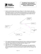
2.2.3.2 Vertical Separation Configuration
The Vertical Separation configuration is recommended in cases where the BTS is relatively far and
the service coverage area is relatively small.
In Vertical Separation configuration, the Donor antenna can be installed either above or below the
Service antenna on a COMMON tower. It is required to set the distance between them to achieve
maximum isolation.
The figures below illustrate the installations.
Figure
2-1. Service above Donor Antenna Figure
2-2. Donor above Service Antenna
2.2.3.3 Horizontal Separation Configuration
In the Horizontal Separation configuration, the Donor and Service antennas are installed on two
separate towers at approximately the same height. The towers can be either on the same side of the
building or on different sides of the building as shown below.
Figure
2-3. Donor and Service Antennas
Installed on Separate Towers
Figure
2-4. Service and Donor Antennas Installed
on Opposite Sides of the Building

D-MBR 3707-3708 PS NFPA CLASS A SIGNAL BOOSTER
PRODUCT DESCRIPTION AND USER’S MANUAL
www.cobham.com/wireless
Date: 17-Jan-16
Cobham Wireless – Coverage
Page | 10 Rev. 1.1 Doc. No.00060CDUM
2.2.3.4 Verifying Isolation between Donor and Service Antennas
Note the following:
• The isolation between the Donor and Service antennas is critical especially for high gain, outdoor
applications.
• For proper operation of the Signal Booster, it is recommended that the isolation between the
Donor and Service antennas be at least 15dB higher than the Signal Boosters set gain. (Lower
isolation can lead to high in-band ripple, oscillations and low signal quality.)
• Ensure proper vertical or horizontal distance separation between Donor and Service antennas
To measure the isolation, proceed as follows:
1. Inject a known signal from a signal generator into one antenna (preferably the Donor antenna).
2. Measure the coupled output from the Service antenna, using the Spectrum analyzer and LNA if
applicable.
3. Perform this procedure across the frequency range of both the Uplink and Downlink bands.
4. Register the lower result for system operation.
2.3 Required BTS Information
Required BTS Information
• BTS channels
• BTS output power per channel
• BTS antenna gain
• BTS antenna height and distance from antenna site
2.4 Selecting the Booster Location
When selecting a location, verify the requirements described in this section are met.
2.4.1 Installation Location Criteria and Environment
WARNING!! The signal booster must always be installed vertically with the connectors on
the underside for protection (see 3.3.3.4). Horizontal installation on a bench for long time may cause
damage to the signal booster due to over-heating.
The following criteria should be considered when selecting the Signal Booster installation site
location:
• Application type – indoor or outdoor
• Distance from antenna site and BTS antenna height.
It is recommended that the installation location be as close as possible to the antenna site in
order to maintain the cable loss to a minimum.
• General surroundings and accessibility of location
• In outdoor applications it is recommended to install a cabinet or a shielding sunroof for further
protection against weather wear.
• Use a suitable mounting surface, such as a flat back rigid wall.

D-MBR 3707-3708 PS NFPA CLASS A SIGNAL BOOSTER
PRODUCT DESCRIPTION AND USER’S MANUAL
Cobham Wireless – Coverage
Date: 17-Jan-16
www.cobham.com/wireless
Doc. No.00060CDUM Rev. 1.1 Page | 11
2.4.2 Verifying the Link between the BTS and the Signal Booster
This test checks the signal strength from the BTS antenna to the Signal Booster.
Proceed as follows:
1. Using a Spectrum analyzer, measure the received signal from BTS at the Donor antenna port
near the Signal Booster.
2. Adjust the Donor antenna direction to receive the maximum signal strength.
3. Compare the received signal strength with the calculated signal strength from the design phase.
In case of discrepancy, check for one of the following:
• Antenna out of direction
• Antenna tuned to side lobe instead of main lobe
• Antenna connector or antenna cable faulty
• Line-of-sight problem (obstruction), etc.
4. Register the signal strength of the downlink channel for the system operation phase.

D-MBR 3707-3708 PS NFPA CLASS A SIGNAL BOOSTER
PRODUCT DESCRIPTION AND USER’S MANUAL
www.cobham.com/wireless
Date: 17-Jan-16
Cobham Wireless – Coverage
Page | 12 Rev. 1.1 Doc. No.00060CDUM
2.5 RF Cable Installation Guidelines
Note the following:
• For all coaxial connections to/from the Signal Booster - high performance, flexible, low loss 50
ohm coaxial communications cable.
• All cables shall be weather-resistant type.
• If the coaxial cables are NOT weather-resistant type: wrap the exterior coaxial cables with
insulation and holding tape (Type 3M Rubber splicing tape) for environmental protection and to
ensure longer lifetime.
• Cable length - determined by the Signal Booster installation plan. When calculating the cable
length, take into account excess cable slack so as not to limit the insertion paths.
/