Page is loading ...

In accordance with our policy of continuous product development and improvement,
this information is subject to change at any time without notice.
EI213425 Revision B (JRM/KAZ) 09/03/98
Manitowoc Beverage Equipment
2100 Future Drive Sellersburg, IN 47172-1868
Tel: 812.246.7000, 800.367.4233 Fax: 812.246.9922
www.manitowocbeverage.com
Foodservice Group
NONO
NONO
NO
TICE!!TICE!!
TICE!!TICE!!
TICE!!
NONO
NONO
NO
TICE!!TICE!!
TICE!!TICE!!
TICE!!
Install Circuit Board onto
Six (6) Plastic Stand-off’s
on the Keyboard Brackets
before installing in the
Dispensing Tower.


In accordance with our policy of continuous product development and improvement,
this information is subject to change at any time without notice.
EI213425 Revision B (JRM/KAZ) 09/03/98
Manitowoc Beverage Equipment
2100 Future Drive Sellersburg, IN 47172-1868
Tel: 812.246.7000, 800.367.4233 Fax: 812.246.9922
www.manitowocbeverage.com
Foodservice Group
Multiplex Beverage Equipment Installation Instructions for
Quad 4-Size Selection Panel and Timer
Assembly Retrofit Kit
for Models 146 and 156 Portion Control Dispensing Towers
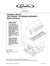
AC Volt Reading Between Pins
A & C A & B B & C
22-30 VAC Ø VAC 22-30 VAC
Grn/Yel
Red
Black
Power supply
connector
from tower.
C Male Pin
A Female Pin
B Female Pin
Introduction
These instructions cover the installation and calibration of
the Multiplex Quad four size selection panel and timer kit.
The Quad selection panel is designed to replace the existing
three size selection panel(s) and all portion control timers in
your Multiplex model 146 or 156 portion control dispensing
tower. The new Quad selection panel kit features four size
portion control per valve, and an easy to program portion con-
trol timer, with special features.
Conducting Test No. 1
Unplug power supply connector from existing portion con-
trol inside tower. Verify proper power supply with AC volt meter.
Caution: This device must be connected properly to a
dual 24 VAC power supply. Perform one of the following
tests before using this new portion control.
Note: If these readings cannot be obtained, do not power
device. Call for service.
If you cannot verify a proper power supply with an AC volt
meter, proceed with the installation instructions listed be-
low, then conduct Test 2 as directed (after step 12).
Figure 1

4
EI213425 Revision B (JRM/KAZ) 09/03/98
Equipment Installation Instructions
Caution
DO Adhere to all National and Local Plumbing and Electrical Safety Codes.
DO Turn “off” incoming electrical service switches when servicing, installing, or
repairing equipment.
DO Check that all flare fittings on the carbonation tank(s) are tight. This check
should be performed with a wrench to ensure a quality seal.
DO Inspect pressure on Regulators before starting up equipment.
DO Protect eyes when working around refrigerants.
DO Use caution when handling metal surface edges of all equipment.
DO Handle CO2 cylinders and gauges with care. Secure cylinders properly against
abrasion.
DO Store CO2 cylinders in well ventilated areas.
DO NOT Store CO2 cylinders in temperature above 125°F (51.7°C) near furnaces,
radiator or sources of heat.
DO NOT Release CO2 gas from old cylinder.
DO NOT Touch Refrigeration lines inside units, some may exceed temperatures of
200°F (93.3°C).
WARNING: DANGER OF ELECTRICAL SHOCK
Disconnect and lock out all electrical power sources
before performing service or maintenance on this
machine -- except when electrical tests are being
performed by qualified service personnel.

5
EI213425 Revision B (JRM/KAZ) 09/03/98
Equipment Installation Instructions
Removing Old Panel
1. Turn dispensing tower power switch to the “off” posi-
tion.
2. Remove the tower lid.
3. Affix the portion control timer calibration label supplied
to the inside of the tower lid.
4. Disconnect all electrical connections from the timers and
from the selection panel. This includes:
One (1) 3 pin connector
Six (6) 2 pin connectors
Six (6) 4 pin rear keyboard connectors (if present)
5. Model 156 Towers Only Loosen the two (2) selection panel
clamping screws on the back upper left and right of the
selection panel.
Model 156 Towers Only Remove the two (2) selection
panel holding screws on the upper left side and right side
of the selection panel.
6. Loosen (do not remove) the six (6)
5
/16" nuts located at
the bottom back side of the selection panel.
Model 14,15 Towers (SEV Valves Only) Remove three (3)
screws across bottom bracket, instead of loosening
5
/16"
nuts.
7. Remove the selection panel center brace (supporting bot-
tom center of selection panel), if included. Slide the se-
lection panel straight up and remove. Remove rear selec-
tion panel if necessary. You may have to pry old panel
from tower due to syrup build up.
Installing New Panel
1. Loosen the six (6)
5
/16" nuts on the bottom of the new
selection panel. Slide the new selection panel and timer
assembly into place in the tower.
Model 156 Towers Only - Do not use stainless/steel right
and left trim pieces from the old keyboard with the new
keyboard.
Model 14,15 Towers (SEV Valves Only) - Remove bottom
bracket from old selection panel, use on new one. Re-
place only two (2) sides screws (center one not acces-
sible), when mounting to tower.
2. Model 146 Towers Only - Tighten the two (2) selection
panel clamping screws on the back upper left and right of
the selection panel.
Model 156 Towers Only - Install the two (2) selection
panel holding screws (removed in step 5), on the upper
left side and right side of the selection panel.
If replacing rear keyboard, slide the new rear selection
panel into place, and install the two (2) upper right and
left side holding screws, and tighten the three (3) screws
across bottom bracket.
3. Lightly tighten the six (6)
5
/16" nuts located at the bottom
of the new front selection panel.
4. Install the selection panel center brace (removed in
step 7).
Note: See the attached MOV instructions.
5. Existing capacitors on water and soda switches must be
replaced with the supplied MOV’s, to protect the new
portion control from voltage spikes.
6. Attach the electrical connection (removed in step 4), to
the new timer assembly and selection panel. All connec-
tions are mated.
One (1) pin connector
Six (6) pin connector.
7. Test all valves stations for activation from new selection
panel(s).
8. Replace the dispensing tower lid.
9. Calibrate all valves.
Conducting Test No. 2
Note: Perform Test 2 if the power supply was not verified
with an AC Volt meter.
1. Push the power “on/off” switch to the “on” position.
2. Immediately try the STOP/FILL switch on Valve No. 1.
3. If Valve No. 1 STOP/FILL pad produces a dispense, con-
tinue with testing the dispensing tower and calibrating.
Power supply should be proper.
Valve Calibration
Setting The Water Flow Rate
Check that the Primary CO
2 tank high pressure regulator or
bulk CO2 regulator is adjusted properly. The Medium pressure
regulator for sugar-based syrup must be adjusted to 60 psi.
The Low pressure regulator for sugar-free syrup must be ad-
justed to 14-16 psi.
1. Turn “off” the syrup at the dispensing valve by turning
the syrup shut-off (located on the valve mounting block).
If there is no syrup shut-off, use a syrup separator.

6
EI213425 Revision B (JRM/KAZ) 09/03/98
Equipment Installation Instructions
2. Check the water shut-off (if applicable). It should be in
the full open position.
Note: The syrup and water shut-offs (if equipped) are not
to be used as an alternate for flow controls. They are to be
used only for shutting on or off the syrup and/or the water
supply.
3. Place a volume cup with 10 oz measurement line, under
valve to be adjusted. If using a syrup separator, place
volume cup under water side of separator only.
4. Use 4-Size portion control timer option to obtain an accu-
rate 4 second pour as follows:
a. Press CAL pad three (3) times in less than 3 seconds
to enter calibrate mode. Calibrate lamp will light
(omit this step if already in calibrate mode).
b. Press STOP-FILL pad of valve to be adjusted once to
cause 4 second pour into volume cup.
Note: Fast-fill valves will dispense 10 oz in 4 seconds and
standard-fill valves will dispense 5 oz in 4 seconds. Diet and
other products with high foaming tendencies should be ad-
justed to 7.6 oz or 3.8 oz respectively.
5. To adjust the water flow rate (if necessary), turn the ad-
justing screw clockwise to increase and counterclockwise
to decrease the flow of water.
6. Repeat 4 second dispense (STOP-FILL pad) and water flow
adjustment, until volume is correct.
7. Open syrup shut-off or remove syrup separator (if appli-
cable).
8. Repeat this procedure (steps 1 through 7 above) for each
valve.
9. Press CAL button once to exit calibrate mode. Calibrate
lamp will go “off”.
Setting Water To Syrup Ratio
1. Remove valve nozzle by turning the nozzle and pulling
down.
2. Place syrup separator on valve to be adjusted. Manually
depress and hold the STOP- FILL pad until both syrup and
water flow out of the syrup/water separator.
3. Position the proper ratio cup under the syrup separator.
Manually depress and hold the STOP-FILL pad. Dispense
until at least
3
/4 of the ratio cup is filled. Both products
should be at the same level.
4. To adjust the syrup flow (if levels are not equal), turn the
syrup flow control adjusting screw clockwise to increase
and counterclockwise to decrease the flow of syrup.
5. After syrup is adjusted, remove the syrup separator and
replace the valve nozzle.
6. Repeat this procedure (steps 1 through 5 above) for the
remaining valves.
Setting Drink Portion Sizes
1. To enter portion control calibrate mode, press CAL pad
three (3) times in less than 3 seconds. Calibrate lamp will
light.
2. Use volume cup with finished drink marking lines, or use
correct size sample cup with desired volume of ice.
3. Press and hold respective SIZE pad until product gets closer
to proper finished drink mark, or until close to top of
sample cup.
4. Release SIZE pad before reaching final mark or before
foam exceeds final mark. Press SIZE pad again momen-
tarily, as many times as is necessary (letting foam settle),
to get to the correct finished drink mark.
5. Repeat steps 2 through 4 above for all sizes and all sta-
tions (producers) needing calibration. Be sure to use the
correct volume cup finished drink marking line, or cor-
rect sample cup size and ice amount, for each size pad.
Note: If you fill above the final mark or need to “start
over” for any reason, you must exit the calibrate mode and
then re-enter the calibrate mode to resume.
6. Exit calibrate mode by pressing CAL pad once. Calibrate
light will go out. All changes will be permanently saved.
/