Page is loading ...

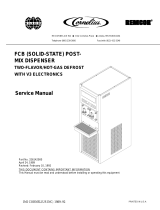
LANCER INSTALLATION GUIDE
The dispenser is for indoor use only. This appliance is to be installed in a location where its use can be overseen by trained
personnel. This unit is not a toy. Children should be supervised not to play with appliance. It should not be used by children or
inrm persons without supervision. This appliance is not intended for use by persons (including children) with reduced physical,
sensory or mental capabilities, or lack of experience and knowledge, unless they have been given supervision or instruction
concerning use of the appliance by a person responsible for their safety. Cleaning and user maintenance shall not be performed by
children without supervision. The min/max ambient operating temperature for the dispenser is 4°C to 32°C (40°F to 90°F). Do not
operate unit below minimum ambient operation conditions. Should freezing occur, cease operation of the unit and contact
authorized service technician. Service, cleaning and sanitizing should be accomplished only by trained personnel. Applicable safety
precautions must be observed. Instruction warnings on the product being used must be followed.
! Intended Use
ABOUT THIS MANUAL
This booklet is an integral and essential part of the product and
should be handed over to the operator after the installation and
preserved for any further consultation that may be necessary.
Please read carefully the guidelines and warnings contained
herein as they are intended to provide the user with essential
information for the continued safe use and maintenance of the
product. In addition, it provides GUIDANCE ONLY to the user on
the correct services and site location of the unit.
BEFORE GETTING STARTED
Each unit is tested under operating conditions and is thoroughly
inspected before shipment. At the time of shipment, the carrier
accepts responsibility for the unit. Upon receiving the unit,
carefully inspect the carton for visible damage. If damage exists,
have the carrier note the damage on the freight bill and le a
claim with carrier. Responsibility for damage to the dispenser lies
with the carrier.
The installation and relocation, if necessary, of this product must be carried out by qualied personnel with
up-to-date safety and hygiene knowledge and practical experience, in accordance with current regulations.
IMPORTANT SAFETY INSTRUCTIONS
FOR QUALIFIED INSTALLER ONLY. This basic Installation Sheet is an initial release. If a complete Operations
Manual (for the unit being installed) is required or needed, please refer to the Lancer web site (lancercorp.com) for
immediate access, or for your convenience, scan this QR code with a mobile device (app required) for immediate
access to other Technical Documents and alternative translations (if available) pertaining to this unit. Contact Lancer
Customer Service for assistance as required.
®
320
Lancer PN: 28-0955/02
Revision: 02-1, August 2018

2
• WARNING: Carbon Dioxide (CO
2
) is a colorless, noncombustible gas with a light pungent odor. High percentages of CO
2
may
displace oxygen in the blood.
• WARNING: Prolonged exposure to CO
2
can be harmful. Personnel exposed to high concentrations of CO
2
gas will experience
tremors which are followed by a loss of consciousness and suocation.
• WARNING: If a CO
2
gas leak is suspected, immediately ventilate the contaminated area before attempting to repair the leak.
• WARNING: Strict attention must be observed in the prevention of CO
2
gas leaks in the entire CO
2
and soft drink system.
5 Carbon Dioxide (CO
2
)
Appliance is not suitable for installation where a water jet could be used. Provide an adequate potable water supply. Water pipe
connections and xtures directly connected to a potable water supply must be sized, installed, and maintained according to
federal, state, and local laws. The water supply line must be at least a 3/8 inches (9.525 mm) pipe with a minimum of 20 PSI (0.137
MPa) line pressure, but not exceeding a maximum of 65 psi (0.448 MPa). Water pressure exceeding 65 psi (0.448 MPa) must
be reduced to 65 psi (0.448 MPa) with the provided pressure regulator. Use a lter in the water line to avoid equipment damage
and beverage o-taste. Check the water lter periodically, as required by local conditions. The water supply must be protected by
means of an air gap, a back ow prevention device or another approved method to comply with NSF standards. A leaking inlet
water check valve will allow carbonated water to ow back through the pump when it is shut o and contaminate the water supply.
Ensure the back ow prevention device complies with ASSE and local standards. It is the responsibility of the installer to ensure
compliance.
! Water Notice
SPECIFICATIONS
DIMENSIONS
Width: 9.2 inches (235 mm)
Depth: 17.1 inches (433 mm)
Height: 26.9 inches (682 mm)
WEIGHT
Shipping: 40 lbs (18.14 kg)
Operating: 35 lbs (15.88 kg)
CARBON DIOXIDE (CO
2
) SUPPLY
Min Pressure: 70 psi (0.483 MPa)
Max Pressure: 80 psi (0.552 MPa)
FITTINGS
Carb Water Inlet: 3/8 inch (9.5 mm) barb
Carb Water Outlet: 3/8 inch (9.5 mm) barb
Plain Water Inlet: 3/8 inch (9.5 mm) barb
Brand Syrup Inlets: 3/8 inch (9.5 mm) barb
Drain Fitting: 5/8 inch (15.9 mm) barb
ELECTRICAL
24 VDC / 2.0 Amps
FLOW RATE
1.5 - 2.0 ounces per second
PLAIN WATER SUPPLY
Min Flowing Pressure: 20 psi (0.137 MPa)
Max Static Pressure: 65 psi (0.448 MPa)
This unit emits a sound pressure level below 70 dB
Appliance must be supplied by 24 VDC. Check dispenser name plate label, located inside tower panels, for the correct electrical
requirements of unit. Do not plug into a wall electrical outlet unless the current shown on the name plate label agrees with local cur-
rent available. Follow all local electrical codes when making connections. Each dispenser must have a separate electrical circuit.
Do not use extension cords with this unit. Do not ‘gang’ together with other electrical devices on the same outlet. The keyswitch
does not disable the line voltage to the transformer primary. Always disconnect electrical power to the unit to prevent personal
injury before attempting any internal maintenance. The resettable breaker switch should not be used as a substitute for unplugging
the dispenser from the power source to service the unit. Only qualied personnel should service internal components of electrical
control housing. Make sure that all water lines are tight and units are dry before making any electrical connections!
F Electrical Warning
Your Service Agent:
Service Agent Telephone Number:
Serial Number:
Model Number:
This manual was developed by the Lancer Corporation as a reference for the owner/operator and installer of this
dispenser. Please read this guide before installation and operation of this dispenser. If service is required please call your
Lancer Service Agent or Lancer Customer Service. Always have your model and serial number available when you call.
READ THIS MANUAL

3
INSTALLATION
Unpack the Dispenser
1. Cut package banding straps and remove.
2. Open the box and remove the accessory kit and loose parts.
3. Carefully lift the unit out of the box and place on a at
surface taking care to not scratch the plastic covers.
Inspect unit for concealed damage. If evident, notify
deliveringcarrierandleaclaimagainstthesame.
NOTE
Selecting/Preparing Counter Location
Dispenser Installation
1. Using proper lifting techniques, lift the tower over the counter
top, then route end of power cord through the designated
opening in the counter.
2. Slide the tower into the cutout in the counter and use the
screws and mounting brackets provided to secure the tower
to the counter.
Inspect the counter location where the unit is to be
installed. Verify the selected counter is strong enough
to safely support the weight of the installed unit, after
the cutout for the unit is made. The ideal counter for
installation should measure at least 25 mm (1 inch)
thick.
! ATTENTION
1. Select a location that is in close proximity to a properly
grounded electrical outlet, within ve (5) feet (1.5 m) of
a drain, and a water supply that meets the requirements
shown in the Specications section found on page 2.
To assure that beverage service is accessible to all
customers, Lancer recommends that counter height
and equipment selection be planned carefully. The
2010 ADA Standards for Accessible Design states that
themaximumreachheightfromtheoorshouldbeno
more than 48 in (1.2 m) if touch point is less than 10 in
(254 mm) from the front of the counter, or a maximum
of 46 in (1.17 m) if the touch point is more than 10 in
(254 mm) and less than 27 in (685 mm) from the front of
the counter. For more information about the customer’s
legal requirements for the accessibility of installed
equipment, refer to 2010 ADA Standards for Accessible
Design - http://www.ada.gov.
NOTE
When attaching the tower to the counter, make sure the
screws do not extend more than 0.75 in (19 mm) from
the top of the counter. These could damage the valves
when installing the dispenser.
! ATTENTION
Min: 0.75 in
Max: 2.75 in
Min: 2.0 in
Max: 1.5 in
Max: 48.0 in
A. Drain Tube
B. Inlet Tubes
A
B
3. Select a location for the remote chiller system or carbonator
(if necessary), syrup pumps, CO
2
tank, syrup containers,
and water lter (recommended).
4. Using Counter Cutout Template provided (and on the back
of this manual) cut out required opening for the tower
installation in the designated location.
NSF listed units must be sealed to the counter.
NOTE
A
B
C
A. Tower
B. Syrup/Water Inlets
C. Mounting Brackets
(Underneath Counter)
D. Connection Screws
(Underneath Counter)
D
C
3. Route appropriate tubing from the syrup pump location to the
syrup inlets on the tower. Connect tubing to inlets using the
oetiker pliers and ttings. Repeat for all syrup connections.
The dispenser should only be installed in a location
where it can be overseen by trained personnel
NOTE
2. Select a location that utilizes the clearances/space required
for installation.

4
7. Plug in power cord to power supply then route power supply
cord to the designated grounded electrical outlet.
DO NOT PLUG UNIT INTO GROUNDED ELECTRICAL
OUTLET AT THIS TIME. Make sure that all water lines
are tight and unit is dry before making any electrical
connections
! WARNING
4. Route appropriate tubing for the carbonated/plain water
inlets then connect tubing to inlet. Repeat for all water
connections including the return inlet.
A
B
A. Tower
B. Drip Tray
C. Magnet Connection
in Tower
C
A
D
E
C
B
A. Drip Tray
B. Counter
C. Upper Drain Fitting
D. Lower Drain Fitting
E. Washer
6. If a drain line is to be utilized, place gasket at the bottom of
the drain then attach drain tting to drip tray.
If a drain line is utilized, then connect ADA wire
harness in drip tray to the wire harness behind splash
plate before attaching drip tray.
! ATTENTION
Dispenser Setup
1. Remove the cup rest from drip tray.
2. Remove the nozzle by twisting clockwise and pulling down.
8. Connect power cord to grounded electrical outlet.
Unit is designed to be supported by a remote chiller
system or remote ice cooled system. Please see the
manufacturer’sspecicationsandinstructionsfor
installation. The following are the instructions for
plumbing the remote chiller system to the tower.
NOTE
A. Nozzle
A
3. Remove the splash plate.
4. Turn on the water supply.
5. Verify all Bag-in-Box contain syrup and check for leaks.
6. Open the pressure relief valve located on the remote chiller
system by ipping up on the valve cap lever. Hold open until
water ows from the relief valve then close (ip down) relief
valve. (If applicable)
7. Using a screwdriver, remove the top two screws of the top
plate then slide plate back slightly and lift from the front edge
to remove.
A. Top Plate Screw
B. Touchscreen
A
A
B
8. Route appropriate tubing from the syrup pump location to
the syrup inlets at the remote chiller. Repeat for all syrup
connections.
9. Route appropriate tubing from the water source to the water
inlet at the remote chiller and only connect tubing to the
water source.
10. Turn on the water and ush the water line thoroughly.
11. Turn o the water and connect water line to the plain water
inlet at the remote chiller.
A
B
C
A. Oetiker Pliers
B. Fitting
C. Tubing
D. Syrup/Water
Inlet
D
5. Slide drip tray into opening in tower until magnets engage
and lock drip tray in place. Connect ADA wire harness from
drip tray to ADA wire harness in tower.

5
The dispenser must be properly electrically grounded
to avoid serious injury or fatal electrical shock. The
power cord has a three-prong grounded plug. If a
three-hole grounded electrical outlet is not available,
use an approved method to ground the unit. Follow all
local electrical codes when making connections. Each
dispenser must have a separate electrical circuit. Do
not use extension cords. Do not connect multiple
electrical devices on the same outlet.
F WARNING
9. Turn on the power to the dispenser by ipping the power
switch, located underneath the top plate removed in Step 7.
10. Once the screen has booted up, access the service menu by
placing your nger at the top, right corner of the screen.
11. In one swift, uid motion slide your nger along the top of the
screen to the left till you reach the upper left corner of the
screen, then hold your nger to the screen for a minimum of
two (2) seconds.
- Slide Finger to Left and Hold
13. A keypad will appear, enter the designated pin number to
access the service menu.
Contact Lancer Technical Support for the units’
designated pin number.
NOTE
- Enter Designated PIN #
14. For manager’s access to the service menu, press and hold
the upper, right-hand corner of the screen for a minimum of
ve (5) seconds and enter the manager’s pin number (6655).
The manager’s access to the service menu allows
access to the Lighting screen (page 12), the Sold Out
screen (page 11), and the Time & Delays screen (page
13).
NOTE
15. To lock the dispenser, or put it in “sleep” mode, repeat Step
13 but instead enter the lock code (3.14).
12. After you have held your nger to the upper left corner for
a minimum of two (2) seconds, tap all four corners of the
screen in any order.
This mode prevents users from dispensing drinks and
acts as a power saving tool while the unit is not in use.
NOTE
16. For access to only the Sold Out Menu, repeat Step 13 and
enter the Sold Out pin (963.).

6
Once the purge is activated, it will continue to dispense
product until it is deactivated. To deactivate the purge,
simply press the Purge button again. Up to four
modules can be purged at one time. Once four
modules are selected, all other modules are grayed out
and cannot be selected.
NOTE
A. Regulator Adjustment Screw
B. Adjust to 65 PSI (0.448 MPa)
C. Wrench
A
B
C
Adding New Brand/Flavor Module
1. In order to add a new brand or avor module, the module
must rst be activated.
2. From the Service menu, press the Valve Conguration
button.
3. Press the Valve Type tab on the far left side of the screen,
then select any of the inactive modules.
23. Purge the carbonated water module until gas-out.
24. Reactivate the pump deck at the remote chiller.
25. Purge the carbonated water module again until a steady ow
of carbonated water is achieved.
26. Purge each syrup module until a steady ow of syrup is
achieved.
A. Purge Tab
B. Up to 4 Purge Buttons Selected
C. ‘Grayed Out’ Purge Button
A
B
C
18. Press the Purge tab on the far left side of the screen.
19. Press the Purge buttons for both the plain water and the
carbonated water modules.
A. Valve Type Tab
B. Valve Type Button
A
B
20. Once a steady ow of water is achieved, press the Purge
button again to deactivate the modules.
21. Ensure that the pump deck at the remote chiller is turned o
before turning on the CO
2
.
22. Turn on CO
2
at the source then, using a screwdriver, adjust
the high pressure regulator at the source to 65 PSI (0.448
MPa) then tighten locknut with wrench.
A
B
D
C
A. Discard Changes C. Maintenance Button
B. Valve Conguration D. Locale Change
17. From the service menu press the Maintenance button.

7
A. Valve Function
B. Valve Type
A
B
4. From here, choose the desired function and valve type for
the incorporated valve module.
5. Press the Valve Conguration button to return to the Valve
Conguration menu.
6. Repeat steps 3 and 4 for any other desired brand or avor
modules.
7. From the Valve Conguration menu, press the Congure tab
on the far left side of the screen.
8. Press the Congure button under any of the activated brand
or avor modules to open its Conguration Page.
9. Select a new brand from the available Brands Library tabs
on the left side of the screen.
Each brand has a default water type and ratio when
they are selected. The water type and ratio can be
adjusted if necessary, however, adjusting the ratio here
is purely representational and does not set the ratio
forthenisheddrink.Adjusttheratiobyselectingthe
Ice or No Ice ratio using the buttons in the upper right
corner of the screen, or by manually adjusting the ratio
by tapping the number and entering the new value on
the keypad.
NOTE
10. Once a brand/avor has been selected to a corresponding
module, press the Valve Conguration button to return to the
Valve Conguration Screen.
11. Repeat Steps 8 and 9 for any other desired brand or avor
modules.
12. Press the Menu button to return to the Service menu.
13. From the Service Menu, press the Maintenance button.
14. Press the Purge tab on the far left side of the screen.
15. Purge any new brand or avor module until there is a steady
ow of syrup. (See page 6)
16. Press the Menu button to return to the Service Menu.
A. Congure Tab D. Brand Water Type
B. Congure Button E. Brand Ratio
C. Activated Module
A
B
C
D
E
A
B
D
C
A. Brand Library Tab C. Brand Ratio
B. Replacement Brand D. Water Type

8
CALIBRATION & MAINTENANCE
Calibrating Plain Water Module
1. Re-install nozzle. (See page 4)
2. From the Service menu, press the Maintenance button.
3. Press the Calibrate tab on the far left side of the screen and
press the Calibrate button for the plain water module.
4. Enter the desired ow rate in milliliters per second (ml/sec).
This number is based on the target nished drink ow rate of
60 ml/sec and the desired drink ratio.
Finisheddrinkowrate=60ml/sec
Ratio=7:1
60ml/sX7/(7+1)=52.5ml/secwaterowrate
60ml/sX1/(7+1)=7.5ml/secsyrupowrate
EXAMPLE
5. Set the Timer to the ON position and select milliliters (ml) as
the desired unit of measurement.
6. Using the keypad, enter a specic volume to be dispensed
based on the size of the graduated cylinder being used to
calibrate the plain water module. The larger the volume
dispensed, the more accurate the results. Use the example
150 ml.
7. With the graduated cylinder placed in a position below the
nozzle, press the Start Purge button. The unit will dispense
the volume designated in the previous step.
A. Graduated Cylinder
B. Nozzle
A
B
8. Examine the dispensed volume in the graduated cylinder.
9. If the dispensed volume does not match the value (150 ml)
entered on the screen in step 5, remove the protective cap
for the corresponding valve and use a screwdriver to adjust
the water ow control. (See Plumbing Diagram on page 16
for reference).
A
B
C
D
Increase Decrease
A. Flow Control
B. Valve Retainer
C. Solenoid
D. Valve Body
10. Repeat steps 7-9 until the designated volume of 150 ml in
step 5 is achieved.
11. Repeat steps 3-10 for the carbonated water module, if valve
is present.
A. Enter Flow Rate C. Start Purge Button
B. Timer Icon D. Unit Icon
A
B
C
D

9
A. Graduated Cylinder
B. Nozzle
A
B
Calibrating Brand Syrup Modules
A
B
C
D
Increase Decrease
A. Flow Control
B. Valve Retainer
C. Solenoid
D. Valve Body
4. Set the Timer to the ON position and select seconds (s) as
the desired unit of measurement.
5. Using the keypad, enter in a time of 4 seconds as the preset
dispensing time.
9. Repeat steps 6-8 until the designated volume of 30 ml is
achieved.
10. Repeat steps 2-9 for the remaining brand syrup modules.
11. Press the Maintenance button to return to the Maintenance
screen and then press the Menu button to return to the
Service menu.
1. From the Service menu, press the Maintenance button.
2. Press the Calibrate tab on the far left side of the screen and
press the Calibrate button for the rst brand syrup module.
3. The water ow rate should be set from the calibration of
the plain water module in the previous section and the ratio
should be determined from when the brand was congured.
(See page 6, Adding New Brand/Flavor Module)
The refrigeration unit should have been running for at
leastone(1)hourbeforeattemptingtosetowrates
on valves. The drink temperature should be no higher
than40°F(4.4°C)whenowratesareset.Thisisbest
done after the remote chiller has already made an ice
bank. (If applicable)
NOTE
The brand syrup modules can be calibrated the same
as the plain water module by using volume (ml). Below
are the steps to calibrate the modules using the unit of
time (seconds) instead of volume (ml).
NOTE
7. Examine the dispensed volume in the graduated cylinder.
8. If the dispensed volume does not match the value of 30.0
ml, (see table on next page) remove the protective cap for
the corresponding valve and use a screwdriver to adjust the
brand syrup ow control.
Thenisheddrinkowratewassetto60ml/sec,
whichmakesthenishedsyrupowrate7.5ml/s.In4
seconds, the volume of syrup that should be
dispensed is 30 ml.
NOTE
6. With the graduated cylinder placed in a position below the
nozzle, press the Start Purge button. The unit will dispense
the designated syrup for 4 seconds.
A. Flow Rate/Ratio C. Start Purge Button
B. Timer Icon D. Unit Icon
A
B
C
D

10
Ratio Settings Table:
The table below shows the ow rate for the plain water modules and the volume of syrup dispensed after a 4 second pour, for dierent
ratio settings (All at a nished drink ow rate of 60 ml/sec):
Ratio 5 5.2 5.4 5.6 5.8 6 6.2 6.4 6.6 6.8 7
Plain Water
Flow Rate (ml/s)
50 50.32 50.63 50.91 51.18 51.43 51.67 51.89 52.11 52.31 52.50
Volume of Syrup
(4 sec.) (ml)
40 38.71 37.50 36.36 35.29 34.29 33.33 32.43 31.58 30.77 30
Ratio 7.2 7.4 7.5 7.6 7.8 8 8.2 8.4 8.6 8.8 9
Plain Water
Flow Rate
52.68 52.86 52.94 53.02 53.18 53.33 53.48 53.62 53.75 53.88 54
Volume of Syrup
(4 sec.)
29.27 28.57 28.24 27.91 27.27 26.67 26.09 25.53 25 24.49 24
Calibrating Flavor Modules
1. From the Maintenance menu, press the Calibrate tab on the
far left side of the screen and press the Calibrate button for
any designated avor module.
2. The water ow rate should be set from the calibration of
the plain water module in the previous section and the ratio
should be determined from when the avor was congured.
(See page 6, Adding New Brand/Flavor Module)
3. Set the Timer to the ON position and select seconds (s) as
the desired unit of measurement.
4. Using the keypad, enter in a time of 5 seconds as the preset
dispensing time.
5. With the graduated cylinder placed in a position below the
nozzle, press the Start Purge button. The unit will dispense
the designated avor for 5 seconds.
6. Examine the dispensed volume in the graduated cylinder.
7. If the dispensed volume does not match the value of 10.5 ml,
(see note above) remove the protective cap for the corre-
sponding valve and use a screwdriver to adjust the avor
ow control.
A
B
C
D
A. Flow Rate/Ratio C. Start Purge Button
B. Timer Icon D. Unit Icon
Thenisheddrinkowratewassetto60ml/sec,which
makesthenishedavorowrate2.1ml/s.In
5 seconds, the volume of syrup that should be
dispensed is 10.5 ml.
NOTE
8. Repeat steps 5-7 if any more bonus avor ow adjustment is
necessary.
9. Repeat steps 2-8 for any remaining bonus avor module.
10. Re-install top plate, splash plate, and cup rest. (See page 4)
A
B
C
D
Increase Decrease
A. Flow Control
B. Valve Retainer
C. Solenoid
D. Valve Body

11
Scheduled Maintenance
FEATURES OF THE TOUCHSCREEN TOWER
As Needed
• Keep exterior surfaces of dispenser (include drip tray and cup rest) clean using a clean, damp cloth.
Daily
• Remove outer nozzle and rinse well in warm water. DO NOT use soap or detergent. This will cause
foaming and o taste in nished product.
• Using a soft cloth and cleaning solution, clean the nozzle injectors. See Cleaning and Sanitizing Nozzle
section on page 13 for reference.
• Remove cup rest and wash in cleaning solution.
• Pour warm cleaning solution into the drip tray and wipe with a clean cloth.
• With a clean cloth and cleaning solution, wipe o all of the unit’s exterior surfaces and splash areas.
DO NOT USE ABRASIVE SOAPS OR STRONG DETERGENTS. DO NOT USE AMMONIA BASED
PRODUCTS WHEN CLEANING THE SCREEN OR SURROUNDING PLASTICS.
• Replace the cup rest and nozzle.
Weekly
• Taste each product for o tastes. If o taste occurs clean and sanitize the unit using the appropriate
procedures outlined in the Cleaning and Sanitizing section of this manual.
Monthly
• Clean and sanitize the unit using the appropriate procedures outlined in the Cleaning and Sanitizing
section of this manual.
Every Six Months
• Clean remote chiller according to manufacturer’s instructions (if necessary).
• Clean the entire exterior of the unit.
The following are the features only available from the manager’s access to the service menu (PIN: 6655, see page 5). For
information on more available features, see the TsT User Guide (Lancer PN: 28-0975) and Operation Manual (Lancer PN:
28-0945/02) located on the Lancer website (lancercorp.com) or by the QR code at the beginning of this Installation Guide.
NOTE
Sold-Out Feature
1. From the Service Menu, press the Sold Out button.
2. Manually adjust specic brands to read Ready, Out, or Auto.
Ready-signiesthereisavailableproductandthe
valve will dispense when activated
Out-signiesthereisnoavailableproductorthereisa
problemwiththespeciedbrandandwillnotdispense
when activated.
Auto-signiesthattheconguredSoldOutSensor
controls whether the brand can be dispensed. This
feature requires an optional sold out sensor kit, which
does not come standard, and is available for up to
ten (10) brands at one time. If no sold out sensor is
assigned then the Auto feature acts the same as the
Ready feature.
NOTE

12
A. Screen Brightness
B. Nozzle Brightness (Idle)
C. Nozzle Brightness (Dispensing)
D. Ribbon Light Features
A
D
B
C
A. Screen Brightness
B. Nozzle Brightness (Idle)
C. Nozzle Brightness (Dispensing)
D. Ribbon Light Features
A
D
B
C
A. Old Color
B. New Color
C. Brightness Slider
D. RGB Color Table
A
B
D
C
Lighting Features
1. From the Service menu, press the Lighting button.
2. From this menu, the user can adjust the Screen Brightness
as well as the brightness of the Nozzle Light when the unit is
dispensing and when the unit is not dispensing (Idle).
3. Below the Nozzle Light sliders, the user can change how the
ribbon lights on the side of the dispenser are displayed.
Spectrum - Ribbon lights cycle through preset colors.
The brightness and the speed at which the colors cycle
can be adjusted using the sliders.
One Color - Ribbon lights are displayed using only one
color determined by the user. Press the Color bar to
change the color using the RGB Color Table.
Two Colors - Ribbon lights cycle through two colors
determined by the user. Press the Color bars to change
the colors using the RGB Color Table. The speed at
which the colors cycle can be adjusted using the slider.
NOTE

13
Time & Delays Settings
1. From the Service Menu, press the Time & Delays button to
access the Time & Delays Menu.
2. Update the current Date & Time, if necessary, by tapping the
eld and using the keypad to enter the correct date or time.
Press Set to save the changes.
3. Enable or Disable any of the four (4) Delay functions by
tapping underneath their designated function names: Brand
Timeout, Screen Saver, Sleep, and Dispense Timeout.
4. Adjust the Frequency and Units of Time by selecting their
corresponding elds.
Brand Timeout - the amount of time for a selected
brand on the Pour Screen to be unselected after
inactivity
Screen Saver - the amount of time for the screen saver
to be initiated after inactivity
Sleep - the amount of time for the unit to enter Sleep
Mode (see page 5) after inactivity.
Dispense Timeout - the amount of time a valve will pour
beforeautomaticshuto.
NOTE
CLEANING AND SANITIZING
Cleaning Solution
Mix a mild, non-abrasive detergent (e.g. Sodium Laureth
Sulfate, dish soap) with clean, potable water at a temperature
of 90°F to 110°F (32°C to 43°C). The mixture ratio is one ounce
of cleaner to two gallons of water. Prepare a minimum of ve
gallons of cleaning solution. Do not use abrasive cleaners or
solvents because they can cause permanent damage to the unit.
Ensure rinsing is thorough, using clean, potable water at a
temperature of 90°F to 110°F. Extended lengths of product lines
may require additional cleaning solution.
Lancer equipment (new or reconditioned) is shipped from the factory cleaned and sanitized in accordance with NSF
guidelines. The operator of the equipment must provide continuous maintenance as required by this manual and/or
state and local health department guidelines to ensure proper operation and sanitation requirements are maintained.
ThecleaningproceduresprovidedhereinpertaintotheLancerequipmentidentiedbythismanual.Ifotherequipment
is being cleaned, follow the guidelines established by the manufacturer for that equipment.
Cleaning should be accomplished only by trained personnel. Sanitary gloves are to be used during cleaning operations.
Applicable safety precautions must be observed. Instruction warnings on the product being used must be followed.
GENERAL INFORMATION
• Use sanitary gloves when cleaning the unit and observe all applicable safety precautions.
• DO NOT use a water jet to clean or sanitize the unit.
• DO NOT disconnect water lines when cleaning and sanitizing syrup lines, to avoid contamination.
• DO NOT use strong bleaches or detergents; These can discolor and corrode various materials.
• DO NOT use metal scrapers, sharp objects, steel wool, scouring pads, abrasives, or solvents on the dispenser.
• DO NOT use hot water above 140° F (60° C). This can damage the dispenser.
• DO NOT spill sanitizing solution on any circuit boards. Insure all sanitizing solution is removed from the system.
! ATTENTION
Sanitizing Solution
Prepare the sanitizing solution in accordance with the
manufacturer’s written recommendations and safety guidelines.
The type and concentration of sanitizing agent recommended in
the instructions by the manufacturer shall comply with 40 CFR
§180.940. The solution must provide 100 parts per million (PPM)
chlorine (e.g. Sodium Hypochlorite or bleach) and a minimum of
ve gallons of sanitizing solution should be prepared.
A. Current Date/Time
B. Enable/Disable
C. Frequency
D. Units of Time
A
B
C
D

14
Following sanitation, rinse with end-use product
until there is no aftertaste. Do not use a fresh water
rinse. This is a NSF requirement. Residual sanitizing
solution left in the system creates a health hazard.
! CAUTION
Wiring Diagram
Cleaning and Sanitizing Product Lines
1. Disconnect product lines from BIB’s or other product supply.
2. Place product lines, with BIB connectors, in a bucket of
warm water.
3. Activate each valve to ll the lines with warm water and ush
out product remaining in the lines.
4. Prepare Cleaning Solution described above.
5. Place product lines, with BIB connectors, into cleaning
solution.
6. Activate each valve until lines are lled with cleaning
solution then let stand for ten (10) minutes.
7. Flush out cleaning solution from the syrup lines using clean,
warm water.
8. Prepare Sanitizing Solution described above.
9. Place product lines into sanitizing solution and activate each
valve to ll lines with sanitizer. Let sit for ten (10) minutes.
10. Reconnect product lines to BIB’s and draw drinks to ush
solution from the dispenser.
11. Taste the drink to verify that there is no o-taste. If o-taste
is found, ush product system again.
Following sanitation, rinse with end-use product
until there is no aftertaste. Do not use a fresh water
rinse. This is a NSF requirement. Residual sanitizing
solution left in the system creates a health hazard.
! CAUTION
Cleaning and Sanitizing Nozzle
1. Disconnect power, so as to not activate valve while cleaning.
2. Remove outer nozzle by twisting counter clockwise and
pulling down.
3. Rinse nozzle with warm water.
4. Wash nozzle with cleaning solution then immerse in
sanitizing solution and let sit for fteen (15) minutes.
5. Set nozzle aside and let air dry. DO NOT rinse with water
after sanitizing.
6. Using a soft, clean cloth and cleaning solution, clean the
nozzle injectors.
7. Using a soft, clean cloth sanitize the nozzle injectors and let
air dry.
8. Reconnect nozzle.
9. Connect power.
10. Taste the drink to verify that there is no o-taste. If o-taste
is found, sanitize the nozzle and nozzle injectors again.

15
Counter Cut-out (To Scale)
1.62
[41.28]
5.02
[127.49]
4.13
[101.71]
6.19
[157.30]
CUT ALONG
DOTTED LINES
FRONT OF UNIT

Lancer Corp.
800-729-1500
Technical Support/Warranty: 800-729-1550
lancercorp.com
Plumbing Diagram
S1
S7
S3
S8
S4
SD
PW
S9
S5
RC
S2
S10
S6
S1 SD PW
S3 S4 S5 S6
S7 S8 S9 S10
S2
Item Description
S1 Syrup Line 1
S2 Syrup Line 2
S3 Syrup Line 3
S4 Syrup Line 4
S5 Syrup Line 5
S6 Syrup Line 6
S7 Syrup Line 7
S8 Syrup Line 8
S9 Syrup Line 9
S10 Syrup Line 10
PW Plain Water Line
SD Soda Line
RC Recirculation Line
/