4
DTP T FB 332 and DTP T FB 232 • Setup Guide (Continued)
Extron Headquarters
+800.633.9876 Inside USA/Canada Only
Extron USA - West Extron USA - East
+1.714.491.1500 +1.919.850.1000
+1.714.491.1517 FAX +1.919.850.1001 FAX
Extron Europe
+800.3987.6673
Inside Europe Only
+31.33.453.4040
+31.33.453.4050 FAX
Extron Asia
+65.6383.4400
+65.6383.4664 FAX
Extron Japan
+81.3.3511.7655
+81.3.3511.7656 FAX
Extron China
+86.21.3760.1568
+86.21.3760.1566 FAX
Extron Middle East
+971.4.299.1800
+971.4.299.1880 FAX
Extron Australia
+61.8.8113.6800
+61.8.8351.2511 FAX
Extron India
1800.3070.3777
(Inside India Only)
+91.80.3055.3777
+91.80.3055.3737 FAX
© 2017 Extron Electronics All rights reserved. All trademarks mentioned are the property of their respective owners. www.extron.com
Step 6 — Make top panel connections
G
Audio input (see figure 1 on page 1) — Connect an unbalanced stereo audio source to this 3.5 mm mini stereo jack for an analog
audio input.
H
RS-232 and IR connector — To pass serial or infrared data or control signals on the Over DTP RJ-45 output, connect the controlling
device to the transmitter via the RS-232 and IR captive screw connector. Connect the device to be controlled to the receiver.
I
Configuration port — Plug a PC or other controlling device into the switching transmitter via
this top panel mini-USB connector for remote conguration of the switching transmitter.
J
Reset button — This button initiates two levels of reset. See the DTP T FB 332 and
DTP T FB 232 User Guide, available at www.extron.com, for details.
Operation
After all connected devices are connected and powered on, the system is fully operational.
The DTP T FB unit can be congured and controlled using Extron Simple Instruction Set (SIS)
commands (see the DTP T FB 332 and DTP T FB 232 User Guide available at www.extron.com).
Indicators (
K
, see figure 1)
Power LED — Lights when power is applied.
HDMI LED — Lights when the HDMI input signal is detected.
VGA LED — Lights when the VGA input signal is detected.
HDCP LED — Lights when the HDMI input signal is encrypted.
Auto LED — Lights when device is in auto switch mode. Auto switch is on by default.
When auto switch is on, the switcher automatically selects the input, HDMI or VGA, that has a valid signal present. When signals are
present on both inputs. the switcher selects VGA.
NOTE: Auto switch mode can be toggled off and on using the SIS commands. Issue the EnAUSW} SIS command,
where n = 0 (off) or 1 (on). The switcher responds with Auswn]. See the DTP T FB 332 and DTP T FB 232 User Guide,
available at www.extron.com, for details.
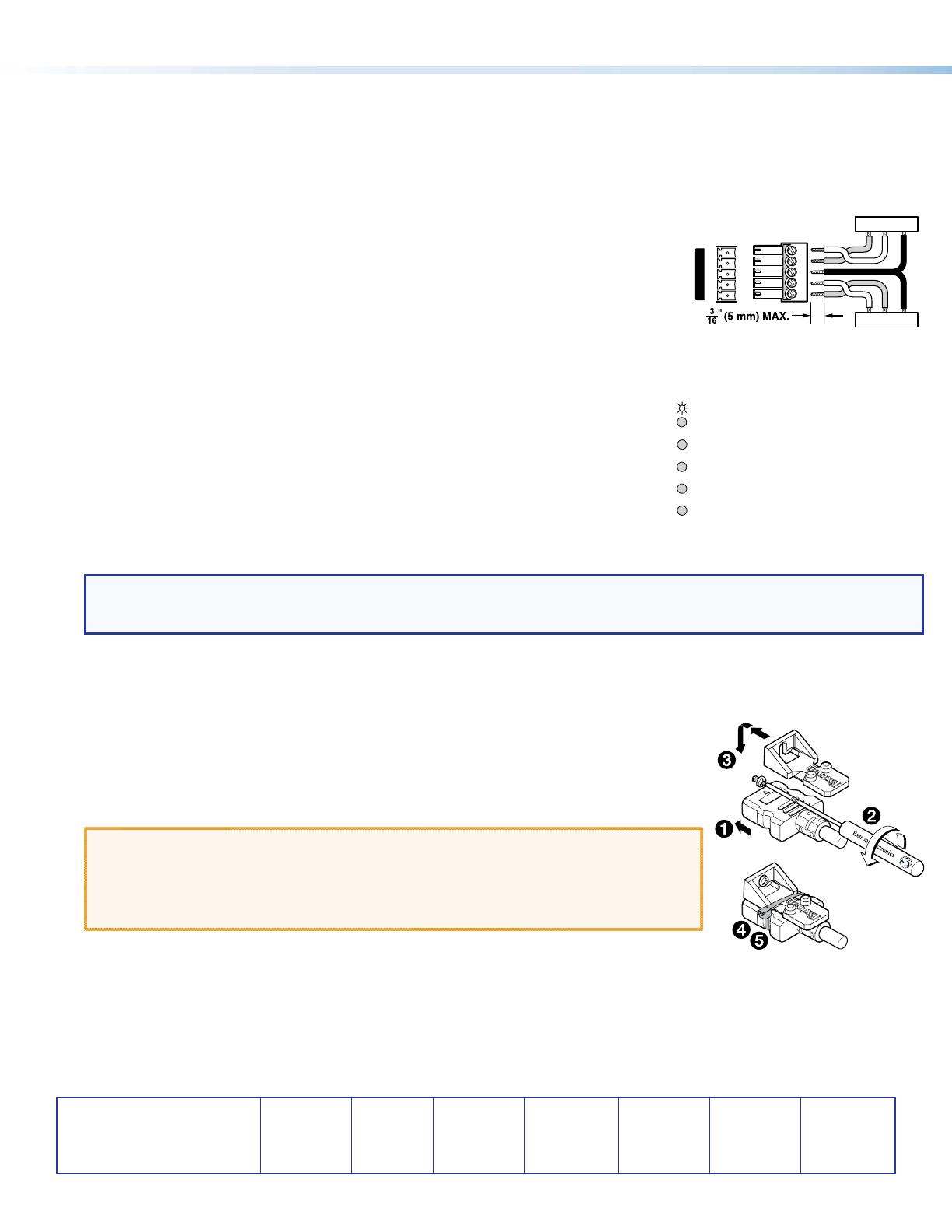
LockIt
®
Lacing Brackets
Use the included LockIt Lacing Brackets to securely fasten the HDMI cable as follows.
1. Plug the HDMI cable into the panel connection.
2. Loosen the HDMI connection mounting screw from the panel enough to allow the LockIt lacing
bracket to be placed over it. The screw does not have to be removed.
3. Place the LockIt lacing bracket on the screw and against the HDMI connector, then tighten the
screw to secure the bracket.
ATTENTION:
• Do not overtighten the HDMI connector mounting screw. The shield it fastens to is very
thin and can easily be stripped.
• Ne serrez pas trop la vis de montage du connecteur HDMI. Le blindage auquel elle est
attachée est très n et peut facilement être dénudé.
4. Loosely place the included tie wrap around the HDMI connector and the LockIt lacing bracket as
shown.
5. While holding the connector securely against the lacing bracket, use pliers or similar tools to tighten the tie wrap, then remove any
excess length.
TxRx
RxTx
Gnd
Gnd
G
RS-232 IR
Rx
Tx
Tx
Rx
3


