Page is loading ...

Public Address System
Intelligent Public Address Center M-2120
M-2140
Operation Instructions
Thank you for using our public address system. To ensure optimal operation of this equipment, please read this
Operation Instructions carefully before use.
LY I n t e r n a t i o n a l E l e c t r o n i c s C o . , L t d .
http://www.lyintlcorp.com/

Information on Operation Instructions
This Operation Instructions involves M-2120 and M-2140 micro intelligent systems for public
address system, including introduction to functions and appearance of products, connection
illustrations, settings, operation instructions, precautions, after-sale services, product performance
and specifications. Please read this Operation Instructions carefully before connection and
operation.
All contents in this Operation Instructions are based on operation of M-2140, which are only for
illustration. Furthermore, operation methods for M-2120 are similar to that of M-2140.
Please keep this Operation Instructions properly for further use.

* Firefighting/Public Address System Micro Intelligent Mainframe
1
Micro intelligent public address system integrates such functions as play, intelligent timing control, audio
matrix, partition control, intelligent firefighting linkage, remote computer control as well as telephone and
remote paging.
Owing to its integral public address functions and individualized intelligent control functions, this address
system can better satisfy demands of users of medium and small address systems, such as amplification at
such public places as primary and high schools, medium and small plants, parks and square.
This address system falls into two types as per the number of control zone, namely M-2120 and M-2140.
M-2120 and M-2140 can control 20 and 40 zones respectively to provide more options for users.
1. A public address controller integrating such functions as play, intelligent timing control, audio matrix and
partition control.
2. It has 5 timing programs. Each timing program is provided with 500 timing points for 7-day circulation.
Each timing point is available for control of audio source selection, bell, built-in MP3, AM/FM, 2-way
power source, 4 types of external peripheral audio sources (CD, tuner, socket and MP3 program player).
The 5 timing programs are easy for switchover.
3. 8-route common audio source input, built-in MP3, AM/FM, 1-route local aviation microphone input 1st prior
function), 1-route alarm signal input (2nd prior function), 1-route remote paging microphone signal input
(3rd prior function) and 40-route output large audio matrix.
4. 40-route emergency firefighting input (short-circuit signal), 1-route firefighting linkage output (short-circuit
signal used for expansion, which is available for connection with PB99/8815E, PB99/8823S and so on).(each
route of emergency input is available for triggering of any programmable and random zone)
5. It is available for connection with external computers through LAN interface for control of the host
computer via software (realize auto play as per fixed time, location and program through remote setting).
(such function is to be realized by remote control software as purchased separately)
6. It is available for expansion of remote paging microphone through 9 pin ports.
7. All timing programs are available for instantaneous and easy manual intervention.
8. It is available for real-time monitoring of each zone and volume control (mechanical volume control).
9. It is equipped with ARM9 platform and 5.6-inch color screen + touchpad.
10. It is provided with USB interface used to copy songs in the USB directly to the host computer for play.
11. It can realize 100m wireless remote control with 12 programmable buttons. It can realize customized on/off
of zone and selection of audio source and songs with one button.
12. It is provided with 3 types of bell signal output functions (mechanical volume control).
13. It is provided with alarm signal output function (mechanical volume control).
14. It is provided with telephone zone paging functions (mechanical volume control, password alteration,
comprehensive paging, optional paging and programmed paging).
15. It is available for timed control of play status of external audio source.
16. It can realize calibration of touch points on the touch screen.
System Survey
Performance Features

* Firefighting/Public Address System Micro Intelligent Mainframe
2
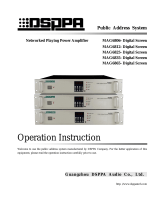
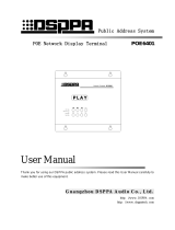
6. Description of Front Panel
1. Power Switch
Press I and O to switch on and off the power source respectively.
2. Power Indicator Light
Indicator light will flash and distinguish respectively when the power is switched on and off.
3. Built-in Monitoring Speaker and Volume Control Knob
Turn the knob clockwise and counterclockwise respectively to increase and decrease the volume.
4. Display Screen / Touchpad
Display screen is for dynamic display of system information and operation of touch screen.
5. Aviation Microphone Volume Control Knob
It is used to control volume of microphone on the front control panel, which can be turned clockwise and
counterclockwise to increase and decrease the volume respectively.
6. Microphone Interface
Signal of the microphone as connected to this interface has the ultimate priority, which can cover all output
signals.
7. USB Interface
It is connected with such memorizers as USB stored with MP3 programs and mobile HD for copying of
programs to MP3 player, which is available for plug-in of the mouse with USB plug.
8. Total Alarm Button
It is applicable to send alarm signals to all zones by the system total alarm button. Button indicator light will
flash when the alarm signal is being sent. Button indicator light will extinguish, and the button will spring up
once the button is pressed to switch off the alarm.
9. Microphone Buckle
Be sure to insert the buckle on the back of microphone into this hole when the microphone is not
in use.
Appearance and Functions
1
2
3
4
5
6
7
8
9

* Firefighting/Public Address System Micro Intelligent Mainframe
3
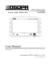
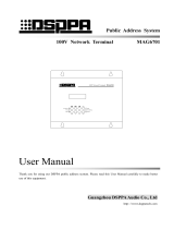
1.Description of Rear Panel
1. 8-route Audio Source Input Interface and Volume Control Knob
8 independent audio source input channels are available for connection with 8 external audio source
equipments. Each channel is provided with one independent volume control knob.
2. 40 Audio Matrix Output Interfaces
Each audio output interface is corresponding to one zone for connection with power amplification audio input
interface.
3. Built-in Radio Volume Regulation Knob
This knob is for mechanical regulation of built-in radio volume.
4. Built-in MP3 volume regulation knob
This knob is for mechanical regulation of volume of built-in MP3.
5. Telephone Paging Volume Control Knob
It is used to control telephone paging output volume.
6. Bell Volume Control Knob
It is used to control built-in bell output volume.
7. External Alarm Signal Input Interface
It can be connected with PB99/8815E (alarm generator) for input of alarm signal into the machine and auto
opening of corresponding zone for alarm. Signal from such interface has level 2 prior function next to that of
aviation microphone on the front panel.
8. Alarm Volume Regulation Knob
It is used to control volume of alarm signal as input by PB99/8815E.
9. Wireless Remote Controlled Receiving Antenna Interface
Connect wireless remote control antenna to this interface. For details, please refer to Description of Wireless
Remote Control Functions.
10. Remote Pager Connection Interface
1
2
3 4 5 6
7
8 9 10
11
12
13
14
15
16
17
18
19
20
21
22

* Firefighting/Public Address System Micro Intelligent Mainframe
4
9-pin D-type data port can be directly connected to remote paging device or paging hub for expansion of
numerous remote pagers.
11. Remote Pager Volume Control Knob
It is available for mechanical control of volume of remote pager.
12. Short-circuit Signal Output Interface
Output short-circuit signals to other equipments to be activated.
13. Zone 1-20 Alarm Signal Input Interface
Input signals from firefighting center.
14. Zone 21-40 Alarm Signal Input Interface
Input signals from firefighting center.
15. Built-in Radio Head Module
For radio head module, please refer to Connection of Radio Head Module.
16. Telephone Interface
IN interface aims to connect telecommunication signals to this machine; whereas OUT interface is expected to
link up with other telephone sets.
17. Radio Signal Input Interface
TUNER OUT interface as connected with radio head module aims to input radio signals to the machine for
play of radio audio sources.
18. Network Interface
It is connected with LAN for remote control of the system.
19. Data Interface
It is for timed control of external audio sources, which is connected with data exchange interface with external
audio sources.
20. Timed Power Output Socket
It provides AC 220V working power supply to external equipments for control output status via the timing
points.
21. AC Fuse Holder
Please use fuse of the same specification to replace damaged one. There might be line faults to the machine in
case of continuous blowout of fuse. Be sure to check the line, and use fuse of the same specification to replace
the damaged one once the fault is recovered.
22 AC220V Power Input Faucet
This interface is used for switch-in of working power supply to the machine. Be sure insert the plug before
connection with power grid in case of connection.

* Firefighting/Public Address System Micro Intelligent Mainframe
5
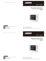
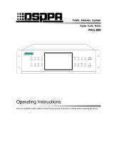
2. Input Connection Description(Audio sources as indicated in the following figure is for illustration
only; any user may proceed with connection at his or her discretion.)
3. Description of Output Connection
This machine is expected to distribute 8 external audio sources and 2 built-in ones to 40 audio output ports for
output to 40 zones. Each zone is provided with one set of power amplifier to receive audio signals from this
machine. Refer to the following figure.
8-route audio source input interface is on the left upside of the rear panel
Audio source 2 PC
Audio source 5 AUX1
Audio source 1 CD
Audio source 7,
external MP3
Audio source 3 VCD
Audio source 8, external
radio
Audio source 4 DVD
PA in Zone 1
PA in Zone 11
40 output ports connected with power
amplifiers in zone 1-40
PA in Zone 40
PA in Zone 30
Audio source 6 AUX2

* Firefighting/Public Address System Micro Intelligent Mainframe
6
4. Other Connections
Description:
Make sure that placement of wireless receiving antenna is close to the receiving orientation of wireless
remote controller to obtain more satisfactory receiving effect and longer receiving distance.
D-type port is available for direct connection with remote pager or paging hub for expansion of
numerous remote pagers.
5. Connection of Radio Module
Radio function of this machine is realized by the module, which is available for separation. It is applicable
to place radio module at the position of strong receiving signals for connection with extended network line
so as to ensure effective improvement of receiving effect. Radio module is connected with this machine with
T586 network line. Module as installed on this machine is also available for butt joint on the rear panel
through network line.
Prompt: Please fabricate extended connecting line in reference to the following figure if radio module
is to be disconnected:
Wireless Remote Control
Receiving Antenna
Firefighting Center
Telephone signals from
telecommunication
office
Network
Control external audio
source interface
Paging Hub
Remote Pager 1
Remote Pager 10
Remote Pager
Or available for direct
connection

* Firefighting/Public Address System Micro Intelligent Mainframe
7
Radio connection mode is as shown in the following figure.
① Connection mode for installation of radio module on the machine.
② Connection mode for radio module not installed on the machine.
RJ45 interface
Colors for left-right connection
Green-white, green, orange-white and blue
Blue-white, orange, brown-white, brown;
both ends in one-to-one correspondence
Pinch cock
opposite to
you
Pin 1
TUNER IN
TUNER OUT
FM Antenna
AM Antenna
TUNER OUT
TUNER IN
Insert connecting
wire into the
hole
Release the
wire clip
cap
Press down
wire clip cap
FM Antenna
AM Antenna

* Firefighting/Public Address System Micro Intelligent Mainframe
8
1.
Main Interface
Start in process, please wait” will be displayed on the screen once the power is switched on to start the machine.. It is
applicable to enter the main interface as shown in the following figure after start-up.
As shown in the aforesaid figure, information as displayed on the main interface include 10 audio sources, current
time, status and operation of 40 zones, power output control status and operation, programmed/manual control setting,
monitoring setting, timing program selection and system access setting.
1) Distribution of external audio sources
Enter the main interface to play programs in corresponding zones. Firstly, select corresponding audio source for
distribution to the zone where it is to be played. Specific operation is stated as follows: Select audio source to be
displayed in “audio source zone” (if CH4 audio source is selected, audio source button will be sunken; whereas red
color showing selected audio source is to be displayed). After that, click the zone where the audio source is to be
played. It will be available for play once zone button is in green color, and audio source is displayed.
Prompt: Be sure to make sure that programs are being played by the external audio source to be distributed to the
corresponding zone or switch such audio source to the play status after distribution. Caution: Audio source selection
will be invalid if current zone is at paging, warning, call or aviation microphone paging status.
2) Distribution of Built-in Audio Source
CH9 and CH10 in audio source zone belong to built-in audio sources. Each built-in audio source is provided with a
player that can be turned on directly for setting of play status. Click the audio source button (such as CH9 button) to
enter the play status operation interface (as shown in the following figure, random setting of MP3 programs to be
played is available in the play interface) during operation.
Operation Instructions
(Figure 1) Main Interface
10
audio
source
buttons
Current time
and date
display zone

* Firefighting/Public Address System Micro Intelligent Mainframe
9
Select catalog (such as “common comity”) in the “Song Catalog” on the left side for play. Songs in the catalog will be
displayed in the playlist on the right side. After that, proceed with setting of play mode (such as “loop play”) in the
“mode selection” on the left corner of the interface before clicking “play” button to play. Click “back” to return to the
main interface after play, and then click corresponding zone directly to distribute MP3 audio source to the zone where
such audio source is to be played. Distribution mode for radio audio source is identical to that of MP3 audio source.
It is applicable to enter the radio play interface to select play status once “radio” audio source is selected. As shown in
the following figure, radio play operations include band switching, radio station searching and storage as well as mute
setting. Note: Ensure correct connection of radio module on the rear panel of the machine.
(Figure 2) Main Interface
(Figure 3) TUNER

* Firefighting/Public Address System Micro Intelligent Mainframe
10
① Band switching: As shown in the aforesaid figure, “BAND” on the interface is used for band switching. It is
applicable to click this button for switching between AM and FM. Frequency band of AM and FM is
522kHz-1620kHz and 87.00MHz-108.00MHz respectively.
② Radio station searching: Click “AUTO” to select radio stations before clicking for forward
and backward auto searching. Searching will come to a stop once any station is discovered.
③ Station memory: Any station as searched is available for numbered memory to facilitate timing control and
further use. AM and FM are provided with 40 memory numbers respectively for storage of 40 station
channels. Once any station is searched, click “MEMO” to change the button into orange color, and then push
the to select memory number. Once corresponding memory number is selected, click
“MEMO” again to change the button into white color to complete station memory.
④ Mute: As shown in the aforesaid figure, the button will be in orange color once the “MUTE” is clicked.
Meanwhile, speaker icon at the right upper corner will be switched to the status as shown in the figure. This
indicates that radio is switched to mute mode. The button will be in white color again if “MUTE” is clicked
to cancel the mute mode.
3) Zone Switch Operation
Zone switch is available for both individual and synchronous control. As shown in the main interface, only zone 1-20
are displayed on the interface. It is necessary to use page rolling button (as shown in the following figure) for display
of zone 21-40.
Click zoning button directly for switching operation. The button will be in white and green colors respectively when
corresponding zone is closed and opened. Furthermore, audio source for the said zone will also be displayed on the
zoning button. It is also applicable to proceed with overall synchronous operation of the zone. Operation button is as
shown in the aforesaid figure.
4) Output power source
As shown in the aforesaid figure, PWR1 and PWR 2 are control buttons for output power 1 and 2 respectively. It is
Zone
on/off
control
button
Page rolling button
Programmed/manual control
switching button
Output
power
control
button
(Figure 1) Main Interface

* Firefighting/Public Address System Micro Intelligent Mainframe
11
applicable to proceed with switching control of output power by clicking such buttons directly. Output power is also
available for auto timing control.
5) Programmed / manual switching
As shown in the aforesaid figure, it is applicable to click “programmed/manual control” button directly for switching
between programmed and manual modes.。Note: Be sure to set this button at preset “programmed” timing point
for execution. All timing points will unavailable for execution if such button is in “manual control” mode.
6) Monitoring Setting
This machine is available for monitoring of each zone. Click “monitoring setting” button to enter the monitoring
interface as shown in the following figure in case of operation.
It is applicable to monitor zone status by clicking zone button on the monitoring interface directly. The button will be
in green color when the zone is under monitoring; whereas “×” before the speaker icon will be changed into “√”. Use
“Page Rolling” button to open the display interface for zone 21-4 to be monitored. After that, press zone button for
monitoring.Selection of Timing Program
Press “Timing Program” to enter the timing program Interface as
shown in the following figure. Make sure that timing program has
been stored in the system before selection. The system can store 5
timing programs. Be sure to ensure proper saving of edited timing
program in case of timed editing. Timing program is to be saved in
reference to Timed Programming.
2. System Setting
Click here to
select timing
program on
the dropdown
men
(Figure 4) Monitoring Setting
(Figure 5) Timing Program

* Firefighting/Public Address System Micro Intelligent Mainframe
12
Click “System Setting” on the main interface to enter system setting interface as shown in the following figure:
It is applicable to proceed with setting of overall system information on the system setting interface. Be sure to ensure
proper setting of all options on the system setting interface before play on the main interface. This aims to ensure
accurate execution and operation of various system functions.
1) Timing Setting
Click “Timing Setting” button to enter the timing setting interface as shown in the following figure:
Bell setting: Select
bell signal. No
selection means no
bell
(Figure 6) System Setting
This item is to be selected during
timing point setting; otherwise,
timing point will be invalid
(Figure 7) Timing Setting

* Firefighting/Public Address System Micro Intelligent Mainframe
13
This interface is for editing various functional information on timing points:
① Week selection: This operation aims to select the date of timing points. For instance, it is applicable to select
corresponding date in the block of “Monday-Friday” if timing points are to be executed from Monday to
Friday (“√” in the block represents selected date).
② Designations of timing points: Define designation for edited timing points. For instance, timing point
representing wake-up bell can be defined as “Wake-up”. Open the designation editing buttonboard (click the
functional button of “Alteration” on the right side of timing point designation block) to enter the editing
buttonboard interface (as shown in the following figure). After that, select Chinese or English at the bottom
right corner of the buttonboard. Input timing point, and click the “Confirm” button at the bottom to complete
editing, and exit the buttonboard.
③ Bell selection: There are 3 bell signals available for selection in the system. Click inverted triangular symbol
after the “Bell”, and select bell signal on the dropdown menu. The 3 bell signals are defined as bell 1, 2 and 3
respectively. Click the selected bell for one time to display its designation.
④ Timing time: This setting aims to edit start time of timing points. It is applicable to alter the time by click
black triangular symbol beside the time block. Timing time of the system is accurate to second. Timing to the
second will not be required if not necessary.
⑤ Output power supply control: “PWR1, PWR2” behind the “Timing Time” is used t control switching status
of two-route power supply on the rear control panel. Click corresponding block for one time to select
required power supply status on the dropdown menu to complete setting.
⑥ Completion time: Method for setting of completion time I identical to that for start time. The only difference
is that the system has optional requirement for completion time. In other words, completion time may be
required or not required as per specific demands, which is to be defined as per timing points.
Click here to select
output power supply
status to complete
setting.
Click to select here
before setting of
completion time
Be sure to select English
or Chinese before input
(Figure 8) Timing Point Editing Buttonboard
(Figure 9) Indication of Output Power Supply and Completion Time

* Firefighting/Public Address System Micro Intelligent Mainframe
14
⑦ Program selection: This operation aims to select operative audio source for timing points. Select “Program
Selection” button to enter the program setting interface as shown in Figure (10), (11) and (12). One built-in
timing point is available for timed play control of built-in MP3, built-in radio and 4 external audio sources.
(Figure 10) Setting of Audio Sources for Timing Points
(Figure 11) Setting Audio Sources for Timing Points
Select catalog in
the block, and click
here to open the
item selected
Set wave band and
channel after
selection of play
status.

* Firefighting/Public Address System Micro Intelligent Mainframe
15
As shown in Figure (10), click “Add” button to select catalog when setting built-in MP3 programs (such as
selection of “common comity”). After that, click “Next Catalog” to open the catalog, and select songs to be
played. Once completed, click the “Add” button, and designations of selected songs will appear in the
playlist of “Selected Songs”. It is also applicable delete any song from the playlist of “Selected Songs”.
Specific method is stated as follows: Select the song to be deleted, and click “Del” on the right side.
Select required control status among “Uncontrolled”, “Play” and “Stop” at the bottom right corner of the
interface prior to editing when setting built-in radio programs (as shown in Figure 11). Note: Be sure to set
wave band and channel after selection of play status. Channel number represents the memory number of
station as stored in the radio tuner. Radio function at corresponding timing point will be invalid if the
selected memory number is not stored with any station.
Setting of external audio sources involves the following operations: Selection of audio equipment types,
control modes (play or stop) and programs. Click “Add” to add the audio source into the list of “Controlled
Equipments” once any equipment (such as holder) to be controlled by the timing point is selected. It is also
applicable to delete any uncontrolled equipment from the list (as shown in Figure 12).
Click “Return” button at the bottom to exit the audio source setting interface once all items are set.
(Figure 12) Setting of Audio Sources for Timing Points
⑧ Zone selection: Click “Zone Selection” button on the timing setting interface to enter the zone selection
interface as shown in the following figure (Figure 13).
Any timing point in this system can control play status of 6 audio sources. The 6 audio sources is available
for free selection in the corresponding zone. In other words, all zones at one timing point can play different
programs.
Firstly, select audio sources to be distributed to corresponding zone in case of setting. For instance, it is
necessary to select “external radio” audio source, and click buttons in zone 1-10 if external radio is to be
distributed to zone 1-10. Under such circumstance, corresponding button will be in green color to display
“external radio”. If all audio sources subjecting to timing control are to be distributed to corresponding
timing control zone, just click “Back” to exit the interface to complete timing setting of corresponding
zone .
Click this button to add
equipment as set into the list of
controlled equipments

* Firefighting/Public Address System Micro Intelligent Mainframe
16
(Figure 13)
⑨ Once items for timing points are set, click “Add” to add such items into the timing list.
⑩ Deletion of timing points: Timing points can be deleted by clicking individual and whole deletion buttons.
“Del” aims to delete certain selected timing point in the timing list; whereas “Delete All” is expected to
delete all timing points.
⑪ Saving of timing points: Click “Add” to save one timing point as edited in the system. After that, click
“Back” to exit the timing point setting interface.
2) Program Setting
Click “Program Setting” on the “System Setting” interface to enter the setting interface as shown in the following
figure (Figure 14):
Figure 14

* Firefighting/Public Address System Micro Intelligent Mainframe
17
“Program Setting” for system setting aims to edit music library of built-in MP3, including browse, copy and deletion
of songs. As shown in the aforesaid figure, once certain catalog in the catalog block on the right side is selected, all
songs in it will be displayed in the central program block. Once programs in such block are selected, it will be
applicable to proceed with deletion operation by using deletion button at the bottom of the interface.
Block on the right side of the interface aims to display programs in the USB on the front panel. Once song
designations are directly displayed in this block, it will be applicable to select relevant songs. After that, click
“Individual Copy” button below the block to copy selected songs into the machine. In the event that catalog is
displayed in the block below “USB Device”, just select certain catalog, and click “Next Catalog” below the block to
enter the playlist before copy programs.
If catalog is displayed in the block below “USB Device”, just select this catalog, and click “Copy all” to copy all
songs in this catalog into the machine.
Note: As music library of the system is only provided with one catalog, any song under the catalog additionally
established is unavailable for play. Therefore, never copy songs to the system music library when copying
programs.
3) Nomination of Audio Sources
Click “Audio Source Setting” on the “System Setting” interface to enter the audio source setting interface as shown in
the following figure (Figure 15):
(Figure 15)
It is applicable to alter or nominate designation of each audio source on this interface. Click the block displaying
designation of audio source to select certain audio source (such as CH2), and then click “Alteration” after it to open
the input buttonboard. Input designation of the audio source on the buttonboard, and click “Confirm” button to
complete nomination of audio source. Once completed, push the “Confirm” button again to return to the system
setting interface.
4) Monitoring Setting
Click “Monitoring Setting” button on the “System Setting” interface to enter the zone monitoring interface.
Monitoring mode here is identical to that on the main interface. For more details, please refer to “Monitoring Setting”
on Main Interface during operation.
5) Wireless Process Setting
Click “Wireless Process Setting” button on “System Setting” interface to enter wireless process setting interface as
shown in the following figure (Figure 16). This system can be controlled with wireless controller in the control mode
identical to that for timing points. Remote control distance of wireless remote controller ranges from 100m to 1000m
as per different environments. Be sure to properly set certain functional operation of certain button on the wireless

* Firefighting/Public Address System Micro Intelligent Mainframe
18
remote controller for control of this system in advance. Thus, once this button is pressed, the system will
automatically execute preset functional operation.
Select certain remote control number (such as remote control number 1) among the “process serial numbers” on the
left side in case of setting. After that, set control items in the functional setting block on the right side. For instance, if
remote control number 1 is to be selected to control play of audio source :CH1” in zone 1-10, just click “Zone
Selection” button to enter zone selection interface after selection of “remote control number 1”. Distribute audio
source “CH1” to zone 1-10 as per audio source distribution mode on the interface before exiting the interface. If
“remote control number 1” is requested to control play status of audio source, just enter the “Audio Source Setting”
interface to proceed with various settings of audio source. Setting mode is identical to that for setting of audio sources
for timing points. “Remote Control Number 1” is also available for simultaneous control of status of output power
supply and bell.
Prompt: One button of wireless remote controller is capable of controlling one or numerous functions of this system.
However, all controls should be set here in advance. Operation for selection of zones and programs is identical to that
for timing points, which shall not be described herein.
6) Alarm Setting
Click “Alarm Setting” button on the “System Setting” interface to enter alarm setting interface as shown in the
following figure (Figure 17). It is applicable to set alarm zone linkage, alarm audio source and alarm triggering level
on this interface.
Be sure to properly set “Alarm Audio Source Setting” and “Alarm Level” below this interface in case of setting. After
that, select one certain alarm channel (such as CHN1) in the “Alarm Channel” block on the left side. Once completed,
select alarm zone to be triggered by CH1 in the “Triggering Zone Setting” on the right side. It is applicable to select
single or all zones or cancel the selection.
If “Alarm Time” is not selected, the system will initiate internal alarm whistle as alarm signal when external alarm
audio source is actuated for alarm. If such option is selected, just use externally input alarm signal in priority instead
of using internal alarm whistle in case of alarm. Make sure that external alarm equipment has been properly connected
under such circumstance.
(Figure 16) Wireless Process Setting
/