
RP/IS-994/994RPDA
NOTICE
Inquire with governing authorities for local installation requirements
NOTICE
For Australia and New Zealand: Pipeline strainers should be installed
between the upstream shutoff valve and the inlet of the backflow
preventer.
994
Installation, Maintenance, & Repair
Series 994/994RPDA
Reduced Pressure Zone Assemblies
Reduced Pressure Detector Assemblies
Sizes: 2
1
⁄2" – 10" (65 – 250mm)
Local building or plumbing codes may require modifications to the
information provided. You are required to consult the local building and
plumbing codes prior to installation. If this information is not consistent
with local building or plumbing codes, the local codes should be fol-
lowed.
Need for Periodic Inspection/Maintenance: This product must be
tested periodically in compliance with local codes, but at least once per
year or more as service conditions warrant. Corrosive water conditions,
and/or unauthorized adjustments or repair could render the product
ineffective for the service intended. Regular checking and cleaning of the
product’s internal components helps assure maximum life and proper
product function.
WARNING
!
Read this Manual BEFORE using this equipment.
Failure to read and follow all safety and use information
can result in death, serious personal injury, property
damage, or damage to the equipment.
Keep this Manual for future reference.
Testing
For field testing procedure, refer to Watts installation sheets
IS-TK-DP/DL, IS-TK-9A, IS-TK-99E and IS-TK-99D found on
www.watts.com.
For troubleshooting guide, refer to literature S-TSG.
For other repair kits and service parts, refer to our Backflow Preven-
tion Products Repair Kits & Service Parts price list PL-RP-BPD
found on www.watts.com.
For technical assistance, contact your local Watts representative.

2
Location and Installation Considerations
1. Backflow preventers must be installed in high-visibility lo ca tions in
order to allow for immediate notice of telltale discharge or oth er
mal func tion. This location should also facilitate testing and ser vic-
ing and protect against freezing and vandalism.
2. Installation procedures must comply with all state and lo cal
codes.
3. Installing a backflow preventer in a pit or vault is not rec om mend-
ed. An air gap be low the relief port must be maintained so as to
avoid flood ing and sub mer sion of the assembly, which may lead
to a cross-connection. Watts recommends installations in doors
or above ground in an in su lat ed enclosure. (Refer to literature
ES-WB)
4. A strainer should be installed ahead of the backflow pre ven ter to
protect the discs from unnecessary fouling.
CAUTION
!
Do not install a strainer ahead of the backflow pre ven ter on
seldom-used, emergency water lines (i.e. fire sprinkler lines). The
strainer mesh could potentially become clogged with debris pres-
ent in the water and cause water blockage during an emer gen cy.
5. Normal discharge and nuisance spitting are ac com mo dat ed by
the use of a Watts air gap fitting and a fabricated indirect waste
line. Floor drains of the same size MUST be provided in case of
ex ces sive discharge.
6. When a Series 994 backflow preventer is installed for dead-end
ser vice applications, dis charge from the relief vent may occur
due to wa ter supply pressure fluc tu a tion during static no-flow
con di tions. A check valve may be re quired ahead of the backflow
preventer.
7. ASSEMBLY: If the backflow preventer is disassembled dur ing
in stal la tion, it MUST be reassembled in its proper order. The gate
valve with the test cock is to mounted on the inlet side of the
back flow pre ven ter. The test cock must be on the inlet side of the
wedge. Failure to reassemble correctly will result in possible wa ter
damage due to excessive discharge from the relief port/vent and
possible mal func tion of the backflow preventer.
8. Prior to installation, thoroughly flush pipe line to re move any for-
eign matter.
9. START UP at Initial Installations and After Servicing: The down-
stream shutoff should be closed. Slowly open upstream shutoff
and allow the backflow preventer to fill slowly. Bleed air at each
test cock. When backflow preventer is filled, slowly open the
down stream shut off and fill the water supply system. This is nec-
es sary to avoid water hammer or shock damage.
NOTICE
Assembly body should not be painted.
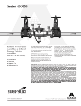
Figure 1
VALVE SIZE
TYPICAL FLOW RATES AS
SIZED BY FLOOR DRAIN
MANUFACTURERS
DRAIN SIZE
in. mm
2
1
⁄2 65 55 gpm 2
3 80 112 gpm 3
4 100 170 gpm 4
6, 8, 10 150, 200, 250 350 gpm 5
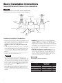
Basic Installation Instructions
Series 994 Reduced Pressure Zone Assemblies
#2 Test Cock
#3 Test Cock
#4 Test Cock
Outlet
Shutoff
#2 Check
Relief
Valve
Sensing
Line
1st Check
#1 Test Cock
Inlet Shutoff
Valve
NOTICE
The flange gasket bolts for the gate valves should be re tight ened during
in stal la tion as the bolts may have loos ened due to storage and ship ping.

3
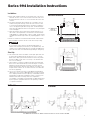
Series 994 Installation Instructions
*For additional information on Watts insulated enclosures refer to literature ES-WB.
Parallel
Indoors
Above Ground
12” (300mm) min.
Refer to
Local Codes
Strainer
12” (300mm) min.
Refer to
Local Codes
12” (300mm) min.
Refer to Local Codes
*Insulated Enclosure
Installation
A. Series 994 shall be installed in a horizontal po si tion. The shutoff
valve with the test cock is to be mounted on the inlet side of the
back flow pre ven ter. The test cock is on the in let side of the shut-
off valve.
B. The 994 should always be installed in an ac ces si ble lo ca tion to
fa cil i tate test ing and ser vic ing. Check the state and local codes
to en sure that the back flow pre ven ter is installed in com pli ance,
such as the prop er height above the ground. The back flow pre-
venter must be sup port ed and is not de signed to car ry full weight
of the stand pipe.
C. Water discharge from the relief valve should be vented in ac cor-
dance with code re quire ments. The relief valve should never be
sol id ly piped into a drain age ditch, sew er or sump. The dis charge
should be funneled through a Watts air gap fitting piped to a floor
drain.
D. Watts recommends a strainer be in stalled ahead of Watts Series
994 as sem blies to pro tect the discs from un nec es sary foul ing.
CAUTION
!
Do not install a strainer ahead of the backflow pre ven ter on
seldom-used, emergency water lines (i.e. fire sprinkler lines). The
strainer mesh could potentially become clogged with debris pres-
ent in the water and cause water blockage during an emer gen cy.
Start Up
E. The downstream shutoff should be closed. Open up stream slow-
ly, fill the valve and bleed the air through Test cock 2, 3 and 4.
When valve is filled, open the down stream shutoff slowly and fill
the wa ter sup ply sys tem. This is nec es sary to avoid wa ter ham-
mer or shock dam age.
F. The installation of a Watts air gap with the drain line ter mi nat ing
above a floor drain will handle any normal dis charge or nuisance
spit ting through the relief valve. How ev er, floor drain size may
need to be de signed to pre vent water damage caused by a cat a-
stroph ic fail ure con di tion. Do not reduce the size of the drain line
from the air gap fit ting.
G. Two or more smaller size valves can be piped in parallel (when
ap proved) to serve a large supply pipe main. This type of in stal la-
tion is employed where in crease capacity is needed be yond that
pro vid ed by a single valve and per mits test ing or ser vic ing of an
in di vid u al valve with out shut ting down the com plete line.
The number of assemblies used in par al lel should be de ter mined
by the en gi neer’s judge ment based on the op er at ing conditions
of a spe cif ic in stal la tion.
994
994
994

4
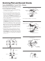
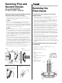
Servicing First and Second Checks
Series 994/994RPDA 4" and 6" (100 – 150mm)
Removing Check Assemblies (Before servicing
be sure shutoff valves are closed)
Figure 3
Figure 2
Figure 4
B
A
C
Screwdriver
#2 Check
#1 Check
#1 Check 2
1
⁄2
"
– 6" (65 – 150mm)
Spring
Cam Arm
Roller
Clapper
Seat
O-ring Seal &
Groove
#2 Check
Spring
Cam Arm
Roller
6” Only
Clapper
O-ring Seal & Groove
Seat
Lug
O-ring Seal & Groove
Figure 5A
6" (150mm)
2nd Check RP
Valve Outlet Flange Threaded
Stud on Flange
Cam Bar Open Pin
Figure 5B
Cleaning Position
1. Slowly open all ball valves to relieve air and water pressure.
Loosen bolts on groove coupler and remove groove couple
and cover plate from valve body.
2. Remove #1 Check Assembly by using your hands to un screw
(turn counterclockwise) Check and remove through top access
port. Do not use Check Arm as a handle to unscrew. If Check
can not be loosened by hand, insert a long screwdriver between
valve body and Check (see figure 2). Gently apply pressure
against the Check until loos ened. Fin ish unscrewing by hand. Un-
screw #2 Check (turn counter-clock wise) by placing along screw-
driv er across lugs and applying pres sure to loosen #2 Check.
Fin ish un screw ing by hand.
3. To clean #1 Check 6" (150mm) only, locate the Check Arm
opening stud on the outlet flange of the valve assembly. Slide the
Check Arm over the stud with the check threads facing down-
ward (figure 5A). Tighten
1
/4" (8mm) nut on stud to secure cam
bar. Slowly pull the assembly outward to open check allowing ex-
posure of the seat clapper area for clean ing. To clean #2 Check,
lift Cam Arm and hold in open po si tion. Raise clapper so that the
end of the Check Arm rests between roller and clapper (fig ure
5B). Thoroughly clean the seat area and clapper sealing sur fac es
of both Checks. In spect seats, clap per sealing surfaces, Check
Arms, and O-rings for damage, nicks, and debris. If not dam-
aged, gently close the clap per. If damaged, install a new Check
assembly and/or O-ring.
4. Before reinstallation of Checks, thoroughly clean O-ring groove
and lubricate O-ring with FDA approved lubricant. Insert and
thread #2 Check first and then #1 Check. #2 Check should be
tightened by in sert ing a long screwdriver between lugs to tighten
firm ly (see fig ure 2). Do not over tighten. Tighten #1 Check firmly
by hand only. Replace cover plate, clean groove coupler gas ket
and groove. Replace groove coupler. Repres-surize and bleed air
from all test cocks.
Figure 1
7
Note: See page 6 for additional 1
st
check servicing

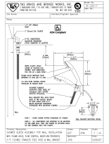
5
Servicing First and
Second Checks
Series 994/994RPDA
8" and 10" (200 – 250mm)
1. Slowly open all ball valves to relieve air and water pressure.
Loosen bolts on groove coupler and remove groove couple and
cover plate from valve body.
2. #1 CHECK
Using a
9
⁄16" socket wrench or nut driver, remove the four nuts
from the #1 check studs (see fig. 1). Using two hands, place
them at 12 o’clock and 6 o’clock, wiggle the check assembly free.
Remove through access port with back of clapper first with spring
end down. Pull check assembly out of main body. Inspect seats
and clap per seal ing surfaces. (See page 6.)
#2 CHECK
After loosening bolts with a
9
⁄16" socket, remove bolts completely.
Using the centerline access bar, spin the check assembly from the
9 o’clock position to the 12 o’clock position, then (without letting
go of the ac cess bar) push the cam assembly slightly down stream
so that the clapper is now parallel to the valve body. Now bring
the check as sem bly through the check retaining wall. Leave the
check assembly par al lel to the valve body. Pull the check assem-
bly through the access port.
3. Using a
3
⁄8" nut driver or a piece of small diameter pipe, place
on the check arm torsion spring and move away from and move
away from and around the torsion spring retaining bracket so as
to relieve the tor sion spring tension. This will allow the check arm
to move free ly, en abling you to inspect the clapper face and check
seat. Thor ough ly clean the seat area and clapper sealing surfaces,
check arms, and O-rings for damage, nicks, and debris. If dam-
aged, in stall a new check as sem bly and or O-ring.
4. Before reinstallation of check assembly, thoroughly clean O-ring
groove and lubricate O-ring with F.D.A. approved lubricant.
Figure 1
Check Studs
Check Studs
Figure 3
#2 Cam-Check DC & RP
Figure 2
#1 Cam-Check RP
Figure 4
Removing Check Assemblies (Before servicing
be certain shutoff valves are closed)
1. After removing the first check from the backflow valve body, place
on a flat surface with the coil spring facing up.
2. In order to gain access to the seat and clapper rubber ring, you
must compress the spring (#3) that surrounds the clapper shaft
(#1). To do so, you must place the
3
⁄8" threaded rod through two
holes of the spring retaining plate #2.
3. After placing the
3
⁄8” all-thread rod through the spring retaining
plate, Screw the threaded rod into the holes (#4) at the base of
spider (#5 next to shaft). Be sure to use two nuts on the threaded
rod to tighten them into the holes. The depth of the threaded
holes should be approximately
1
⁄2". This operation will require you
to use two piec es of threaded rod (see drawing below).
4. Compressing the spring. To do so you need to loosen the top
3
⁄8”
nut and back it off without unthreading the threaded rod from the
spider. Place a box end wrench or crescent wrench on the
3
⁄8”
nut clos est to the spring retaining plate and tighten. Tighten both
thread ed and nut evenly; put a few turns on one threaded rod nut
and a few turns on the other.
5. During compression, the clapper will slowly move up, away from
the seat. To examine the seat, continue spring compression un til
the clapper has moved approximately 1" from the seat. This will
allow de bris to be removed and or the seat to be examined.
6. To unload the spring compression, loosen the all-thread and then
double nut the all-thread and unscrew the rod from the spider and
shaft base.
1. Shaft
2. Spring retaining plate
3. Spring
4.
3
⁄8” threaded hole (maintenance)
5. Spider
6. Spider retaining bolt
7. Seat ring
8. Clapper to shaft bolt
9. Seat ring retainer
1
2
3
4
5
6
3
⁄8 - 16
var.
Threaded Rod
7
8
9
#1 Check
Valve 8" & 10"
(200 & 250mm)
DANGER
!
Use extreme caution when servicing the first check!
Servicing the
First Check
To inspect the seat and clean the seat and
clapper washer:
To disassemble the first check, you will need
the following:
•Twopiecesof
3
⁄8" threaded rod (approximately 14" long)
•Adjustablecrescentwrench
•Pipewrenchorchannellockpliers

6
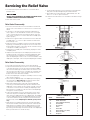
Servicing the Relief Valve
1. The relief valve may be serviced while on or off the backflow
preventer valve.
2.
NOTICE
DO NOT USE A PIPE WRENCH TO REMOVE THE RE LIEF VALVE
ASSEMBLY FROM THE BACKFLOW PREVENTER.
3. Shut down water system.
Relief Valve Disassembly
1. Disconnect the relief valve hose from the elbow in the bottom
flange cover at the swivel hose connection. Do not remove the
el bow.
2. If the valve is to be removed from the backflow preventer for
service, place a screw driver blade or flat bar across the edges
of two of the hex head screws in the bottom flange cover and
turn counter-clock wise to loosen the relief valve assembly. (See
Figure 2 page 4)
3. Remove the four bottom bolts from the bottom of the relief valve
assembly with a
5
⁄16” socket or open-end wrench. Remove the
bottom flange cover.
4. Remove the piston assembly & sleeve from the relief valve body
by placing your index fingers through the slots in the side of the
body and pressing down on the top of the disc retainer in the top
of the piston as sem bly. (See Figure 7.)
5. Pull the piston assembly free of the body by grasping the sleeve
and pulling down.
6. Grip the sleeve and the piston assembly by the head of the hex
head bolt. Pull up on the sleeve to extend the diaphragm. Slide
the sleeve (item #26) completely off of the diaphragm and in-
spect the diaphragm for tears, holes or excessive wrinkles. If the
diaphragm is dam aged, or der a new piston/diaphragm assembly.
Relief Valve Reassembly
1. Thoroughly clean all inside surfaces of the relief valve body.
2. Inspect the relief valve body seat surface located at the top edge
of the three discharge slots near the top of the body by rubbing
the end of the index finger around the entire seat surface; access
the seat sur face through the slots or the bottom of the body. The
seat must be free of nicks. If nicks are discovered, remove the
body & install a new relief valve assembly.
3. Position the diaphragm on the piston assembly so that it is fac ing
up as shown in Figure 8.
4. Now fold the top (ribbed) edge of the diaphragm inward, grasp
the sleeve with the ribbed edge up and slide the sleeve down
over the piston assembly as shown in Figure 8.
5. While still holding the sleeve, slide it up over the diaphragm
and, using your thumb & index finger, position the bead of the
diaphragm so that it wraps over the outside of the rib on the top
of the sleeve so that the sleeve is held by the diaphragm. Now
place the pis ton as sem bly on a flat, firm surface with diaphragm
facing up as shown in Figure 9.
6. Cup your hand slightly to form an air trap and force the sleeve
down over the piston assembly with a rapid slap (hard) on the
open end of the diaphragm with your cupped hand. The trapped
air in the di a phragm will force the diaphragm between the inside
of the sleeve and the out side of the piston. Ensure that the dia-
phragm is fully seat ed. If di a phragm is wrinkled, repeat previous
step.
7. Slide the piston assembly and sleeve into the relief valve body
with the hex head bolt entering the flanged end of the body first.
Slide the piston assembly in until the diaphragm lip is smoothly
seated in the ma chined groove in the flanged end of the body.
By running your in dex finger around the outside of the diaphragm
bead, you will ensure it is seated smoothly
Item # Part Description Qty.
21 Relief Valve Body 1
22 Rubber Shutoff Disc 1
23 Piston Diaphragm Assembly 1
24 Hex Head Bolt 4
25 Disc Retainer 1
26 Sleeve 1
27 Bottom Bolt 1
28 Bottom Flange (w st. elbow) 1
29 Bottom st. elbow 1
30 O-ring disc 1
PARTS TABLE #2
Figure 6
27
21
22
23
24
25
26
28
29
30
Figure 7
Figure 8
Figure 9
8. Position the bottom flange cover on the bottom of the relief valve
body and secure by hand tightening the four bottom bolts.
9. Now tighten the four bottom bolts to approximately 15 ft.-lbs.
with a
5
/16" socket or open-end wrench.
10. Reattach the relief valve hose to the elbow in the bottom flange
cover.

7
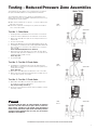
Testing - Reduced Pressure Zone Assemblies
Watts TK-DL
The following Test Procedure is one of several that is recognized
throughout the United States for testing Backflow Preventers.
The following procedure is not a specific recommendation. The
Watts series of test kits are capable of performing any of the recog-
nized Backflow test procedures.
For additional testing information refer to literature IS-TK-DL, IS-TK-9A and IS-TK-99E
A. Open TC #4 and flush test cocks No’s. 1, 2 and 3 on BF assem-
bly, then close TC #4.
B. Turn tester on (before connecting hoses). Tester must read all
zeros. Close VA and VB.
Test No. 1 - Relief Valve
1. Install high-side hose between TC #2 and tester connection A.
2. Install low-side hose between TC #3 and tester con nec tion B.
3. Open TC #3 then VB. Now open TC #2 slowly, then VA. Close
VA then VB.
4. Close #2 shutoff valve.
5. Observe the apparent first check valve differential pressure (A - B).
6. Install bypass hose between VA and VB. Open VB and bleed air
by loosening hose connection at VA. Tighten hose connection
and close VB.
Push - Print Head (wait) then Push - Start Test
7. Open VA, then slowly open VB (no more than 1⁄4 turn). When
relief valve drips, push the “hold button” for 2 seconds. Record
reading (must be 2 PSID or more).
Push - Stop Test
8. Close VA and VB.
Test No. 2 - Test No. 2 Check Valve
9. Install bypass hose between VA and TC #4. Open VA, then
bleed air by loosening hose connection at TC #4. Tighten hose
connection. Close VA.
Push - Start Test
10. Open VB to reestablish pressure within the “zone”. Close VB.
11. Open TC #4, then open VA. If relief valve does not drip, record
second check valve as “close tight”.
Test No. 3 - Test No. 1 Check Valve
12. Open VB to reestablish first check valve dif fer en tial pressure.
Close VB. Record pressure differential.
Stop Test (Push Stop Test twice)
13. Close test cocks and remove tester, return as sem bly to nor mal
operating condition.
RPZ
Test 1
RPZ
Test 2
RPZ
Test 3
Series 994
A
B
VA
VB
WARNING
!
It is important that this device be tested periodically in com pli ance
with local codes, but at least once per year or more as ser vice con-
di tions warrant. If installed on a fire sprinkler system all me chan i cal
checks, such as alarm checks, single checks and backflow preventers
should be inspected internally every one to five years in accordance
with NFPA 13 A and NFPA 25
Series 994
Series 994
A
B
VA
VB
A
B
VA
VB

Problem Cause Solution
A. Assembly discharges
from differential relief
valve during no flow
condition.
Fouled first check Disassemble and clean No. 1
check valve
Fluctuating inlet pressure Control supply line water
pressure.
Install a soft seated, spring
loaded, check valve up-
stream of the assembly.
Outlet pressure higher than
inlet pressure & leak in No. 2
check valve
Disassemble, clean #2 check
valve & identify cause of
backpressure
Leak through diaphragm or
around flange bolt holes of
relief valve
Service relief valve
Pressure relief valve does not
close
See problem D
B. Assembly discharges
from differential relief
valve during a flow
condition.
No. 1 check valve wedged
open
Disassemble and clean No. 1
check valve
O-ring displaced from groove
in 1st check
Disassemble and replace
Pressure relief valve does not
close
See problem D
Fluctuating line pressure
C. Differential pressure
relief valve does not
open during test
Differential pressure across
No. 1 check valve stays above
2.0psi due to leaking outlet
gate valve
Repair shutoff valves
Weak or broken relief valve
spring
Disassemble and replace
relief valve spring
Shutoff seat tube bound in
body
Disassemble and repair
Plugged hydraulic hose Disassemble and repair
D. Pressure relief valve
does not close
Debris on sealing surface Remove relief valve and clean
Plugged hydraulic hose Disassemble and clean
Damaged seat or rubber
shutoff disc
Remove relief valve assembly
and replace
Ruptured diaphragm Disassemble and replace
diaphragm
Wrinkled or improperly in-
stalled diaphragm
Disassemble and properly
position diaphragm
Troubleshooting Guide
Air Gap Drain
11
3
⁄4
7.00
2” Pipe
Thread
RP-IS-994/994RPDA 1319 EDP# 1915230 © 2013 Watts
USA:Tel:(978)688-1811•Fax:(978)794-1848•www.watts.com
Canada: Tel:(905)332-4090•Fax:(905)332-7068•www.watts.ca
Limited Warranty: Watts Regulator Co. (the “Company”) warrants each product to be free from defects in material and workmanship under normal usage for a period of one year from the date of
original shipment. In the event of such defects within the warranty period, the Company will, at its option, replace or recondition the product without charge.
THE WARRANTY SET FORTH HEREIN IS GIVEN EXPRESSLY AND IS THE ONLY WARRANTY GIVEN BY THE COMPANY WITH RESPECT TO THE PRODUCT. THE COMPANY MAKES NO OTHER
WARRANTIES, EXPRESS OR IMPLIED. THE COMPANY HEREBY SPECIFICALLY DISCLAIMS ALL OTHER WARRANTIES, EXPRESS OR IMPLIED, INCLUDING BUT NOT LIMITED TO THE IMPLIED
WARRANTIES OF MERCHANTABILITY AND FITNESS FOR A PARTICULAR PURPOSE.
The remedy described in the first paragraph of this warranty shall constitute the sole and exclusive remedy for breach of warranty, and the Company shall not be responsible for any incidental, special
or consequential damages, including without limitation, lost profits or the cost of repairing or replacing other property which is damaged if this product does not work properly, other costs resulting
from labor charges, delays, vandalism, negligence, fouling caused by foreign material, damage from adverse water conditions, chemical, or any other circumstances over which the Company has no
control. This warranty shall be invalidated by any abuse, misuse, misapplication, improper installation or improper maintenance or alteration of the product.
Some States do not allow limitations on how long an implied warranty lasts, and some States do not allow the exclusion or limitation of incidental or consequential damages. Therefore the above
limitations may not apply to you. This Limited Warranty gives you specific legal rights, and you may have other rights that vary from State to State. You should consult applicable state laws to
determine your rights. SO FAR AS IS CONSISTENT WITH APPLICABLE STATE LAW, ANY IMPLIED WARRANTIES THAT MAY NOT BE DISCLAIMED, INCLUDING THE IMPLIED WARRANTIES OF
MERCHANTABILITY AND FITNESS FOR A PARTICULAR PURPOSE, ARE LIMITED IN DURATION TO ONE YEAR FROM THE DATE OF ORIGINAL SHIPMENT.
A Watts Water Technologies Company
WARNING: This product contains chemicals known to the
State of California to cause cancer and birth defects or
other reproductive harm.
For more information: www.watts.com/prop65
For repair kits and parts, refer to our
Backflow Prevention Products Repair
Kits & Service Parts price list PL-RP-BPD
found on www.watts.com.
-
 1
1
-
 2
2
-
 3
3
-
 4
4
-
 5
5
-
 6
6
-
 7
7
-
 8
8


Ask a question and I''ll find the answer in the document
Finding information in a document is now easier with AI
Related papers
-
Watts 912HP 1 Installation guide
-
-
Watts 4000SS-LG 10 Installation guide
-
-
-
Ames Fire & Waterworks ATG-1 Installation guide
-
Febco TK-1 Installation guide
-
Watts 919-QT-SH 2 Installation guide
-
-
Other documents
-
 T & S Brass & Bronze Works B-0917 Datasheet
-
Dwyer Series BTK User manual
-
 Watts Industries AMES Silver Bullet 4000SS Series Installation guide
-
SPT 20099 Installation guide
-
Rain Bird HVF Installation guide
-
Ames Fire & Waterworks LFM300,M200,M300 Installation guide
-
Generic WVPOLSET Product information
-
Ames Fire & Waterworks 0690471 Installation guide
-
Ames SILVER BULLET 2000SS Series User manual
-
 Dormont Mfg C500 Installation guide


