Page is loading ...

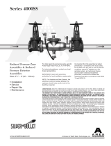
Double Check Valve
Assemblies & Double
Check Detector
Assemblies
Sizes: 8" – 12" (200-300mm)
• Installation
• Service
• Repair Kits
• Maintenance
IMPORTANT: Inquire with governing
authorities for local installation requirements.
NOTE: For Australia and New Zealand, line
strainers should be installed between the
upstream shutoff valve and the inlet of the
backflow preventer.
but at least once per year or more as service
conditions warrant. If installed on a fire
sprinkler system, all mechanical checks,
such as alarm checks and backflow
preventers, should be flow tested and
inspected internally in accordance with NFPA
13 and NFPA 25.
2000SS
www.amesfirewater.com
A Division of Watts Water Technologies, Inc.
Limited Warranty: Ames Fire & Waterworks (the “Company”) warrants each product to be free from defects in material and
workmanship under normal usage for a period of one year from the date of original shipment. In the event of such defects within
the warranty period, the Company will, at its option, replace or recondition the product without charge.
THE WARRANTY SET FORTH HEREIN IS GIVEN EXPRESSLY AND IS THE ONLY WARRANTY GIVEN BY THE COMPANY WITH
RESPECT TO THE PRODUCT. THE COMPANY MAKES NO OTHER WARRANTIES, EXPRESS OR IMPLIED. THE COMPANY HEREBY
SPECIFICALLY DISCLAIMS ALL OTHER WARRANTIES, EXPRESS OR IMPLIED, INCLUDING BUT NOT LIMITED TO THE IMPLIED
WARRANTIES OF MERCHANTABILITY AND FITNESS FOR A PARTICULAR PURPOSE.
The remedy described in the first paragraph of this warranty shall constitute the sole and exclusive remedy for breach of warranty,
and the Company shall not be responsible for any incidental, special or consequential damages, including without limitation, lost
profits or the cost of repairing or replacing other property which is damaged if this product does not work properly, other costs
resulting from labor charges, delays, vandalism, negligence, fouling caused by foreign material, damage from adverse water
conditions, chemical, or any other circumstances over which the Company has no control. This warranty shall be invalidated by
any abuse, misuse, misapplication, improper installation or improper maintenance or alteration of the product.
Some States do not allow limitations on how long an implied warranty lasts, and some States do not allow the exclusion or limitation
of incidental or consequential damages. Therefore the above limitations may not apply to you. This Limited Warranty gives you
specific legal rights, and you may have other rights that vary from State to State. You should consult applicable state laws to
determine your rights. SO FAR AS IS CONSISTENT WITH APPLICABLE STATE LAW, ANY IMPLIED WARRANTIES THAT MAY NOT
BE DISCLAIMED, INCLUDING THE IMPLIED WARRANTIES OF MERCHANTABILITY AND FITNESS FOR A PARTICULAR PURPOSE,
ARE LIMITED IN DURATION TO ONE YEAR FROM THE DATE OF ORIGINAL SHIPMENT.
Series 2000SS
Its important that this device be tested
periodically in compliance with local codes,

Outdoor Installation
Please Read Prior to Installation:
1. Before installing any Ames assembly, Flush the Line thor-
oughly to remove all debris, chips and other foreign objects.
Failure to do so may make the assembly inoperable.
approved by ASSE (American Society of Sanitation
Engineers) to be installed in horizontal or vertical positions.
Local water authorities must approve all installation con-
figurations.
3. Allow sufficient clearance around the installed assembly
to conduct testing, servicing, and inspection. Allow a mini-
mum of 12" from the flood level to the bottom of the assembly.
4. Be sure to contact local code authorities for proper
installations.
5. If installing on fire protection system, be sure to purge air
from fire system. Fill system slowly with all inspectors test
valves open.
Attention Installer: After installation, please leave this
Instruction Sheet for occupant’s information.
Installation Instructions
Indoor Installation
Vertical Installation ASSE
2. The Ames 2000SS Backflow Preventers are

NOTE: Ames assemblies require minimum maintenance. All
assemblies must be retested once maintenance has been
performed. Before servicing be certain shutoff valves are closed.
Removing Cam-Checks
1. Shut down water system and lock out system if possible.
Slowly open all ball valves to relieve air and water pressure.
Loosen bolts on groove coupler and remove groove coupler
and cover plate from valve body.
2. #1 CHECK (Fig. 2)
Using a
9
/16" socket wrench or nut driver, remove the four
nuts from the #1 check studs (See fig.1). Using two hands,
place them at 12 o'clock and 6 o'clock, wiggle the check
assembly free. Remove through access port with back of
clapper first with spring end down. Pull check assembly out
of main body.
#2 CHECK (Fig. 3)
After loosening bolts with a
9
/16" socket, remove bolts com-
pletely. Using the centerline access bar, spin the cam
assembly from the 9 o'clock position to the 12 o'clock posi-
tion, then (without letting go of the access bar) push the
cam assembly slightly downstream so that the clapper is
now parallel to the valve body. Now bring the cam assembly
through the check retaining wall. Leave the cam assembly
clapper parallel to the valve body. Pull the cam assembly
through the access port.
3. Using a
3
/8" nut driver or a piece of small diameter pipe,
place on the cam arm torsion spring and move away from
and around the torsion spring retaining bracket so as to
relieve the torsion spring tension. (See Figure 4.) This will
allow the cam arm to move freely, enabling you to inspect
the clapper face and cam seat. Thoroughly clean the seat
area and clapper sealing surfaces, cam arms, and O-rings
for damage, nicks, and debris. If damaged, install a new
check assembly O-ring, or washer, shutoff disk.
4. Before reinstallation of check assembly, thoroughly clean O-ring
groove and lubricate O-ring with F.D.A. approved lubricant.
Detailed Parts Listing
Parts Table #1
Ames Part No.
Item # Part Description Qty 8" (200mm) 10" (250mm) 12" (300mm)
1. #1 Cam-Check 1 7015569 7015569 7015569
2. #2 Cam-Check 1 7015569 7015569 7015569
3. #1 Cam-Check O-ring 1 7011610 7011610 7011610
4. #2 Cam-Check O-ring 1 7011610 7011610 7011610
5. Ball Valve 4 A000449 A000449 A000449
6. Cover Plate 1 7013495 7013495 7013495
7. Groove Coupler 1 7018150 7018150 7018150
8. Washer, shutoff disk 1 7013499 7013499 7013499
9. Groove Coupler Gasket 1 7014806 7014806 7014806
Figure 1
1
5
2
3
4
6
Check Studs
#1 Cam-Check #2 Cam-Check DC
Figure 4
Maintenance Instructions
Figure 3Figure 2
8
7
Flow
9
/