4
Relief Valve Service Instructions
Maintenance Instructions to Inspect Seat & Clapper on 1st Check
WARNING
!
Depressurize valve before servicing.
WARNING
!
Use extreme caution when servicing the first check.
To inspect the seat and clean the seat and clapper washer:
1. After removing the first check from the backflow valve body,
place on a flat surface with the coil spring facing up.
2. In order to gain access to the seat and clapper rubber ring, you
must compress the spring (#3) that surrounds the clapper shaft
(#1). To do so, you must place the
3
/8" all thread rod through
two holes of the spring retaining plate #2.
3. After placing the
3
/8" all thread rod through the spring retaining
plate, thread the all thread rod into the threaded holes (#4) at the
base of spider (#5 next to shaft). Be sure to use two nuts on the
all thread rod to tighten them into the thread holes. The depth of
the threaded holes should be approximately
1
/2". This operation
will require you to use two pieces of all thread rod (see drawing
on the right.)
4. Compressing the spring. To do so, you need to loosen the top
3
/8" nut and back it off without unthreading the all thread rod
from the spider. Place a box end wrench or crescent wrench
on the
3
/8" nut closest to the spring retaining plate and tighten
(be sure to tighten both all thread and nut evenly; that is to say,
put a few turns on one all thread rod nut and a few turns on the
other.)
5. During compression, the clapper will slowly move up, away from
the seat. To examine the seat, continue spring compression
until the clapper has moved approximately 1" from the seat.
This should allow debris to be removed and or the seat to be
examined.
6. To unload the spring compression, loosen the all thread and
then double nut the all thread and unscrew the all thread rod
from the spider and shaft base.
To disassemble the first check, you will need the
following:
• Twopiecesof
3
/8" all thread rod (approximately 14" long)
• Four
3
/8" hex nuts
• Adjustablecrescentwrench
• Pipewrenchorchannellockpliers
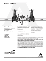
1
2
3
4
5
6
7
8
3
/8 – 16 var.
9
All Thread Red
1. Shaft
2. Spring retaining plate
3. Spring
4.
3
/8" threaded hole
(maintenance)
5. Spider
6. Spider retaining bolt
7. Seat ring
8. Clapper to shaft bolt
9. Seat ring retainer
WARNING
!
Depressurize valve before servicing.
The relief valve may be serviced while on or off the backflow pre-
venter valve.
NOTICE
Do not use a pipe wrench to remove the relief valve assembly from
the backflow preventer.
Relief Valve Disassembly
1. Disconnect the relief valve hose from the elbow in the bottom
flange cover at the swivel hose connection. Do not remove the
elbow.
2. If the valve is to be removed from the backflow preventer for
service, place a screw driver blade or flat bar across the edges
of the 2 hex head screws in the bottom flange cover and turn
counterclockwise to loosen the relief valve assembly.
3. Remove the 4 bottom bolts from the bottom of the relief valve
assembly with a
5
/16" socket or open-end wrench. Remove the
bottom flange cover.
4. Remove the piston assembly & sleeve from the relief valve body
by placing your index fingers through the slots in the side of the
body and pressing down on the top of the disc retainer in the
top of the piston assembly. (See Figure 7.)
5. Pull the piston assembly free of the body by grasping the sleeve
and pulling down.
6. Grip the sleeve and the piston assembly by the head of the hex
head bolt. Pull up on the sleeve to extend the diaphragm. Slide
the sleeve (Part #7013340) completely off of the diaphragm and
inspect the diaphragm for tears, holes or excessive wrinkles. If
the diaphragm is damaged, order a new piston/diaphragm as-
sembly.