Vega POINTRAC 31 Supplementary instructions
- Type
- Supplementary instructions
This manual is also suitable for
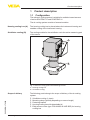
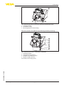
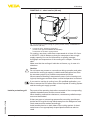
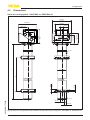
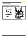
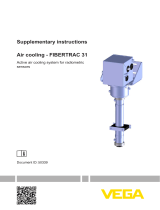
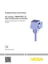
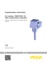
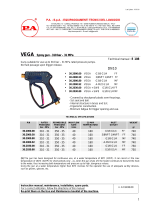
Vega POINTRAC 31 is a radiation-based point level switch designed for reliable detection of liquids, solids, and slurries. With its active air cooling system, it can operate in ambient temperatures up to 80°C (176°F) and is suitable for various applications in the process industry. The device features a compact design, easy installation, and a variety of process connections and materials to meet different requirements.
Vega POINTRAC 31 is a radiation-based point level switch designed for reliable detection of liquids, solids, and slurries. With its active air cooling system, it can operate in ambient temperatures up to 80°C (176°F) and is suitable for various applications in the process industry. The device features a compact design, easy installation, and a variety of process connections and materials to meet different requirements.


-
 1
1
-
 2
2
-
 3
3
-
 4
4
-
 5
5
-
 6
6
-
 7
7
-
 8
8
-
 9
9
-
 10
10
-
 11
11
-
 12
12
-
 13
13
-
 14
14
-
 15
15
-
 16
16
-
 17
17
-
 18
18
-
 19
19
-
 20
20
-
 21
21
-
 22
22
-
 23
23
-
 24
24


Vega POINTRAC 31 Supplementary instructions
- Type
- Supplementary instructions
- This manual is also suitable for
Vega POINTRAC 31 is a radiation-based point level switch designed for reliable detection of liquids, solids, and slurries. With its active air cooling system, it can operate in ambient temperatures up to 80°C (176°F) and is suitable for various applications in the process industry. The device features a compact design, easy installation, and a variety of process connections and materials to meet different requirements.
Ask a question and I''ll find the answer in the document
Finding information in a document is now easier with AI
Related papers
-
Vega SOLITRAC 31 Supplementary instructions
-
-
 Vega FIBERTRAC 31 Supplementary instructions
-
Vega Water/Air cooling MINITRAC 31 Supplementary instructions
-
 Vega FIBERTRAC 31 Supplementary instructions
-
 Vega FIBERTRAC 31 Supplementary instructions
-
 Vega FIBERTRAC 31 Supplementary instructions
-
 Vega FIBERTRAC 32 Supplementary instructions
-
 Vega FIBERTRAC 32 Supplementary instructions
-


Other documents
-
HQ W9-RSBN-34BN Datasheet
-
Delta Electronics POINTRACER User manual
-
LevelOne HVE-9002 User manual
-
LevelOne HVE-9000 User manual
-
LevelOne HVE-6000 User manual
-
-
LevelOne 590708 Datasheet
-
 9.solutions Savior Clamp User manual
-
 PA 30.2000.80 VEGA Technical Manual
-
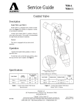 Alemite 7836-A User manual


