Page is loading ...

Supplementary instructions
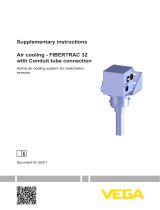
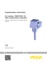
Air cooling - FIBERTRAC 31
Active air cooling system for radiometric
sensors
Document ID: 50339

2
Contents
Air cooling - FIBERTRAC 31 • Active air cooling system for radiometric sensors
50339-EN-201120
Contents
1 Product description ................................................................................................................. 3
1.1 Conguration .................................................................................................................... 3
2 Mounting ................................................................................................................................... 5
3 Replacement parts ................................................................................................................. 18
3.1 Available spare parts - air cooling ................................................................................... 18
4 Supplement ............................................................................................................................ 19
4.1 Technical data ................................................................................................................ 19
4.2 Dimensions .................................................................................................................... 21
Editing status: 2020-10-15

3
1 Product description
Air cooling - FIBERTRAC 31 • Active air cooling system for radiometric sensors
50339-EN-201120
1 Product description
1.1 Conguration
The active air cooling system is suitable for radiometric sensors of
series FIBERTRAC 31.
The air cooling system consists of several modules.
The housing cooling box is placed above the instrument housing and
enables cooling of the instrument housing.
The cooling module for the housing is also cooled by the housing
cooling box (A).
Theexiblecoolingmoduleforthescintillatorcoolstheactivemeas-
uring part of the sensor.
B
A
C
Fig. 1: Active air cooling system with fastening bracket
A Housing cooling box
B Housing cooling
C Scintillatorcooling(exible)
The following parts belong to the scope of delivery of the air cooling
system:
Housing cooling box (A)
Housing cooling (B)
Scintillator cooling (C)
Scope of delivery

4
1 Product description
Air cooling - FIBERTRAC 31 • Active air cooling system for radiometric sensors
50339-EN-201120
•
Scintillator cooling hose (1 piece)
•
Flange, sectioned (2 pieces)
•
Hexagon socket screw M5 x 12 (6 pieces)
•
Hexagon socket screw M5 x 14 (6 pieces)
•
Spring ring for M5 (6 pieces)
•
Sealing ring ø 42 x 6 mm (2 pieces)
•
Compression nut, top (1 piece)
•
Compression nut, bottom (1 piece)
•
Mounting clamp (quantity depending on sensor length)
•
Fastening bracket
•
Housing cooling box with detachable lid
•
Isolating sleeve (6 pieces)
•
Fixing screw M8 x 35 (2 pieces)
•
Fixing screw M8 x 40 (4 pieces)
•
Washer for M8 (10 pieces)
•
Spring ring for M8 (2 pieces)
•
Hexagon nut M8, self-locking (4 pieces)
•
Eddy current cooler (type FOS 208SS 25 HVE BSP) for housing
cooling box
•
Vortex cooler (type FOS 208SS 35 HVE BSP) for scintillator cool-
ing
•
Blind plug ¼" (3 pcs.)
•
NPT threaded adapter for vortex cooler (optional)
•
Hook wrench size 68 - 75, DIN 1810, Form B
Information:
When the sensor is ordered with cooling, the sensor and the air cool-
ing system are shipped pre-assembled.
If the air cooling system is ordered later, you have to mount it on the
sensor yourself.
Youcanndfurtherinformationinchapter"Mounting".

5
2 Mounting
Air cooling - FIBERTRAC 31 • Active air cooling system for radiometric sensors
50339-EN-201120
2 Mounting
Mounting preparations
Take note of the operating instructions manuals of the corresponding
radiometric sensors and the source holder.
Warning:
During all mounting and dismounting work, the source container must
be in switch position "OFF" and secured by a lock.
Carry out all work within the shortest possible time and at the largest
possible distance. Provide suitable shielding.
Avoid risk to other persons by taking suitable measures (e.g. safety
fence, etc.).
Mountingmayonlybecarriedoutbyauthorized,qualiedpersonnel
who are monitored for radiation exposure according to local laws or
thehandlingpermit.Takenoteofthespecicationsinthehandling
permit. Also take the local conditions into account.
Caution:
The cooling system is used in areas with high temperatures. There-
fore, use temperature-resistant cable and install it in such a way that
contact with hot components is avoided.
Information:
When the sensor is ordered with cooling, the sensor and the air cool-
ing system are shipped pre-assembled.
If the air cooling system is ordered later, you have to mount it on the
sensor yourself.
Required tools:
•
Hook wrench size 68 - 75, DIN 1810, Form B - for screwing on the
scintillator cooling hose (comes with the air cooling system)
•
Allenkeysize4-forthebisectionalholdingange
•
Fork wrench SW10 mm - for the mounting clip
•
Fork wrench SW13 mm (2 pieces) - for the housing cooling
•
Fork wrench SW19 mm (2 pcs.) - for vortex coolers
•
Acid-free grease - to screw in the compression nuts more easily
Take note of the following general mounting instructions:
•
First of all, mount the fastening bracket and the housing cooling,
and then the sensor.
•
The small lid of the instrument housing must point to the front after
mounting the fastening bracket (x)
•
The sensor together with the air cooling system is very heavy. Use
a suitable lifting device for mounting, e.g. a hoisting sling
•
To avoid penetration of moisture and dirt, you should remove the
protective caps of the connection openings just before connection
Mounting
1. Place the isolating sleeves (4) between the housing cooling (5)
and the fastening bracket (1).
Operating instructions
General mounting
instructions
Mount the fastening
bracket

6
2 Mounting
Air cooling - FIBERTRAC 31 • Active air cooling system for radiometric sensors
50339-EN-201120
1
2
3
4
5
6
Fig. 2: Housing cooling with mounted sensor
1 Fastening bracket
2 HexagonscrewM8(4pieces)
3 WasherforM8(4pieces)
4 Isolatingsleeve(4pieces)
5 Housing cooling
6 HexagonnutM8,self-locking(2pcs.)
2. Place the fastening bracket (1) onto the housing cooling (5). Make
sure that the cooling air connections point in a suitable direction.
Rotatingthefasteningbracketlater(1)isverydicult.
3. Connect the fastening bracket (1) with the housing cooling (5)
according to the illustration and tighten the screws (2, 6) with a
torque of 15 Nm (11.06 lbf ft). Provide counterforce with a second
fork wrench.
1. Insert the sensor into the housing cooling.
The small lid of the instrument housing must point to the front
after mounting on the fastening bracket (x).
5
1
x
Fig. 3: Mounting direction of the sensor towards the fastening bracket
1 Fastening bracket
5 Housing cooling
x Mounting direction of the housing
Inserting the sensor

7
2 Mounting
Air cooling - FIBERTRAC 31 • Active air cooling system for radiometric sensors
50339-EN-201120
2. It is advisable to place the sensor and the housing cooling on the
oorwhileinserting.Protectthesensorbycoveringthesensor
housing during mounting.
Mount the sensor with the two screws (7) in the appropriate posi-
tion.
1
7
8
9
4
Fig. 4: Mounting the sensor
1 Fastening bracket
4 Isolatingsleeve(2pieces)
7 HexagonscrewM8(2pieces)
8 RetainingwasherforM8(2pieces)
9 WasherforM8(4pieces)
Take note of the following general mounting instructions:
•
First of all, mount the fastening bracket and the housing cooling,
and then the sensor
•
The small lid of the instrument housing must point to the front after
mounting the fastening bracket (x)
•
The sensor together with the air cooling system is very heavy. Use
a suitable lifting device for mounting
Mount the scintillator cooling according to the following assembly
drawing:
Housing cooling
Mounting the scintillator
cooling

8
2 Mounting
Air cooling - FIBERTRAC 31 • Active air cooling system for radiometric sensors
50339-EN-201120
10
11
12
13
14
15
Fig. 5: Mounting scintillator cooling - upper part
10 Housing cooling
11 Holdingange(bisectional)
12 Hexagonscrew(6pieces)
13 Compression nut - top
14 Seal ring
15 Scintillatorcoolinghose(withconnectionthread)
1. Slide the upper compression nut (13) from below onto the black
scintillator of the sensor. Make sure that the upper compression
nut (13) has a fastening slot and that this slot points in the direc-
tion of the housing cooling (10).
2. Slide the seal ring (14) from below onto the scintillator cooling
hose of the sensor. The seal ring (14) encircles the scintillator
cooling hose very tightly and must be moved with a rolling motion
over the entire length of the scintillator cooling hose. Make sure
that the seal ring is not damaged or contaminated.
3. Push the upper compression nut (13) from below against the
housing cooling (10).
4. Placethetwohalfshellsoftheholdingange(11)fromtheside
onto the upper compression nut (13) and fasten to the housing
cooling (10) with the enclosed hexagon socket screws (12).
The compression nut remains rotatable.
5. Grease the upper thread of the scintillator cooling hose (15) with
acid-free grease, e.g. Fuchs Lubritech Gleitmo 155 (heat-resistant
hot thread compound). This makes screwing the parts together
easier.
6. Push the scintillator cooling hose (15) from below onto the scintil-
lator of the sensor.

9
2 Mounting
Air cooling - FIBERTRAC 31 • Active air cooling system for radiometric sensors
50339-EN-201120
7. Slide the upper seal ring (14) from below into the opening of the
upper compression nut (13). Make sure that the seal ring (14) is
clean and undamaged and not twisted during the process.
8. Slide the thread of the scintillator cooling hose (15) from below
into the upper compression nut (13). Screw the scintillator cooling
hose (15) slowly into the upper compression nut (13) up to the
stop.
Turn the compression nut (13) with the attached hook wrench. the
scintillator cooling hose is contracted on its thread in direction of
the housing cooling. Turn the upper compression nut (13) with the
enclosed hook wrench up to the stop.
9. The upper part of the scintillator cooling is then sealed. Mount the
lower part as follows:
15
14
16
17
Fig. 6: Mounting scintillator cooling - lower part
14 Seal ring
15 Scintillatorcoolinghose(withconnectionthread)
16 Sensor(scintillatorhose)
17 Compression nut - bottom
Tip:
The length of the scintillator cooling hose is measured exactly. Never-
theless you may have the impression that the scintillator cooling hose
is too long.
Align the scintillator cooling hose in a straight line and make sure that
the cooling hose is not bent. If necessary, the cooling hose can be
pressed slightly in the length.
Make sure that the black scintillator of the sensor protrudes slightly
out of the scintillator cooling hose.
10. Grease the lower thread of the scintillator cooling hose (15) with
acid-free grease. This makes screwing the parts together easier.
11. Slide a seal ring (14) from below onto the scintillator hose (16) of
the sensor. Make sure that the seal ring (14) is not damaged or
contaminated.
12. Slide the lower compression nut (17) from below onto the thread
of the scintillator cooling hose (15).
13. Screw the lower compression nut (17) slowly onto the scintillator
coolinghose(15)uptothestop.Applycounterforceonthexed
tube part of the scintillator cooling hose (15) with a strap wrench
(oillterwrench)andtightenthelowercompressionnut(17)with
the enclosed hook wrench up to the stop.
The scintillator cooling is now completely sealed.

10
2 Mounting
Air cooling - FIBERTRAC 31 • Active air cooling system for radiometric sensors
50339-EN-201120
Information:
The sensor together with the air cooling system is very heavy. Use a
suitable lifting device for mounting.
Useahoistingslingwithsucientloadingcapacity.Takenoteofthe
slingmarking.Youcanndtherespectiveweightoftheaircooling
system in chapter " Technical data".
Place the lifting sling around the cooling tube directly below the
ange.Theloopisaso-calledlark'sfoot.
Fasten the hoisting sling according to the following illustration.
Fig. 7: Attaching the sling
As soon as the air cooling system is mounted, you can install the sen-
sor with the air cooling system in your facility.
Lifting the air cool-
ing system
Mounting the sensor

11
2 Mounting
Air cooling - FIBERTRAC 31 • Active air cooling system for radiometric sensors
50339-EN-201120
You can mount the sensor on your vessel with the enclosed mount-
ing clamps. A number of mounting clamps come with the air cooling
system depending on the length of the sensor.
Use a mounting clamp approx. every 450 mm (17.72 in). Adjust the
distances between the attached mounting clips.
Take note of the minimum bending radius of the housing cooling,
which is 294 mm (11.57 in).
1. Determine the exact mounting position of one or several mounting
clamps and mark the holes.
Youcanndthedrillingtemplateinthetechnicaldata.
Align the mounting positions exactly and average the distances
between the enclosed mounting clamps.
Drill appropriate holes (max. M12) for fastening the mounting
clamps.
Note:
The mounting clamps do not come with fastening screws. Use fasten-
ing elements that are appropriate for the situation in your plant.
2. Positionthebaseplate(35)andfastenitinthespeciedmount-
ing position.
3. Fasten additional mounting clamps exactly aligned in the same
way.
28
30
31
32
34
35
Fig. 8: Mounting clamps
28 Hexagon screw M6 x 100
30 Cover plate - metal
31 Upper clamping jaw
32 Fasteningscrews(providedbythecustomer)
34 Lower clamping jaw
35 Bottom plate - Metal
4. Place the lower clamping jaw (34) onto the bottom plate (35).

12
2 Mounting
Air cooling - FIBERTRAC 31 • Active air cooling system for radiometric sensors
50339-EN-201120
5. Insert the sensor with the cooling system into the lower clamping
jaw (34) and align the cooling system.
6. Place the cover plate (30) onto the upper clamping jaw (31) and
place the two parts onto the lower clamping jaw (34).
7. Insert the two hexagon screws (28) into the holes of the cover
plate (30) and the upper clamping jaw (31) and then push the
hexagon screws (28) through the two clamping jaws.
8. Tighten the two hexagon screws (28) with a torque of 8 Nm
(5.9 lbf ft).
Youcanndfurtherinformationonsensormountingintheoperating
instructions manual of the sensor.
1. Open the fasteners (36) and remove the lid (37) from the lower
part of the housing cooling box (38).
2. To make mounting easier, screw the cable glands of the sensor
out of the instrument housing.
3. Place the lower part of the housing cooling box (38) on the fasten-
ing bracket (1).
4. Insert the 6 hexagon socket screws (39) from below through the
mounting bracket (1) and tighten the screws with a torque of
4.5 Nm (3.3 lbf ft).
40
39
38
41
41
36
37
Fig. 9: Mounting the housing cooling box
36 Fasteners with safety latch
37 Lid of the housing cooling box
38 Lower part of the housing cooling box
39 SpringringforM5(6pieces)
40 HexagonsocketscrewM5x14(6pieces)
41 Connectionopeningforvortexcooler(typeFOS208SS25HVEBSP)
Mounting the housing
cooling box

13
2 Mounting
Air cooling - FIBERTRAC 31 • Active air cooling system for radiometric sensors
50339-EN-201120
1. Open the fasteners (36) and remove the lid from the housing
cooling box (37).
2. Determine which cable gland you need for connection of the sen-
sor.
3. Pierce a small hole with a sharp tool (e.g. pricking awl, scriber,
etc.) in the center through the respective rubber diaphragms (42).
Do not use a knife or similar for puncturing
If you have accidentally pierced the wrong diaphragm, you can
simply exchange the rubber diaphragms. If you have pierced a
diaphragm too much, you can seal it with self-adhesive fabric
tape.
42
38
36
37
Fig. 10: Preparations for electrical connection
36 Fasteners with safety latch
37 Lid of the housing cooling box
38 Lower part of the housing cooling box
42 Rubber diaphragm
4. Insert the cable gland into the resulting opening and screw it
tightly to the sensor housing.
Make sure that the rubber diaphragm encircles the cable gland
completely so that not too much cooling air can escape.
5. Connect the sensor to voltage supply. Keep in mind the informa-
tion in the operating instructions of the corresponding sensor or in
the wiring diagram on the housing lid.
Note:
The cooling system is used in areas with high temperatures. There-
fore, use temperature-resistant cable and install it in such a way that
contact with hot components is avoided.
6. From the front side, place the lid of the housing cooling box (37)
onto the lower part of the housing cooling box (38).
Electrical connection

14
2 Mounting
Air cooling - FIBERTRAC 31 • Active air cooling system for radiometric sensors
50339-EN-201120
7. Close the two lateral fasteners (36).
Make sure that the fasteners (36) are provided with safety latches
against unintentional opening. To open a fastener, you have to
press the safety latch.
The scintillator cooling and the housing cooling box must be con-
nected to the cooling system.
All threads for the cooling connection on the sensor are inner threads.
Cooling systems (vortex cooler)
So-called Vortex coolers are proven possibilities for cooling the sen-
sor.
You can connect the cooling air output of the vortex cooler directly to
the housing cooling box or scintillator cooling.
The two vortex coolers are part of the scope of delivery. The coolers
thustperfectlytoyouraircoolingsystemwithrespecttosize,cool-
ing capacity and throughput.
X
Z
Y
Fig.11:Eddycurrentcooler(Vortexcooler)
x Hot exhaust air
y Supply air
z Cooling air
Caution:
The vortex cooler gets very hot during operation. Hot air at approx.
100 °C (212 °F) escapes from the exhaust opening. Furthermore, the
cooler or sensor can be very cold on the cold air side. Wear suitable
protective clothing and prevent people from touching the cooling
system by installing barriers, etc.
Make sure that the exhaust airstream can escape safely into the
open. Make sure that no heat-sensitive components or cables are in
the exhaust airstream.
Connect cooling

15
2 Mounting
Air cooling - FIBERTRAC 31 • Active air cooling system for radiometric sensors
50339-EN-201120
If you want to direct the exhaust airstream in another direction, you
havetousestandard,angledmetalttingswith¼"screwconnection.
1. The housing cooling box has two connection openings with ¼"
connection.
Close the free openings with a respective bling plug.
2. The two lateral opening on the housing cooling have no func-
tion. Close the openings with the attached blind plugs to avoid
penetration of dirt and moisture.
3. Connect the vortex coolers.
All threads for the cooling connection on the sensor are inner
threads.
The vortex cooler type FOS 208SS 25 HVE BSP powers the
housing cooling box. The vortex cooler type FOS 208SS 35 HVE
BSP is connected to the scintillator cooling.
Screw in the short cooling air output of the vortex cooler and
tighten it with a torque of 25 Nm (18.43 lbf ft).

16
2 Mounting
Air cooling - FIBERTRAC 31 • Active air cooling system for radiometric sensors
50339-EN-201120
b
a
d
c
c
Fig.12:Connectionofthecoolingairsystems(vortexcoolers)
a Cooling air inlet - scintillator cooling
(vortexcoolertypeFOS208SS35HVEBSP)
b Cooling air outlet - scintillator cooling
c Cooling air inlet - Housing cooling box
(vortexcoolertypeFOS208SS25HVEBSP)
Connection on the left or right possible
For cooling, use clean, water-free compressed air of class 3:3:2 acc.
to ISO 8573-1:2010. Make sure that your compressor has enough
supplycapacity.Youcanndinformationonquality,pressure,
throughput and temperature of the cooling air in chapter " Technical
data".
Make sure that the cooling air inlets do not freeze, e.g. in case of a
shutdown.
Caution:
Do not loosen any screws or connections during operation and make
sure that the cooling air supply is reliable and interruption-free. Plan
the necessary steps for a possible compressed air failure.
We recommend installing a temperature sensor (in the housing cool-
ing box) that triggers an alarm when a critical temperature is reached.
IfyouwanttousetheaircoolinginanSIL-qualiedapplication,you
have to assess the SIL failure rates of the complete air cooling system
and the cooling air supply yourself.

17
2 Mounting
Air cooling - FIBERTRAC 31 • Active air cooling system for radiometric sensors
50339-EN-201120
Take note of the operating instructions manuals of the corresponding
radiometric sensors and the source holder.
When handling radioactive substances, unnecessary radiation expo-
sure must be avoided.
If there are gaps or intervening spaces after mounting, provide pro-
tective fences or grids to keep hands away from the dangerous area.
Such areas must be marked accordingly.
Install a safety barrier on both sides of the cooling system. A sheet
metal cover or an appropriately shaped plastic sheet can also be
used.
Install a protective grid

18
3 Replacement parts
Air cooling - FIBERTRAC 31 • Active air cooling system for radiometric sensors
50339-EN-201120
3 Replacement parts
3.1 Available spare parts - air cooling
Selected components of the cooling are available as replacement
parts. The following parts are available:
The stated quantity is the quantity delivered.
2
1
3456
57
Fig. 13: Spare parts - air cooling with vortex cooler
1 Rubberdiaphragm(2pcs.)
2 Lid of the housing cooling box
3 Threadedadapter¼NPT(1pce.)
4 Distancethreadedadapterforvortexcooler¼NPT(1pce.)
5 Threadedadapterforvortexcooler¼NPT(1pce.)
6 Vortex cooler type FOS 208SS 35 HVE BSP (input for cooling air - scintilla-
torcooling)
7 Vortex cooler type FOS 208SS 25 HVE BSP (input for cooling air - housing
coolingbox)
Air cooling - vortex cool-
ers

19
4 Supplement
Air cooling - FIBERTRAC 31 • Active air cooling system for radiometric sensors
50339-EN-201120
4 Supplement
4.1 Technical data
General data
Take note of the information in the operating instructions manual of the installed FIBERTRAC 31
level sensor and the source holder
Material 316L corresponds to 1.4404 or 1.4435
Materials
Ʋ Housing cooling 316L
Ʋ Housing cooling box 316L
Ʋ Metal fabric hose of the scintillator
cooling
Stainless steel
Ʋ Seal NBR
Application temperature See in the following " Throughput - Coolant air"
Weight
Ʋ Housing cooling 2.3 kg (5.1 lbs)
Ʋ Scintillator cooling 8.8 kg/m (1.62 oz/in)
Ʋ Housing cooling box 3.2 kg (7.1 lbs)
Ʋ Fastening bracket 4.8 kg (10.6 lbs)
Ʋ Fastening clamp 0.48 kg (1.06 lbs)
Total length of the air cooling system max. 7 m (275.6 in)
Torques
Ʋ Screws, Sensor mounting (M8) 15 Nm (11.06 lbf ft)
Ʋ Nuts, housing cooling (M8) 15 Nm (11.06 lbf ft)
Ʋ Hexagon socket screws, holding
ange(M6)
4.5 Nm (3.3 lbf ft)
Ʋ Threadedttings,vortexcoolers 25 Nm (18.43 lbf ft)
Ʋ Screws for mounting clamps 8 Nm (5.9 lbf ft)
Connection thread of the cooling air
inputs
¼" DIN ISO 228 outer thread
(adaptersforNPTttingsareenclosedwithrespective
version)
Throughput - Coolant air
Quality of the compressed air ISO 8573-1:2010 [3:3:2]
Supply capacity - Compressor
1)
Ʋ Type FOS 208SS 25 HVE BSP 708 L/min (25 SCFM)
Ʋ Type FOS 208SS 35 HVE BSP 991 L/min (35 SCFM)
Air pressure of the supply air 5 … 7.9 bar (72 … 114 psig)
Temperature of the supply air < +20 … 25 °C (+68 … 77 °F)
Ambient temperature
Ʋ Sensor length 0.3 … 5 m (1 … 16.4 ft) +80 °C (+176 °F)
1)
at 6.9 bar (100 psig)

20
4 Supplement
Air cooling - FIBERTRAC 31 • Active air cooling system for radiometric sensors
50339-EN-201120
Ʋ Sensor length 5 … 7 m (16.4 … 23 ft) +70 °C (+158 °F)
Approvals
If you use an air cooling system in hazardous areas,
make sure that the max. permissible temperatures in the
Ex safety instructions are maintained around the sensor.
If this is ensured, the sensor can also be used with an air
cooling system in hazardous areas.
/