Page is loading ...

1
Product Data
PY3G
13 SEER SINGLE PACKAGED AIR CONDITIONER AND
GAS FURNACE SYSTEM WITH R--410A REFRIGERANT
SINGLE AND THREE PHASE
2--5 NOMINAL TONS (SIZES 024--060)
A09581
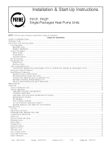
Fig. 1 -- Unit PY3G
Single--Packaged Products with Energy --Saving Features and
R--410A refrigerant.
S Up to 13.5 SEER
S Up to 81% AFUE
S Factory--Installed TXV
S Multi--Speed Blower--Standard
S Direct Spark Ignition
S Low Sound Levels
FEATURES/BENEFITS
One--piece heating and cooling units with low sound levels, easy
installation, low maintenance, and dependable performance.
Easy Installation
Factory--assembled package is a compact, fully self--contained,
combination gas heating/electric cooling unit that is prewired,
pre--piped, and pre--charged for minimum installation expense.
These units are available in a variety of standard and optional
heating/ cooling size combinations with voltage options to meet
residential and light commercial requirements. Units are
lightweight and install easily on a rooftop or at ground level. The
high tech composite base eliminates rust problems associated with
ground level applications.
Convertible duct configuration
Unit is designed for easy use in either downflow or horizontal
applications. Each unit is easily converted from horizontal to
downflow with the two standard duct covers. Downflow operation
is easily provided in the field to allow vertical ductwork
connections. The basepan utilizes knockout style seals on the
bottom openings to ensure a positive seal in the horizontal airflow
mode.
Efficient operation High--efficiency design offers SEER
(Seasonal Energy Efficiency Ratios) of up to 13.5 and AFUE
(Annual Fuel Utilization Ef ficiency) ratings as high as 80.4%.
Energy-- saving, direct spark ignition saves gas by operating only
when the room thermostat calls for heating. Standard units are
furnished with natural gas controls. A low--cost field installed kit
for propane conversion is available for all units.
PY3G have dedicated Low NOx units designed for California
installations. These models meet the California maximum oxides of
nitrogen (NOx) emissions requirement of 40 nanograms/joule or
less as shipped from the factory and MUST be installed in
California Air Quality Management Districts where a Low NOx
rule exists. Low NOx option is available on single phase models
only.
Durable, dependable components Compressors are designed
for high ef ficiency . Each compressor is hermetically sealed against
contamination to help promote longer life and dependable
operation. Each compressor also has vibration isolation to provide
quieter operation. All compressors have internal high pressure and
overcurrent protection.
Monoport inshot burners produce precise air--to--gas mixture,
which provides for clean and efficient combustion. The large
monoport on the inshot (or injection type) burners seldom, if ever,
requires cleaning. All gas furnace components are accessible in one
compartment.
Turbo--tubulart heat exchangers are constructed of aluminized
steel for corrosion resistance and optimum heat transfer for
improved efficiency. The tubular design permits hot gases to make
multiple passes across the path of the supply air.
In addition, dimples located on the heat exchanger walls force the
hot gases to stay in close contact with the walls, improving heat
transfer .
Direct--drive high efficiency brushless DC multi--speed blower
motor is standard on all PY3G models.
Direct--drive PSC condenser--fan motors are designed to help
reduce energy consumption and provide for cooing operation
downto40_F(4.4_C) outdoor temperature. Motormasterr II low
ambient kit is available as a field--installed accessory.
Thermostatic Expansion Valve -- A hard shutoff, balance port
TXV maintains a constant superheat at the evaporator exit (cooling
cycle) resulting in higher overall system efficiency.
Refrigerant system is designed to provide dependability. Liquid
filter driers are used to promote clean, unrestricted operation. Each
unit leaves the factory with a full refrigerant charge. Refrigerant
service connections make checking operating pressures easier.

2
High and Low Pressure Switches provide added reliability for the
compressor.
Indoor and Outdoor coils are computer--designed for optimum
heat transfer and efficiency. The indoor coil is fabricated from
copper tube and aluminum fins and is located inside the unit for
protection against damage. The outdoor coil is internally mounted
on the top tier of the unit. Copper fin coils and pre--coated fin coils
are available from the factory by special order. These coils are
recommended in applications where aluminum fins are likely to be
damaged due to corrosion. They are ideal for seacoast applications.
Low sound ratings ensure a quiet indoor and outdoor
environment with sound ratings as low as 75dBA.
Easy to service cabinets provide easy single--panel accessibility to
serviceable components during maintenance and installation. The
basepan with integrated drain pan provides easy ground level
installation with or without a mounting pad. Convenient handholds
are provided to manipulate the unit on the jobsite. A nesting feature
ensures a positive basepan to roof curb seal when the unit is roof
mounted. A convenient 3/4--in. (19.05 mm) wide perimeter flange
makes frame mounting on a rooftop easy.
TABLE OF CONTENTS
Features/Benefits 1--- 2..............................
Model N umber Nomenclature 3.......................
ARI Capacities 4....................................
P h y s i c a l D a t a 5 --- 6..................................
Options and Accessories 7...........................
Base Unit Dimensions 9--- 10.........................
Accessory Dimensions 11............................
Selection Procedure 12..............................
Pe r f o r m a n c e D a t a 1 3 --- 2 5............................
Typical Piping and Wiring 26..........................
Applicatio n Data 27.................................
Electrical Data 28...................................
Typical Wiring Schematics 29--- 31.....................
Controls 32........................................
Guide Specifications 33---34..........................
Standard metal duct covers with insulation come with the unit
and cover the horizontal duct openings. These can be left in place if
the units are converted to downflow.
Integrated Gas Control (IGC) board provides safe and efficient
control of heating and simplifies trouble--shooting through its
built--in diagnostic function.
Cabinets are constructed of heavyduty, phosphated, zinc--coated
prepainted steel capable of withstanding 500 hours in salt spray.
Interior surfaces of the evaporator/heat exchanger compartment are
insulated with cleanable semi--rigid insulation board, which keeps
the conditioned air from being affected by the outdoor ambient
temperature and provides improved indoor air quality. (Conforms
to American Society of Heating, Refrigeration and Air
Conditioning Engineers 62.2.) The sloped drain pan minimizes
standing water in the drain. An external drain is provided.
PY3G

3
MODEL NUMBER NOMENCLAT URE
PY3G
--- ---
024
A
Typ e of U ni t
P Y 3 G --- S i n g l e P a c k a g e d
Gas Heating/Electric
Cooling Unit
Nominal Cooling Capacity
024 --- 2.0 Tons
030 --- 2.5 Tons
036 --- 3.0 Tons
042 --- 3.5 Tons
048 --- 4.0 Tons
060 --- 5.0 Tons
W
Heat Input Size (Btuh)
040 --- 40,000
060 --- 60,000
090 --- 90,000
115 --- 115,000
130 --- 130,000
Electrical Supply
N --- 208/ 230--- 1---60
P --- 208/230---3--- 60
E --- 4 6 0 --- 3 --- 6 0
040
A
Series
Options
TP --- Base unit with tin plated indoor coil hairpins
See Price Page for full list of factory options.
Only used if ordering an option
LEGEND
AL --- Aluminum
CU --- Copper
N
Low NOx Indicator
A --- S t a n d a r d
N --- L o w N O x
Variations
ama
PY3G

4
ARI* CAPACITIES
Cooling Capacities and Efficiencies
UNIT PY3G NOMINAL TONS STANDARD CFM
NET COOLING
CAPACITIES (Btuh)
EER** SEER†
024 2 800 23,000 11.0 13.2
030 2-- 1/2 1000 28,600 11.2 13.5
036 3 1200 34,400 11.0 13.0
042 3-- 1/2 1400 40,500 11.2 13.2
048 4 1600 46,500 11.2 13.2
060 5 1750 57,000 11.0 13.4
LEGEND
d B --- Sound Levels (decibels)
db—Dry Bulb
SEER—Seasonal Energy Efficiency Ratio
wb—Wet Bulb
COP---C oef f icient of Performance
* Air Conditioing & Refrigeration Institute.
**At “A” conditions ---80_F (26.7_C) indoor db/67_F (19.4_C) indoor wb &
95_F(35_C) outdoor db.
{ Rated in accordance with U.S. Government DOE Department of Energy)
test procedures and/or ARI Standards 210/240.
Notes:
1. Ratings are net values, reflecting the effects of circulating fan heat.
Ratings are based on:
Cooling Standard: 80°F (26.7_C) db, 67°Fwb ( 19.4_ C ) i n d o o r e n t e r i n g --- a ir
temperature and 95°Fdb(35_C) outdoor entering---air temperature.
2. Before purchasing this appliance, read important energy cost and effi-
ciency information available from your retailer.
Gas Heating Capacities and Efficiencies
UNIT PY3G HEATING INPUT (Btuh)
OUTPUT CAPACITY
(Btuh)
TEMPERATURE RISE
RANGE °F(°C)
AFUE (%)
024040
030040
40,000 32,000
30--60
(16.7--33.3)
80.0
024060
030060
036060
042060
60,000
48,000
48,000
48,000
47,000
25--55
(13.9--30.6)
80.0
80.0
80.0
78.5
036090
042090
048090
060090
90,000
72,000
73,000
73,000
73,000
35--65
(19.4--36.1)
79.3
80.4
80.4
80.4
048115
060115
115,000 93,000
30--60
(16.7--33.3)
80.3
048130
060130
130,000 103,000
35--65
(19.4--36.1)
78.9
LEGEND
AFUE—Annual Fuel Utilization Efficiency
NOTE: Before purchasing this appliance, read important energy cost and efficiency information available from your retailer.
A--Weighted Sound Power Level (dBA)
UNIT PY3G
STANDARD
RATING dBA
TYPICAL OCTAVE BAND SPECTRUM (dBA without tone adjustment)
125 250 500 1000 2000 4000 8000
024 76 66.0 66.0 70.5 71.5 67.5 62.5 58.5
030 75 66.0 63.5 68.0 68.5 67.5 61.5 55.0
036 75 64.0 63.5 68.0 70.5 64.5 61.0 61.0
042 77 67.0 67.0 69.5 70.5 68.0 65.5 61.0
048 78 71.5 66.5 73.0 71.5 68.0 64.0 57.0
060 78 74.5 66.5 70.0 70.0 66.5 64.0 57.0
* Tested in accordance with ARI Standard 270 (not listed in ARI).
PY3G

5
PHYSICAL DATA
UNIT SIZE 024040 024060 030040 030060 036060 036090 042060 042090
NOMINAL CAPACITY (ton) 2 2 2 --- 1 / 2 2 --- 1 / 2 3 3 3 --- 1 / 2 3 --- 1 / 2
SHIPPING WEIGHT** lb.
SHIPPING WEIGHT** (kg)
329
149
329
149
334
152
334
152
344
156
344
156
435
197
435
197
COMPRESSORS
Quantity
Scroll
1
REFRIGERANT (R ---410A)
Quantity lb.
Quantity (kg)
4.8
2.2
4.8
2.2
6.2
2.8
6.2
2.8
6.4
2.9
6.4
2.9
6.1
2.7
6.1
2.7
REFRIGERANT METERING DEVICE TXV
OUTDOOR COIL
Rows...Fins/in.
Face Area (sq ft)
1..21
10.2
1...21
10.2
1...21
11.9
1...21
11.9
1...21
15.4
1...21
15.4
1...21
13.6
1...21
13.6
OUTDOOR FAN
Nominal CFM
Diameter in.
Diameter (mm)
Motor Hp (Rpm)
2800
24
609.6
1/5 ( 810)
2800
24
609.6
1/5 ( 810)
3000
24
609.6
1/5 ( 810)
3000
24
609.6
1/5 ( 810)
3200
24
609.6
1/5 ( 810)
3200
24
609.6
1/5 ( 810)
3600
26
660.4
1/5 ( 810
3600
26
660.4
1/5 ( 810)
INDOOR COIL
Rows...Fins/in.
Face Area (sq ft)
2...17
3.7
2...17
3.7
3...17
3.7
3...17
3.7
3...17
3.7
3...17
3.7
3...17
4.7
3...17
4.7
INDOOR BLOWER
Nominal Cooling Airflow (Cfm)
Size in.
Size (mm.)
Motor HP (RPM)
800
800
1000
1000
1200
1200
1400
1400
800
10x10
254x254
1/2 ( 1050)
800
10x10
254x254
1/2 ( 1050)
1000
10x10
254x254
1/2 ( 1050)
1000
10x10
254x254
1/2 ( 1050)
1200
11x10
279.4x254
3/4 ( 1000)
1200
11x10
279.4x254
3/4 ( 1000)
1400
11x10
279.4x254
3/4 ( 1075)
1400
11x10
279.4x254
3/4 ( 1075)
FURNACE SECTION*
Burner Orifice No. (Qty...Drill Size)
Natural Gas (Factory Installed)
Propane Gas
2...44
2...55
2...38
2...53
2...44
2...55
2...38
2...53
2...38
2...53
3...38
3...53
2...38
2...53
3...38
3...53
HIGH--PRESSURE SWITCH
(psig) Cut--out Reset (Auto)
650 +/-- 15
420 +/-- 25
LOSS--OF--CHARGE / LOW --PRESSURE
SWITCH (Liquid Line) (psig) cut--out Reset
(auto)
20 +/-- 5
45 +/-- 10
RETURN ---AIR FILTERS†}
Throwaway Size in.
(mm)
20x20x1
508x508x25
20x24x1
508x610x25
24x30x1
610x762x25
*Based on altitude of 0 to 2000 ft ( 0 ---610 m).
{ Required filter sizes shown are based on the larger of the ARI (Air Conditioning and Refrigeration Institute) rated cooling airflow or the heating airflow velocity
of 300 ft/minute for throwaway type. Air filter pressure drop for non ---standard filters must not exceed 0.08 IN. W.C.
} If using accessory filter rack refer to the filter rack installation instructions for correct filter sizes and quantity.
** For 460 volt u nits, add 14 lbs (6.35 kg) to the shipping weight.
PY3G

6
PHYSICAL DATA (CONT)
UNIT SIZE 048090 048115 048130 060090 060115 060130
NOMINAL CAPACITY (ton) 4 4 4 5 5 5
SHIPPING WEIGHT** lb
SHIPPING WEIGHT** kg
443
201
443
201
443
201
465
211
465
211
465
211
COMPRESSORS
Quantity
Scroll
1
REFRIGERANT (R ---410A)
Quantity lb
Quantity (kg.)
6.4
2.9
6.4
2.9
6.4
2.9
10.0
4.5
10.0
4.5
10.0
4.5
REFRIGERANT METERING DEVICE TXV
OUTDOOR COIL
Rows...Fins/in.
Face Area (sq ft)
1...21
15.5
1...21
15.5
1...21
15.5
2...21
15.5
2...21
15.5
2...21
15.5
OUTDOOR FAN
Nominal Cfm
Diameter in.
Diameter (mm)
Motor Hp (Rpm)
4000
26
660.4
1/5 ( 810)
4000
26
660.4
1/5 ( 810)
4000
26
660.4
1/5 ( 810)
3200
26
660.4
1/5 ( 810)
3200
26
660.4
1/5 ( 810)
3200
26
660.4
1/5 ( 810)
INDOOR COIL
Rows...Fins/in.
Face Area (sq ft)
3...17
4.7
3...17
4.7
3...17
4.7
3...17
5.7
3...17
5.7
3...17
5.7
INDOOR BLOWER
Nominal Cooling Airflow (Cfm)
Size in.
Size (mm)
Motor HP (RPM)
1600 1600 1600 1750 1750
1750
1600
11x10
279.4x254
1.0 (1075)
1600
11x10
279.4x254
1.0 (1075)
1600
11x10
279.4x254
1.0 (1075)
1750
11x10
279.4x254
1.0 (1040)
1750
11x10
279.4x254
1.0 (1040)
1750
11x10
279.4x254
1.0 (1040)
FURNACE SECTION*
Burner Orifice No. (Qty...Drill Size)
Natural Gas (Factory Installed)
Propane Gas
3...38
3...53
3...33
3...51
3...31
3...49
3...38
3...53
3...33
3...51
3...31
3...49
HIGH--PRESSURE SWITCH
(psig) Cut--out Reset (Auto)
650 +/-- 15
420 +/-- 25
LOSS--OF--CHARGE / LOW --PRESSURE
SWITCH (Liquid Line) (psig) cut--out Reset
(auto)
20 +/-- 5
45 +/-- 10
RETURN--AIR FILTERS Throwaway†} in.
(mm)
24x36x1
610x914x25
*Based on altitude of 0 to 2000 ft ( 0 ---610 m).
{ Required filter sizes shown are based on the larger of the ARI (Air Conditioning and Refrigeration Institute) rated cooling airflow or the heating airflow velocity
of 300 ft/minute for throwaway type. Air filter pressure drop for non ---standard filters must not exceed 0.08 IN. W.C.
} If using accessory filter rack refer to the filter rack installation instructions for correct filter sizes and quantity.
** For 460 volt u nits, add 14 lbs (6.35 kg) to the shipping weight.
PY3G

7
OPTIONS AND ACCESSORIES
Field--installed accessories
Economizer with Solid--State Controls and Barometric
Relief Dampers
Manual Air Damper (25% open)
Filter Rack
Flat Roof Curbs (8--in. [203.2 mm] and 14--in. [355.6 mm])
Square--to--Round Duct Transition Kit
Thermostats
Crankcase Heater
Compressor Start Kit (for use on single--phase units only)
Natural--to--propane Gas Conversion Kit
High Altitude Propane Conversion Kit
Propane--to--natural Gas Conversion Kit
Rigging Kit
Low Ambient Kit (Motormaster® II Control)
Solid --State Time Guard® II Device
Economizer with solid--state controls and barometric relief
dampers includes filter racks and provide outdoor air during
cooling and reduce compressor operation.
Manual outside air damper includes hood and filter rack with
adjustable damper blade for up to 25% outdoor air.
Flat roof curbs in both 8 in. (203.2 mm) and 14 in. (355.6 mm)
sizes are available for roof mounted applications.
Square --to--round duct tra nsition kit enables 024--048 size units
to be fitted to 14 in. (355.6 mm) round ductwork.
Compr e ssor start kit assists compressor start--up by providing
additional starting torque on single phase units and prolongs
compressor motor life.
Corporate Thermostats provide control for the system heating
and cooling functions. Thermostat models are available in both
programmable and non-- programmable versions.
Crankcase heater provides anti-- floodback protection for
low--load cooling applications.
Natural--to--propane gas conversion kit allows for conversion
from natural gas to propane gas for standard altitude (0 to 2000 ft
[0 to 610 m] above sea level).
Rigging kit includes lifting brackets which are inserted into the
unit base rigging holds to lift unit for rooftop applications.
Low--ambient kit (Motormaster II control) allows the use of
mechanical cooling down to outdoor temperatures as low as 0_F
(--18_C) when properly installed.
Solid-- state Time Guard II device provides short--cycling
protection for the compressor. Not required with corporate
electronic thermostats.
Filter rack features easy installation, serviceability , and
high--filtering performance for vertical applications.
High altitude propane conversion kit is for use at 2001 to 6000
ft (610 to 1829 m) above sea level. Kit consists of propane gas
orifices that compensate for gas heat operation at high altitude.
Propane--to-- natural conversion kit is for use at standard
altitudes (0 to 2000 ft [0 to 610 m] above sea level). Kit contains
natural gas orifices and gas valve spring to convert the unit back to
natural gas.
PY3G

8
ECONOMIZER
COIL
FILTER
SIDE VIEW
CAULK BOTTOM CORNER
OF ECONOMIZER
ON EACH SIDE
BASE
COIL
FLANGE
ON BASE
DET
AIL
ECONOMIZER
FI LTER
FILTER ACCESS DOOR
(HORIZONTAL
APPLICATION ONLY.)
DO NOT REMOVE
FROM DOWNFLOW
DISCHARGE.
REPLACEMENT
PANEL
HOLE FOR
ECONOMIZER
WIRING HARDNESS
DOOR
LATCH ANGLE
HINGED FILTER
ACCESS DOOR
INSTALL
FILTER ACCESS
DOOR STICKER
ALUMINUM
FILTER
RAINHOOD
11 13/32”
17 13/32
16 1/4”
EV APORATOR
COIL
TOP FILTER RACK
BEND FLANGE AT 90˚-SCREW TO
DIVIDER WITH 1-IN. SCREW
BOTTOM FILTER
RACK
DAMPER
BLADE
MANUAL OUTSIDE
AIR HOOD
REPLACEMENT
PANEL
ECONOMIZER
FILTER RACK
MANUAL OUTSIDE AIR DAMPER
A05239
PY3G

9
UNIT DIMENSIONS -- PY3G024--036
A08598
PY3G

10
UNIT DIMENSIONS -- PY3G042--060
A08599
PY3G

11
ACCESSORY DIMENSIONS
Gask et around
outer edge
Insulated
deck pan
Gask et around
duct
S/A
R/A
HVAC unit
base
*Gask eting
outer flange
Flashing field
supplied
Roofing material
field supplied
Cant str ip
field supplied
*Provided with roof curb
Roof
Ductwork
field supplied
Insulation (field
supplied)
Roof curb*
Wood nailer*
Gask eting
inner flange*
Scre w
(NO TE A)
Roof Curb for Small Cabinet
Note A: When unit mounting scre w is used,
retainer bra cke t must also be used.
HVAC unit
base
*Gask eting
outer flange
Flashing field
supplied
Roofing material
field supplied
Cant str ip
field supplied
*Provided with roof curb
Roof
Ductwork
field supplied
Insulation (field
supplied)
Roof curb*
Wood nailer*
Gask eting
inner flange*
Scre w
(NOTE A)
Roof Curb for Large Cabinet
Note A: When unit mounting scre w is used,
retainer bra cket must also be used.
A
B Typ.
Supply opening
(B x C)
Long
Support
D
F
Return opening
(B X C)
Insulated
deck pan
Short
Support
C Typ.
G
E
F
G
D
E
A05308
UNIT SIZE
CATALOG
NUMBER
A
IN. (MM)
B
IN. (MM)
C
IN. (MM)
D
IN. (MM)
E
IN. (MM)
F
IN. (MM)
G
IN. (MM)
PY3G024--036
CPRFCURB006A00 8 (203) 11 (279) 16--1/2 (419) 28--3/4 (730) 30--3/8 (771) 44--5/16 (1126) 45--15/16 (1167)
CPRFCURB007A00 14 (356) 11 (279) 16--1/2 (419) 28--3/4 (730) 30--3/8 (771) 44--5/16 (1126) 45--15/16 (1167)
PY3G042--060
CPRFCURB008A00 8 (203) 16--3/16 (411) 17--3/8 (441) 40--1/4 (1022) 41--15/16 (1065) 44--7/16 (1129) 46--1/16 (1169)
CPRFCURB009A00 14 (356) 16--3/16 (411) 17--3/8 (441) 40--1/4 (1022) 41--15/16 (1065) 44--7/16 (1129) 46--1/16 (1169)
NOTES:
1. Roof curb must be set up for unit being installed.
2. Seal strip must be applied, as required, to unit being installed.
3. Roof curb is made of 16--gauge steel.
4. Attach ductwork to curb (flanges of duct rest on curb).
5. Insulated panels: 1--in. (25.4 mm) thick fiberglass 1 lb. density.
6. When unit mo unting screw is used (see No te A), a retainer brack et must be used as well. This b racket must also be used when required by code for hurricaneorseismic
conditions. This bracket is available through Micrometl.
PY3G

12
SELECTION PROCEDURE (WITH EXAMPLE)
1. Determine cooling and heating requirements at
design conditions:
Given:
Required Cooling Capacity (TC) 34,000 Btuh..........
Sensible Heat Capacity (SHC) 25,000 Btuh............
Required Heating Capacity 60,000 Btuh...............
Condenser Entering Air Temperature 95°F(35°C).......
Indoor--Air Temperature 80°F(26°C)edb 67°F(19°C) ewb
Evaporator Air Quantity 1200 CFM..................
External Static Pressure 0.300 IN. W.C.................
Electrical Characteristics 230--1--60...................
2. Select unit b ased on required cooling capacity.
Enter Net Cooling Capacities table at condenser entering
temperature of 95°F(35°C). Unit 036 at 1200 cfm and 67°F
(19°C) ewb (entering wet bulb) will provide a total capacity of
34,400 Btuh and a SHC of 25,900 Btuh. Calculate SHC correction,
if required, using Note 4 under Cooling Capacities tables.
3. Select heating capacity of unit to provide design
condition requirement.
In the Heating Capacities and Efficiencies table, note that the unit
036090 will provide 72,000 Btuh with an input of 90,000 Btuh.
4. Determine fan speed and power requirements at
design conditions.
Before entering the air delivery tables, calculate the total static
pressure required. From the given example, the Wet Coil Pressure
Drop T able, and the Filter Pressure Drop Table:
External Static Pressure 0.300 IN. W.C.
Filter 0.130 IN. W.C.
Wet Coil Pressure Drop 0.100 IN. W
.C
Total Static Pressure 0.530 IN. W.C
Enter the table for Dry Coil Air Delivery—Horizontal and
Downflow Discharge. At .530 IN. W.C. ESP, the closest speed to
1200 CFM is Med-- High (orange wire), which delivers 1316 CFM
at .6 in ESP.
5. Select unit that corresponds to power source
available.
The Electrical Data Table shows that the unit is designed to operate
at 230-- 1-- 60.
PY3G

13
PERFORMANCE DATA
PY3G024
EVAPORATOR AIR
CONDENSER ENTERING AIR TEMPERATURES _F(_C)
75 (23.9) 85 (29.4) 95 (35) 105 (40.6) 115 (46.1) 125 (51.7)
CFM/BF
EWB
_F
(_C)
Capacity MBtuh
Tot a l
Sys
kW
Capacity MBtuh
Tot a l
Sys
KW
Capacity MBtuh
Tot a l
Sys
KW
Capacity MBtuh
Tot a l
Sys
KW
Capacity MBtuh
Tot a l
Sys
KW
Capacity MBtuh
Tot a l
Sys
KW
Tot a l Sens Tot a l Sens Tot a l Sens Tot a l Sens Tot a l Sens Tot a l Sens
700/0.07
57
(13.8)
22.74 22.74 1.66 21.26 21.26 1.85 19.77 19.77 2.06 18.28 18.28 2.29 16.77 16.77 2.54 15.24 15.24 2.80
62
(16.6)
23.94 20.55 1.66 22.18 19.57 1.86 20.42 18.59 2.07 18.67 17.59 2.30 16.93 16.57 2.54 15.24 15.24 2.80
63*
(17.2)
24.48 17.00 1.67 22.68 16.12 1.86 20.88 15.23 2.07 19.08 14.35 2.30 17.27 13.46 2.54 15.45 12.56 2.81
67
(19.4)
26.34 17.55 1.67 24.42 16.65 1.86 22.49 15.76 2.07 20.57 14.86 2.30 18.64 13.97 2.55 16.70 13.07 2.82
72
(22.2)
28.95 14.51 1.67 26.85 13.70 1.87 24.76 12.88 2.08 22.66 12.07 2.31 20.56 11.25 2.56 18.45 10.43 2.83
800/0.09
57
(13.8)
23.78 23.78 1.68 22.21 22.21 1.87 20.64 20.64 2.08 19.06 19.06 2.31 17.46 17.46 2.56 15.85 15.85 2.82
62
(16.6)
24.57 22.03 1.68 22.75 20.99 1.87 20.94 19.93 2.08 19.15 18.83 2.31 17.46 17.46 2.56 15.85 15.85 2.82
63*
(17.2)
25.10 18.06 1.68 23.23 17.14 1.88 21.36 16.21 2.09 19.49 15.29 2.32 17.62 14.37 2.56 15.74 13.44 2.82
67
(19.4)
27.00 18.66 1.69 25.00 17.73 1.88 23.00 16.80 2.09 21.01 15.87 2.32 19.01 14.94 2.57 17.00 14.00 2.83
72
(22.2)
29.65 15.23 1.69 27.48 14.39 1.89 25.30 13.54 2.10 23.13 12.71 2.33 20.96 11.86 2.58 18.77 11.01 2.84
900/0.1
57
(13.8)
24.67 24.67 1.70 23.02 23.02 1.89 21.37 21.37 2.10 19.71 19.71 2.33 18.05 18.05 2.58 16.36 16.36 2.84
62
(16.6)
25.09 23.40 1.70 23.23 22.27 1.89 21.39 21.39 2.10 19.71 19.71 2.33 18.04 18.04 2.58 16.35 16.35 2.84
63*
(17.2)
25.60 19.06 1.70 23.66 18.11 1.89 21.74 17.15 2.10 19.81 16.20 2.33 17.89 15.24 2.58 15.96 14.27 2.84
67
(19.4)
27.52 19.73 1.70 25.45 18.76 1.90 23.40 17.80 2.11 21.34 16.83 2.34 19.29 15.87 2.59 17.23 14.89 2.85
72
(22.2)
30.21 15.91 1.71 27.97 15.04 1.90 25.72 14.18 2.11 23.50 13.31 2.35 21.26 12.45 2.60 19.02 11.58 2.86
See Legend and Notes o n Page 19.
PY3G

14
PERFORMANCE DATA
PY3G030
EVAPORATOR AIR
CONDENSER ENTERING AIR TEMPERATURES _F(_C)
75 (23.9) 85 (29.4) 95 (35) 105 (40.6) 115 (46.1) 125 (51.7)
CFM/BF
EWB
_F
(_C)
Capacity MBtuh
Tot a l
Sys
KW
Capacity MBtuh
Tot a l
Sys
KW
Capacity MBtuh
Tot a l
Sys
KW
Capacity MBtuh
Tot a l
Sys
KW
Capacity MBtuh
Tot a l
Sys
KW
Capacity MBtuh
Tot a l
Sys
KW
Tot a l Sens Tot a l Sens Tot a l Sens Tot a l Sens Tot a l Sens Tot a l Sens
875/0.03
57
(13.8)
29.20 29.20 2.09 27.20 27.20 2.30 25.19 25.19 2.52 23.18 23.18 2.77 21.16 21.16 3.04 19.13 19.13 3.32
62
(16.6)
30.09 26.44 2.09 27.78 25.28 2.30 25.48 24.10 2.52 23.22 23.12 2.77 21.16 21.16 3.04 19.12 19.12 3.32
63*
(17.2)
30.75 21.65 2.09 28.36 20.61 2.30 25.99 19.56 2.52 23.63 18.51 2.77 21.26 17.45 3.04 18.90 16.38 3.32
67
(19.4)
33.12 22.39 2.08 30.58 21.34 2.29 28.05 20.29 2.52 25.52 19.23 2.77 23.00 18.16 3.04 20.48 17.08 3.32
72
(22.2)
36.50 18.28 2.08 33.73 17.33 2.29 30.97 16.37 2.52 28.22 15.41 2.77 25.48 14.44 3.04 22.73 13.46 3.32
1000/0.03
57
(13.8)
30.51 30.51 2.12 28.39 28.39 2.33 26.27 26.27 2.56 24.14 24.14 2.80 22.01 22.01 3.07 19.87 19.87 3.35
62
(16.6)
30.85 28.45 2.12 28.49 28.24 2.33 26.26 26.26 2.56 24.14 24.14 2.80 22.01 22.01 3.07 19.86 19.86 3.35
63*
(17.2)
31.44 23.11 2.12 28.97 22.02 2.33 26.51 20.93 2.56 24.07 19.84 2.81 21.63 18.73 3.07 19.21 17.60 3.35
67
(19.4)
33.86 23.94 2.12 31.22 22.85 2.33 28.60 21.75 2.55 25.99 20.65 2.80 23.40 19.53 3.07 20.80 18.40 3.35
72
(22.2)
37.30 19.27 2.11 34.43 18.29 2.32 31.58 17.30 2.55 28.74 16.31 2.80 25.91 15.31 3.07 23.07 14.29 3.35
1125/0.04
57
(13.8)
31.61 31.61 2.15 29.39 29.39 2.36 27.17 27.17 2.59 24.95 24.95 2.84 22.72 22.72 3.10 20.48 20.48 3.39
62
(16.6)
31.61 31.61 2.15 29.39 29.39 2.36 27.17 27.17 2.59 24.95 24.95 2.84 22.72 22.72 3.10 20.48 20.48 3.39
63*
(17.2)
31.97 24.51 2.15 29.43 23.38 2.36 26.91 22.25 2.59 24.41 21.10 2.84 21.92 19.95 3.10 19.45 18.75 3.39
67
(19.4)
34.42 25.44 2.15 31.71 24.30 2.36 29.02 23.16 2.59 26.35 22.01 2.84 23.69 20.84 3.10 21.05 19.65 3.39
72
(22.2)
37.91 20.22 2.14 34.96 19.20 2.35 32.03 18.19 2.58 29.12 17.17 2.83 26.22 16.14 3.10 23.32 15.10 3.39
See Legend and Notes o n Page 19.
PY3G

15
PERFORMANCE DATA (CONT)
PY3G036
EVAPORATOR AIR
CONDENSER ENTERING AIR TEMPERATURES _F(_C)
75 (23.9) 85 (29.4) 95 (35) 105 (40.6) 115 (46.1) 125 (51.7)
CFM/BF
EWB
_F
(_C)
Capacity MBtuh
Tot a l
Sys
KW
Capacity MBtuh
Tot a l
Sys
KW
Capacity MBtuh
Tot a l
Sys
KW
Capacity MBtuh
Tot a l
Sys
KW
Capacity MBtuh
Tot a l
Sys
KW
Capacity MBtuh
Tot a l
Sys
KW
Tot a l Sens Tot a l Sens Tot a l Sens Tot a l Sens Tot a l Sens Tot a l Sens
1050/0.04
57
(13.8)
35.66 35.66 2.38 32.84 32.84 2.71 30.06 30.06 3.07 27.32 27.32 3.47 24.62 24.62 3.91 21.93 21.93 4.39
62
(16.6)
37.06 32.25 2.39 33.82 30.46 2.71 30.65 28.68 3.07 27.56 26.88 3.47 24.62 24.62 3.91 21.93 21.93 4.39
63*
(17.2)
37.87 26.52 2.39 34.55 24.93 2.71 31.28 23.37 3.08 28.09 21.82 3.48 24.95 20.29 3.91 21.88 18.77 4.39
67
(19.4)
40.79 27.41 2.39 37.23 25.80 2.72 33.74 24.21 3.08 30.32 22.64 3.48 26.96 21.09 3.92 23.65 19.54 4.39
72
(22.2)
44.91 22.49 2.39 41.02 21.04 2.72 37.19 19.62 3.09 33.45 18.21 3.49 29.78 16.82 3.93 26.16 15.44 4.40
1200/0.04
57
(13.8)
37.24 37.24 2.43 34.27 34.27 2.76 31.33 31.33 3.12 28.44 28.44 3.52 25.58 25.58 3.96 22.76 22.76 4.44
62
(16.6)
37.97 34.65 2.43 34.64 32.72 2.76 31.35 31.35 3.12 28.43 28.43 3.52 25.58 25.58 3.96 22.75 22.75 4.44
63*
(17.2)
38.73 28.25 2.43 35.29 26.59 2.76 31.91 24.95 3.12 28.60 23.33 3.52 25.37 21.73 3.96 22.21 20.12 4.44
67
(19.4)
41.71 29.24 2.44 38.02 27.56 2.76 34.40 25.90 3.13 30.86 24.26 3.53 27.40 22.63 3.97 24.00 21.00 4.44
72
(22.2)
45.90 23.65 2.44 41.86 22.16 2.77 37.91 20.68 3.13 34.05 19.23 3.54 30.26 17.79 3.98 26.53 16.36 4.45
1350/0.05
57
(13.8)
38.59 38.59 2.48 35.47 35.47 2.81 32.40 32.40 3.17 29.37 29.37 3.57 26.39 26.39 4.01 23.43 23.43 4.49
62
(16.6)
38.77 36.79 2.48 35.46 35.46 2.81 32.39 32.39 3.17 29.37 29.37 3.57 26.38 26.38 4.01 23.43 23.43 4.49
63*
(17.2)
39.40 29.91 2.48 35.85 28.18 2.81 32.38 26.47 3.17 28.99 24.78 3.57 25.69 23.09 4.01 22.46 21.40 4.49
67
(19.4)
42.41 31.01 2.48 38.61 29.26 2.81 34.89 27.52 3.18 31.27 25.81 3.58 27.72 24.10 4.02 24.26 22.39 4.49
72
(22.2)
46.65 24.77 2.49 42.51 23.22 2.82 38.45 21.70 3.18 34.49 20.20 3.58 30.61 18.72 4.03 26.80 17.24 4.50
See Legend and Notes o n Page 19.
PY3G

16
PERFORMANCE DATA
PY3G042
EVAPORATOR AIR
CONDENSER ENTERING AIR TEMPERATURES _F(_C)
75 (23.9) 85 (29.4) 95 (35) 105 (40.6) 115 (46.1) 125 (51.7)
CFM/BF
EWB
(_C)
Capacity MBtuh
Tot a l
Sys
KW
Capacity MBtuh
Tot a l
Sys
KW
Capacity MBtuh
Tot a l
Sys
KW
Capacity MBtuh
Tot a l
Sys
KW
Capacity MBtuh
Tot a l
Sys
KW
Capacity MBtuh
Tot a l
Sys
KW
Tot a l Sens Tot a l Sens Tot a l Sens Tot a l Sens Tot a l Sens Tot a l Sens
1225/0.03
57
(13.8)
40.45 40.45 3.00 37.98 37.98 3.37 35.49 35.49 3.78 32.98 32.98 4.20 30.44 30.44 4.65 27.84 27.84 5.10
62
(16.6)
42.06 37.63 2.94 39.15 35.73 3.33 36.25 33.83 3.74 33.37 31.92 4.18 30.48 30.39 4.64 27.88 27.88 5.10
63*
(17.2)
42.93 30.96 2.91 39.95 29.27 3.31 36.96 27.59 3.72 33.97 25.92 4.17 30.95 24.26 4.63 27.90 22.59 5.10
67
(19.4)
46.12 31.94 2.80 42.92 30.23 3.19 39.72 28.52 3.61 36.53 26.83 4.05 33.31 25.15 4.52 30.04 23.46 4.99
72
(22.2)
50.58 26.16 2.65 47.09 24.61 3.04 43.59 23.08 3.46 40.11 21.56 3.90 36.60 20.05 4.37 33.04 18.53 4.84
1400/0.04
57
(13.8)
42.24 42.24 2.98 39.61 39.61 3.35 36.97 36.97 3.76 34.32 34.32 4.18 31.63 31.63 4.63 28.88 28.88 5.08
62
(16.6)
43.11 40.44 2.95 40.11 38.38 3.34 37.15 36.28 3.75 34.31 34.31 4.18 31.62 31.62 4.63 28.88 28.88 5.08
63*
(17.2)
43.91 32.97 2.92 40.81 31.21 3.32 37.71 29.45 3.73 34.61 27.70 4.18 31.49 25.96 4.64 28.35 24.21 5.12
67
(19.4)
47.15 34.07 2.81 43.82 32.28 3.20 40.50 30.50 3.62 37.19 28.73 4.06 33.86 26.97 4.53 30.50 25.20 5.00
72
(22.2)
51.67 27.51 2.65 48.05 25.91 3.05 44.42 24.32 3.46 40.81 22.75 3.91 37.19 21.19 4.38 33.51 19.62 4.85
1575/0.05
57
(13.8)
43.75 43.75 2.97 40.99 40.99 3.34 38.22 38.22 3.75 35.43 35.43 4.17 32.62 32.62 4.62 29.74 29.74 5.07
62
(16.6)
44.02 42.95 2.96 41.01 41.01 3.34 38.21 38.21 3.75 35.43 35.43 4.17 32.61 32.61 4.62 29.74 29.74 5.07
63*
(17.2)
44.67 34.90 2.94 41.47 33.06 3.33 38.28 31.23 3.75 35.10 29.41 4.20 31.91 27.58 4.66 28.70 25.74 5.14
67
(19.4)
47.93 36.13 2.82 44.51 34.26 3.21 41.09 32.40 3.63 37.69 30.56 4.08 34.28 28.71 4.54 30.85 26.85 5.02
72
(22.2)
52.51 28.80 2.67 48.78 27.15 3.06 45.05 25.51 3.48 41.34 23.89 3.93 37.63 22.28 4.39 33.86 20.67 4.87
See Legend and Notes o n Page 19.
PY3G

17
PERFORMANCE DATA (CONT)
PY3G048
EVAPORATOR AIR
CONDENSER ENTERING AIR TEMPERATURES _F(_C)
75 (23.9) 85 (29.4) 95 (35) 105 (40.6) 115 (46.1) 125 (51.7)
CFMBF
EWB
_F
(_C)
Capacity MBtuh
Tot a l
Sys
KW
Capacity MBtuh
Tot a l
Sys
KW
Capacity MBtuh
Tot a l
Sys
KW
Capacity MBtuh
Tot a l
Sys
KW
Capacity MBtuh
Tot a l
Sys
KW
Capacity MBtuh Tota l
Sys
KW
Tot a l Sens Tot a l Sens Tot a l Sens Tot a l Sens Tot a l
Sens Tot a l Sens
1400/0.04
57
(13.8)
46.51 46.51 3.29 43.60 43.60 3.68 40.66 40.66 4.11 37.70 37.70 4.56 34.70 34.70 5.05 31.64 31.64 5.55
62
(16.6)
48.43 41.91 3.29 45.02 40.09 3.68 41.60 38.24 4.10 38.19 36.35 4.56 34.81 34.56 5.05 31.64 31.64 5.55
63*
(17.2)
49.45 34.51 3.29 45.95 32.87 3.68 42.43 31.22 4.10 38.89 29.56 4.56 35.34 27.89 5.05 31.75 26.19 5.55
67
(19.4)
53.14 35.61 3.29 49.39 33.95 3.68 45.62 32.29 4.10 41.85 30.61 4.55 38.05 28.93 5.04 34.20 27.21 5.55
72
(22.2)
58.33 29.19 3.28 54.23 27.68 3.67 50.11 26.15 4.09 46.00 24.62 4.55 41.85 23.08 5.03 37.64 21.51 5.54
1600/0.05
57
(13.8)
48.55 48.55 3.35 45.46 45.46 3.74 42.35 42.35 4.16 39.21 39.21 4.61 36.04 36.04 5.10 32.81 32.81 5.60
62
(16.6)
49.62 44.99 3.35 46.10 43.02 3.74 42.60 40.97 4.16 39.21 39.21 4.61 36.04 36.04 5.10 32.80 32.80 5.60
63*
(17.2)
50.57 36.73 3.35 46.92 35.02 3.74 43.27 33.30 4.16 39.61 31.57 4.61 35.94 29.83 5.10 32.24 28.05 5.60
67
(19.4)
54.31 37.96 3.34 50.41 36.23 3.73 46.50 34.50 4.15 42.59 32.76 4.61 38.66 30.99 5.09 34.70 29.20 5.60
72
(22.2)
59.58 30.68 3.34 55.32 29.12 3.73 51.05 27.54 4.15 46.80 25.97 4.60 42.51 24.38 5.08 38.17 22.76 5.59
1800/0.06
57
(13.8)
50.26 50.26 3.40 47.02 47.02 3.79 43.76 43.76 4.21 40.47 40.47 4.66 37.15 37.15 5.15 33.76 33.76 5.65
62
(16.6)
50.64 47.75 3.40 47.06 47.06 3.79 43.75 43.75 4.21 40.46 40.46 4.66 37.14 37.14 5.15 33.76 33.76 5.65
63*
(17.2)
51.44 38.88 3.40 47.67 37.10 3.79 43.92 35.31 4.21 40.16 33.51 4.67 36.40 31.68 5.15 32.62 29.81 5.66
67
(19.4)
55.22 40.25 3.40 51.19 38.45 3.79 47.17 36.64 4.21 43.16 34.83 4.66 39.13 32.98 5.14 35.08 31.10 5.65
72
(22.2)
60.54 32.12 3.40 56.16 30.51 3.78 51.77 28.89 4.20 47.40 27.27 4.65 43.00 25.64 5.13 38.55 23.98 5.64
See Legend and Notes o n Page 19.
PY3G

18
PERFORMANCE DATA
PY3G060
EVAPORATOR AIR
CONDENSER ENTERING AIR TEMPERATURES _F(_C)
75 (23.9) 85 (29.4) 95 (35) 105 (40.6) 115 (46.1) 125 (51.7)
CFM/BF
EWB
_F
(_C)
Capacity MBtuh
Tot a l
Sys
KW
Capacity MBtuh
Tot a l
Sys
KW
Capacity MBtuh
Tot a l
Sys
KW
Capacity MBtuh
Tot a l
Sys
KW
Capacity MBtuh
Tot a l
Sys
KW
Capacity MBtuh
Tot a l
Sys
KW
Tot a l Sens Tot a l Sens Tot a l Sens Tot a l Sens Tot a l Sens Tot a l Sens
1750/0.02
57
(13.8)
57.89 57.89 4.22 54.53 54.53 4.64 51.13 51.13 5.08 47.68 47.68 5.56 44.15 44.15 6.06 40.50 40.50 6.59
62
(16.6)
59.66 51.98 4.24 55.71 49.84 4.65 51.77 47.68 5.09 47.84 45.44 5.56 44.15 44.15 6.06 40.49 40.49 6.59
63*
(17.2)
60.79 42.58 4.25 56.72 40.64 4.66 52.64 38.69 5.10 48.53 36.74 5.57 44.37 34.78 6.06 40.12 32.78 6.58
67
(19.4)
65.28 43.94 4.28 60.89 41.97 4.70 56.50 40.00 5.14 52.08 38.03 5.61 47.59 36.03 6.10 43.00 34.00 6.62
72
(22.2)
71.52 35.78 4.34 66.71 33.95 4.75 61.88 32.13 5.19 57.02 30.30 5.66 52.07 28.45 6.15 47.01 26.57 6.66
2000/0.02
57
(13.8)
60.39 60.39 4.33 56.80 56.80 4.74 53.18 53.18 5.18 49.50 49.50 5.66 45.74 45.74 6.16 41.85 41.85 6.68
62
(16.6)
61.11 55.94 4.33 57.07 53.59 4.74 53.18 53.18 5.18 49.50 49.50 5.66 45.74 45.74 6.16 41.85 41.85 6.68
63*
(17.2)
62.07 45.41 4.34 57.83 43.39 4.75 53.59 41.36 5.19 49.33 39.33 5.66 45.03 37.28 6.15 40.64 35.18 6.67
67
(19.4)
66.60 46.95 4.38 62.04 44.89 4.79 57.48 42.84 5.23 52.89 40.78 5.69 48.25 38.70 6.19 43.52 36.58 6.70
72
(22.2)
72.91 37.66 4.43 67.90 35.78 4.85 62.90 33.90 5.28 57.85 32.01 5.75 52.74 30.11 6.24 47.52 28.18 6.74
2250/0.03
57
(13.8)
62.47 62.47 4.43 58.69 58.69 4.84 54.87 54.87 5.28 51.00 51.00 5.75 47.03 47.03 6.25 42.94 42.94 6.77
62
(16.6)
62.48 62.48 4.43 58.68 58.68 4.84 54.86 54.86 5.28 50.99 50.99 5.75 47.03 47.03 6.25 42.94 42.94 6.77
63*
(17.2)
63.04 48.14 4.43 58.67 46.04 4.84 54.31 43.93 5.28 49.93 41.81 5.74 45.52 39.67 6.23 41.04 37.45 6.75
67
(19.4)
67.60 49.85 4.47 62.90 47.72 4.88 58.21 45.59 5.32 53.50 43.44 5.78 48.74 41.27 6.27 43.91 39.04 6.78
72
(22.2)
73.95 39.47 4.53 68.79 37.54 4.94 63.63 35.61 5.37 58.45 33.68 5.84 53.20 31.73 6.32 47.86 29.75 6.82
See Legend and Notes on Page 19.
PY3G

19
PERFORMANCE DATA (CONT)
*At75°F(24°C) entering dry bulb---Tennessee Valley Authority (TVA) rating conditions; all others at 80°F(27°C) dry bulb.
LEGEND
BF— Bypass Factor
edb— Entering Dry---Bulb
Ewb— Entering Wet---Bulb
kW — Total Unit Power Input
SHC— Sensible Heat Capacity (1000 Btuh)
TC — Total Capacity ( 1000 Btuh) (net)
rh—Relative Humidity
COOLING NOTES:
1. Ratings are net; they account for the effects of the evaporator---fan motor power and heat.
2. Direct interpolation is permissible. Do not extrapolate.
3. The following formulas may be used:
Sensible capacity
(Btuh)
1.10 x cfm
t
ldb =
t
edb
---
Wet---bulb temperature corresponding to enthalpy
air l eaving evaporator coil (
h
lwb)
t
lwb =
total capacity (Btuh)
4.5 x cfm
h
lwb =
h
e w b ---
Where:
h
ewb = Enthalpy of air entering evaporator coil
4. T he SHC is based on 80_F (26.6_C) edb temperature of air entering
evaporator coil. Below 80_F (26.6_C) edb, subtract (corr factor x cfm) from
SHC.
Above 80_F (26.6_C) edb, add (corr factor x cfm) to SHC.
Correction Factor = 1.10 x (1 + BF) x (edb --- 80).
5. Integrated capacity is maximum (instantaneous) capacity less the effect
of f r ost on the outdoor coil and the heat r equired to defrost it.
PY3G

20
PERFORMANCE DATA (CONT)
Dry Coil Air Delivery* -- Horizontal and Downflow Discharge --
Unit PY3G024--060
Unit
Heating
Rise Range
Motor
Speed
Wire
Color
External Static Pressure (IN. W.C.)
0.1 0.2 0.3 0.4 0.5 0.6 0.7 0.8 0.9
PY3G024040
30 --- 60
o
F
(16.7 ---
33.3
o
C)
Low Blue
CFM 754 650 538 429 --- --- --- --- --- --- --- --- --- ---
Heating
Rise (
o
F)
40 46 56 NA NA NA NA NA NA
Heating
Rise (
o
C)
22 26 31 NA NA NA NA NA NA
M e d --- L o w Pink
CFM 851 777 675 591 475 --- --- --- --- --- --- --- ---
Heating
Rise (
o
F)
36 39 45 51 NA NA NA NA NA
Heating
Rise (
o
C)
20 22 25 28 NA NA NA NA NA
Medium
2
Red
CFM 941 851 774 684 576 479 --- --- --- --- --- ---
Heating
Rise (
o
F)
32 36 39 44 52 NA NA NA NA
Heating
Rise (
o
C)
18 20 22 25 29 NA NA NA NA
M e d --- H i g h
1
Orange
CFM 1009 917 840 759 667 577 447 --- --- --- ---
Heating
Rise (
o
F)
30 33 36 40 45 52 NA NA NA
Heating
Rise (
o
C)
17 18 20 22 25 29 NA NA NA
High Black
CFM 1241 1167 1111 1036 969 881 818 731 640
Heating
Rise (
o
F)
NA NA NA NA 31 34 37 41 47
Heating
Rise (
o
C)
NA NA NA NA 17 19 21 23 26
PY3G024060
25 --- 55
o
F
(13.9 ---
30.6
o
C)
Low Blue
CFM 754 650 538 429 --- --- --- --- --- --- --- --- --- ---
Heating
Rise (
o
F)
NA NA NA NA NA NA NA NA NA
Heating
Rise (
o
C)
NA NA NA NA NA NA NA NA NA
M e d --- L o w Pink
CFM 851 777 675 591 475 --- --- --- --- --- --- --- ---
Heating
Rise (
o
F)
52 NA NA NA NA NA NA NA NA
Heating
Rise (
o
C)
29 NA NA NA NA NA NA NA NA
Medium
2
Red
CFM 941 851 774 684 576 479 --- --- --- --- --- ---
Heating
Rise (
o
F)
47 52 NA NA NA NA NA NA NA
Heating
Rise (
o
C)
26 29 NA NA NA NA NA NA NA
M e d --- H i g h Orange
CFM 1009 917 840 759 667 577 447 --- --- --- ---
Heating
Rise (
o
F)
44 48 53 NA NA NA NA NA NA
Heating
Rise (
o
C)
24 27 29 NA NA NA NA NA NA
High
1
Black
CFM 1241 1167 1111 1036 969 881 818 731 640
Heating
Rise (
o
F)
36 38 40 43 46 50 54 NA NA
Heating
Rise (
o
C)
20 21 22 24 25 28 30 NA NA
PY3G030040
30 --- 60
o
F
(16.7 ---
33.3
o
C)
Low Blue
CFM 741 638 547 415 --- --- --- --- --- --- --- --- --- ---
Heating
Rise (
o
F)
41 47 55 NA NA NA NA NA NA
Heating
Rise (
o
C)
23 26 31 NA NA NA NA NA NA
M e d --- L o w
1
Pink
CFM 973 887 823 733 665 538 451 --- --- --- ---
Heating
Rise (
o
F)
31 34 37 41 45 56 NA NA NA
Heating
Rise (
o
C)
17 19 20 23 25 31 NA NA NA
Medium Red
CFM 1088 1023 954 881 800 723 658 563 461
Heating
Rise (
o
F)
NA 30 32 34 38 42 46 54 NA
Heating
Rise (
o
C)
NA 16 18 19 21 23 26 30 NA
M e d --- H i g h
2
Orange
CFM 1140 1064 996 915 840 758 687 564 480
Heating
Rise (
o
F)
NA NA 30 33 36 40 44 54 NA
Heating
Rise (
o
C)
NA NA 17 18 20 22 24 30 NA
High Black
CFM 1202 1140 1082 1015 961 881 810 732 631
Heating
Rise (
o
F)
NA NA NA 30 31 34 37 41 48
Heating
Rise (
o
C)
NA NA NA 17 17 19 21 23 27
PY3G
/