Page is loading ...

29-06-2016
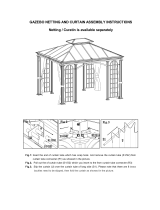
Manual
for
Marquee 10x15 m
PRO+ EventZone

2
Table of contents
Page
1. Introduction 004
1.1 General 005
1.2 Tools for assembly 006
2. Aligning the marquee and the base plate 007
2.1 Laying the base plates 007-008
3. Pre
-assembly 009
3.1 Pre-assembly of posts, bars and braces 010-012
3.2 Assembling the braces 013-014
4. Assembling the marquee 015
4.1 Installation of the tie frame 015-018
4.3 Assembling the pediment support 017
5. Assembly of the covers 019
5.1 Roof covers 020-021
5.2 Side and pediment covers 022-023
5.3 Pediments 024
5.4 (If required) Assembling the foot tubes 024-025
6. Dis
assembly 026
7. Warning instructions 027
7.1 Marquee construction 027
7.2 Transport and storage 027
7.3 Routine visual inspections 027
8. Technical data 028
8.1 Marquee construction 028
8.2 Covers 029
8.3 Standards 029

3
1.Introduction
The following assembly manual describes the installation and assembly
of your marquee by using systematic structure.
Please follow the instructions continuously and execute step by step.
Certain points have additional information if required.
!!!Attention!!!
Please follow accident prevention regulations
Ensure that there is no cable, pipes etc. below the
marquee!!!
On the structure of this assembly manual:
Drawings and sketches are used to explain individual steps for the
assembly and to identify individual components.
Drawings and sketches should be understood as principle
representation and thus they do not necessarily correspond to
the actual dimensions. Supplementary comments are also provided,
where required, to provide a better understanding.

4
1.1 General
Please read this manual thoroughly before starting assembly. Perform
the assembly stop only if all the points are clear, the components are
identified and follow the sequence.
Please follow accident prevention regulations.
Improper handling, non-adherence of rules may result in mortal injury.
Follow the sequence of this assembly manual.
At least 4 persons are required for installing the marquee.
Safety instructions:
- Ensure that all the eaves are correctly mounted.
- Rope braces must be tightened loosely after assembly.
- Defective or damaged components must be replaced immediately with
original spare parts.
- Removal of diagonal braces is forbidden.
- Secure all the bolts after assembly so that they do not slide out.
- Wear protective clothing (e.g. gloves) to prevent injuries.
- Use the supplied tools for assembly.
Please note:
The model approval (test log) contains requirements, specifications,
conditions and operating instructions for "mobile constructions". It should
be kept at the installation location for review by relevant authorities if
required. Each new installation should be communicated to the relevant
authorities.
In addition, the "Guidelines for the construction and operation of mobile
constructions", accident prevention regulations as well as relevant safety
regulations and standards shall be applicable (trade association). These
regulations must be strictly followed.
Assembly helpers should be instructed about possible hazard before they
start the assembly. At least one expert (supervisor) should take
responsibility for supervision during installation and removal. Expert here
means that the person has knowledge of the work processes and the
required safety measures.

5
1.2 Tools for assembly
Assembly and disassembly should always be done with appropriate
Assembly tools.
An assembly rod, see image 1, is supplied with each marquee.
Additional Site tools and equipment:
3 x towing rope snap hooks (load capacity at least 250 kg)
------------------------------------------------------------------------------------------------
2 x ratchet or wrench
------------------------------------------------------------------------------------------------
2 x ladder
------------------------------------------------------------------------------------------------
1 x sledgehammer / ground anchor impact tool
------------------------------------------------------------------------------------------------
1 x tape measure
------------------------------------------------------------------------------------------------
1 x pipe wrench
------------------------------------------------------------------------------------------------
1 x machinist's hammer
------------------------------------------------------------------------------------------------
1 x line with 2x marquee length
------------------------------------------------------------------------------------------------
1 x forklift with telescopic jib (optional)
------------------------------------------------------------------------------------------------
1 x for disassembling the marquee: anchor snag (optional)

6
2.Aligning the marquee and the base plate
It is recommended to align the basic dimensions of the marquee to local
conditions such as road path, building front and similar.
Exact position should be followed when distributing and positioning the
base plate. Wrongly or inaccurately positioned base plates will make
further assembly difficult.
Required assembly tools and materials:
2.1 Aligning the base plates
Note: Keep the ground anchor protruding by approx. 5 cm so that later
readjustment is possible.
2.1.1 Select orientation front.
2.1.2 Stretch line (marquee length + 2m on each side).
2.1.3 Align 1st base plate parallel to the line according to Fig. 1 and strike
the ground nails.

7
2.1.4 Now stretch line for the marquee width and align at right angle
(exact alignment follows).
2.1.5 Measure marquee width from the centre of the 1st base plate to the
centre of the 2nd base plate, align base plate parallel to the line and fix
with ground anchors (see Fig. 2, page 9).
2.1.6 At the line for the marquee length, lay out the 3rd base plate in
parallel. Measure the exact truss distance (TD) from the centre of the 1st
base plate to the centre of the 3rd base plate and fix 3rd base plate with
ground anchors.
2.1.7 According to Fig. 2, measure TD between 1st base plate and 2nd
base plate and mark point B. Measure at the line between 1st base plate
and 3rd base plate and mark point A.
2.1.8 If there is a diagonal line between points A and B, then the right
angle is guaranteed, if not the line between the 1st and 2nd base plate
should be pushed such that the required dimension is achieved.
2.1.9 1. Readjust base plate if required and align again to the line. Check
the marquee width between 1st base plate and 2nd base plate once
again and fix 3rd base plate 3 with ground anchors.
2.1.10 Similarly align 4th. base plate to the line for the marquee length.
Measure exact TD between the centre of 3rd base plate to the centre of
the 4th base plate and fix 4th base plate ground anchors.
2.1.11 Repeat above steps until all the base plates of a marquee side are
fixed.
2.1.12 Starting from the 2nd base plate, align the base plate for the
opposite marquee side and fix with ground anchors.
2.1.13 It is recommended to carry out a final inspection of the marquee
dimension between the centres of four external base plates.

8
3. Preassembly

9
3.1 Pre-assembly of posts, bars and braces
Assembly of posts and bars
Combine and match all components according to Fig. 4 (page 9) and 5
(page 11).
Lay out the components according to the images and following
description.
3.1.1 Push the left and right bar into the ridge shoe and connect with
pivot pins / screws.
3.1.2 Insert the posts with the corresponding rail connectors into the bars
and bolt with pivot pins.
3.1.3 Insert the trusses (completely mounted posts and bars) into the
base plate, bolt with foot bolts and secure with clip connectors.
(Important: It should be ensured that the holes in the foot bolts for the clip
connector are on the outer side of the marquee due to later assembly of
the foot tube.
3.1.4 Place and lay out pediment support / crossbeams at the respective
end trusses.
3.1.5 Sort and lay out flex holders (intermediate rails), ridge and eave
rails.

10

11

12
3.2 Assembling the braces
Braces should always be mounted (see image 6) and should be removed
only during the disassembly of the marquee.
The braces consist of diagonally arranged ropes in the roof and
walls, alternatively cross braces or diagonal struts can also be used
based on statics.
The braces should be mounted in the first and last brace field of the
marquee.
There can be maximum 6 braceless fields between the braces. The wall
braces are decisive in this regard. If the numbers of braceless fields
are exceeded, additional braces should be installed and this number
should not be exceeded. Arrangements of brace fields see Fig. 6
Fundamental information on assembly
The ropes of the braces should be mounted such that the turnbuckles are
always placed at the lower end of the rope. For pre-assembly, the roof
braces are only fixed to a strut.
3.3.1 Keep the ropes of the braces ready for the corresponding fields
according to image 7.
3.3.2 Screw turnbuckles of the ropes (do not unscrew) and put up
shackle.
3.3.3 Mount the ring screws of the roof braces to the ridge shoes and
tighten.
3.3.4 Plug ring screws at the end strut from above and counter nut, plug
ring screw at the inner strut from below and counter nut from above and
put up shackle.
3.3.5 Mount the wall braces with corresponding screws to the first brace
and screw in the specified
holes.

13

14
4. Assembling the marquee
4.1 Installation of the truss frame
4.1.1 Align the first pre-assembled trusses with the wall braces, position
one person each at the posts for securing the truss.
4.1.2 Likewise, place the second pre-assembled truss vertically (Image
7).
4.1.3 Fix the wall braces already mounted at the first truss with screws
and nuts to the second brace.
4.1.4 Mount the eave rails with the curved hook to the first truss into the
truss. (Image 8, page 16)
4.1.5 Mount the side with straight hook to the second truss with the help
of assembly rod. (Image 8, page 16)
4.1.6 Mount the ridge rail to the first truss with curved hook.
4.1.7 Mount the ridge rail to the second truss with straight hook.
Mount assembly fork
4.1.8 If the marquee design is available (depending on the marquee
width) mount the flex holder (intermediate rails) just like ridge and eave
rails.
4.1.9 Mount roof wind braces to the second truss and clamp loosely with
turnbuckle. (Image 9, page 18)
4.1.10 Install the remaining frame trusses as described in 4.1.2, 4.1.4 to
4.1.7. For the braces on other pediment side, the intermediate braces
should be installed as described in point 4.1.3 and 4.1.8.

15

16
4.3 Assembling the pediment supports
Note:
Depending on the marquee width, multiple pediment supports may be
required and should be installed according to the drawings.
4.3.1 Place the pediment support vertically below the ridge shoe /bar of
the corresponding end bar and insert into the intake at the ridge shoes
and screw. (Image 5, page 11)
4.3.2 Insert pediment support into the base plate and adjust with
telescope if required (loose the screw for this) and ensure that the
pediment support is even in the base plate.
4.3.3 Fix base plate with ground anchors.

17

18
5.Assembling the covers
Before assembling the cover, all the ground anchors must be placed
deep and all braces must be installed and clamped loosely.
Important: Do not pull the covers with raw force, because noticeable
resistance could also indicate inaccurate alignment in the assembly. If
required, pull back again and try or check the accuracy of the assembly.
5.1 Roof covers
5.1.1 Throw one pulling ropes each from left to right over the ridge of the
first brace field (image 9 above, page 18), assembly fork will be useful
here.
5.1.2 Pull both the other pulling ropes over the ridge by using this rope.
5.1.3 Mount roof covers (image 10, page 20), ensure correct position and
readjust if needed.
5.1.4 Suspend both the pulling ropes into the two outer eyelets of the roof
cover using snap hooks opening facing upwards. Pull back the 3rd Mount
pulling rope into the drawbar eyelet as pulling rope (image 10).
5.1.5 Lift the roof cover to piping channel height by pulling the pulling
ropes from the opposite side of the marquee and insert the left and right
piping of the covers into the piping channel of the bar.
(Image 10, page 20)
5.1.6 Place the roof cover into the roof bar at both the pulling ropes with
uniform pulling.
Important Pull the cover over the ridge in single pull.
5.1.7 Once the cover is pulled over bar completely, the two pulling ropes
will loosened and mounted in the 3rd rope, which was pulled with the
cover over the ridge. Pull back the 3rd rope so that both the other pulling
ropes are in initial position.
5.1.8 Repeat points 5.1.1 to 5.1.7 for other roof covers.

19
5.1.9 Once all the roof covers are fixed in the bars, these will be
tensioned with corresponding tensionless (belt, pressure, fix, expander
etc.).

20
/