Page is loading ...

Form No. 10174SL Rev B
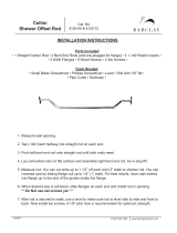
ProCore
®
SR Series
(Models SR48, SR54, SR54-S, SR70, SR70-S,
SR72 and SR75)
Original Instructions (EN)

Revision History
Revision
Date
Description
--
2010
Initial Issue
A
02/2018
Added revision history.
B
07/2020
Updated Chassis chapter.
©
THE TORO COMPANY 2020
This document and all information contained herein is the sole property of The Toro Company (and/or its affiliated companies). No
intellectual property rights are granted by the delivery of this document or the disclosure of its content. This document shall not be
reproduced by a third party without the express written consent of The Toro Company (and/or the appropriate affiliated company).

Reader Comments
The Toro Company Technical Assistance Center maintains a continuous effort to improve the quality
and usefulness of its publications. To do this effectively, we encourage user feedback.
Please comment on the completeness, accuracy, organization, usability, and readability of this manual
by an e-mail to [email protected]
or Mail to:
Technical Publication Manager, Commercial
The Toro Company
8111 Lyndale Avenue South
Bloomington, MN 55420-1196
Phone: +1 952-887-8495

NOTES _
Part No. 10174SL (Rev. B)
Service Manual
ProCore
R
SR Series
Preface
The purpose of this publication is to provide the service
technician with information for troubleshooting, testing
and repair of major systems and components on the
ProCore SR series deep tine aerators: models SR48,
SR54, SR54--S, SR70, SR70--S, SR72 and SR75.
REFER TO THE OPERATOR’S MANUAL FOR OPER-
ATING, MAINTENANCE AND ADJUSTMENT
INSTRUCTIONS. For reference, insert a copy of the
Operator’s Manuals and Parts Catalog for your machine
into Chapter 2 of this service manual. Additional copies
of the Operator’s Manuals and Parts Catalog are avail-
able on the internet at www .Toro.com.
The Toro Company reserves the right to change product
specifications or this publication without notice.
This safety symbol means DANGER, W ARNING,
or CAUTION, PERSONAL SAFETY INSTRUC-
TION. When you see this symbol, carefully read
the instructions that follow. Failure to obey the
instructions may result in personal injury.
NOTE: A NOTE will give general information about the
correct operation, maintenance, service, testing or re-
pair of the machine.
IMPORTANT: The IMPORTANT notice will give im-
portant instructions which must be followed to pre-
vent damage to systems or components on the
machine.
E The Toro Company -- 2011, 2018, 2020

ProCore SR Series
This page is intentionally blank.

ProCore SR Series
Table Of Contents
Chapter 1 -- Safety
Safety Instructions 1 -- 2..........................
Safety and Instruction Decals 1 -- 4................
Chapter 2 -- Product Records and Maintenance
Product Records 2 -- 1...........................
Maintenance 2 -- 1...............................
Equivalents and Conversions 2 -- 2................
Torque Specifications 2 -- 3.......................
Chapter 3 -- Chassis
General Information 3 -- 1........................
Service and Repairs 3 -- 2........................
Chapter 4 -- Coring Head (SR54 & SR70)
Specifications 4 -- 2..............................
General Information 4 -- 4........................
Special Tools 4 -- 7..............................
Service and Repairs 4 -- 8........................
Chapter 5 -- Coring Head (SR48 & SR72)
Specifications 5 -- 2..............................
General Information 5 -- 4........................
Special Tools 5 -- 6..............................
Service and Repairs 5 -- 8........................
Chapter 6 -- Coring Head (SR75)
Specifications 6 -- 2..............................
General Information 6 -- 4........................
Special Tools 6 -- 6..............................
Service and Repairs 6 -- 8........................
Chapter 7 -- Gearbox Service
General Information 7 -- 1........................
Service and Repairs 7 -- 2........................
SafetyProduct Records
and Maintenance
ChassisCoring Head
(SR54 & SR70)
Coring Head
(SR48 & SR72)
Coring Head
(SR75)
Gearbox
Service

ProCore SR Series
This page is intentionally blank.

ProCore SR Series Page 1 -- 1 Safety
Chapter 1
Safety
Table of Contents
SAFETY INSTRUCTIONS 2......................
Before Operating 2............................
While Operating 3.............................
Maintenance and Service 3....................
SAFETY AND INSTRUCTION DECALS 4..........
Safety
ProCore SR SeriesPage 1 -- 2Safety
Safety Instructions
The ProCore SR series of deep tine aerators are de-
signed and tested to offer safe service when operated
and maintained properly. Although hazard control and
accident prevention partially are dependent upon the
design and configuration of the machine, these factors
are also dependent upon the awareness, concern and
proper training of the personnel involved in the opera-
tion, transport, maintenance and storage of the ma-
chine. Improper use or maintenance of the machine can
result in injury or death. To reduce the potential for injury
or death, comply with the following safety instructions.
WARNING
To reduce the potential for injury or death, com-
ply with the following safety instructions.
Before Operating
1. Review and understand the contents of the Opera-
tor’s Manual before starting and operating the vehicle.
Become familiar with the controls and know how to stop
the vehicle and engine quickly. Additional copies of the
Operator’s Manual are available on the internet at
www.Toro.com.
2. Keep all shields, safety devices and decals in place.
If a shield, safety device or decal is defective, illegible
or damaged, repair or replace it before operating the
machine.
3. Make sure that the tractor is carefully selected to as-
sure the best performance and safe operation of the
ProCore deep tine aerator.
4. Make sure that operator is familiar with safe tractor
operation.
5. T ighten any loose nuts, bolts or screws to ensure
machine is in safe operating condition.
6. Make sure that the ProCore deep tine aerator is
properly attached to tractor .

ProCore SR Series Page 1 -- 3 Safety
While Operating
IMPORTANT: To prevent damage to your ProCore
aerator during operation:
• Never operate ProCore aerator without tine
heads installed.
• Do not operate the tractor in reverse when the
ProCore aerator is lowered.
• Make sure aerator roller is on ground before op-
erating aerator . Never operate with the aerator in
the raised position.
• Never operate the tractor PTO in excess of 500
RPM.
1. Operator should be on the tractor when starting the
engine and when operating the aerator. Stay away from
the aerator coring head when it is engaged.
2. Before starting the engine on the tractor:
A. Apply the parking brake.
B. Make sure traction lever or transmission is in neu-
tral and PTO is disengaged.
C. Refer to Tractor Operator’s Manual for safe start-
ing procedures.
3. Do not run tractor engine in a confined area without
adequate ventilation. Exhaust fumes are hazardous
and could possibly be deadly.
4. If abnormal aerator vibration is detected, disengage
PTO and stop tractor immediately. Determine source of
vibration and correct problem(s) before resuming the
use of aerator.
5. While operating, the combination of the tractor and
the ProCore aerator may exceed noise levels of
85dB(A) at the operator position. Hearing protection is
recommended for prolonged exposure to reduce the po-
tential of permanent hearing damage.
6. Before leaving the operator’s position of the tractor:
A. Disengage PTO power to aerator and lower aera-
tor to the ground.
B. Apply parking brake on tractor . Stop engine and
remove key from ignition switch.
C. W ait for all moving parts to stop before leaving
the tractor.
Maintenance and Service
1. The Operator’s Manual provides information regard-
ing the operation, general maintenance and mainte-
nance intervals for your ProCore aerator. Refer to this
publication for additional information when servicing the
machine.
2. Before servicing or making adjustments to aerator,
disengage tractor PTO, position aerator on a level sur-
face and lower aerator to the ground. Apply tractor park-
ing brake, stop engine and remove key from the ignition
switch.
3. Make sure machine is in safe operating condition by
keeping all nuts, bolts and screws tight.
4. Use care when checking or servicing the coring
head: wear gloves and use caution.
5. Never step over the PTO shaft to reach other side of
aerator. Walk around the machine instead.
6. The friction clutch on the PTO driveshaft may be-
come hot during use. Make sure that clutch has cooled
before performing any service on the driveshaft.
7. Before disconnecting aerator from tractor , install
storage stand to aerator frame and park aerator on a
hard, level surface.
8. After servicing the aerator, be sure that all guards
and covers are properly installed and secured.
9. At the time of manufacture, the machine conformed
to all applicable safety standards. To assure optimum
performance and continued safety certification of the
machine, use genuine Toro replacement parts and ac-
cessories. Replacement parts and accessories made
by other manufacturers may result in non-conformance
with the safety standards, and the warranty may be
voided.
10.If major repairs are ever needed or assistance is de-
sired, contact an Authorized Toro Distributor.
Safety

ProCore SR SeriesPage 1 -- 4Safety
Safety and Instruction Decals
Numerous safety and instruction decals are affixed to
the ProCore SR series deep tine aerator. If any decal
becomes illegible or damaged, install a new decal. Part
numbers for replacement decals are listed in your Parts
Catalog. Order replacement decals from your Autho-
rized Toro Distributor.

ProCore SR Series Page 2 -- 1 Product Records and Maintenance
Chapter 2
Product Records and Maintenance
Table of Contents
PRODUCT RECORDS 1.........................
MAINTENANCE 1...............................
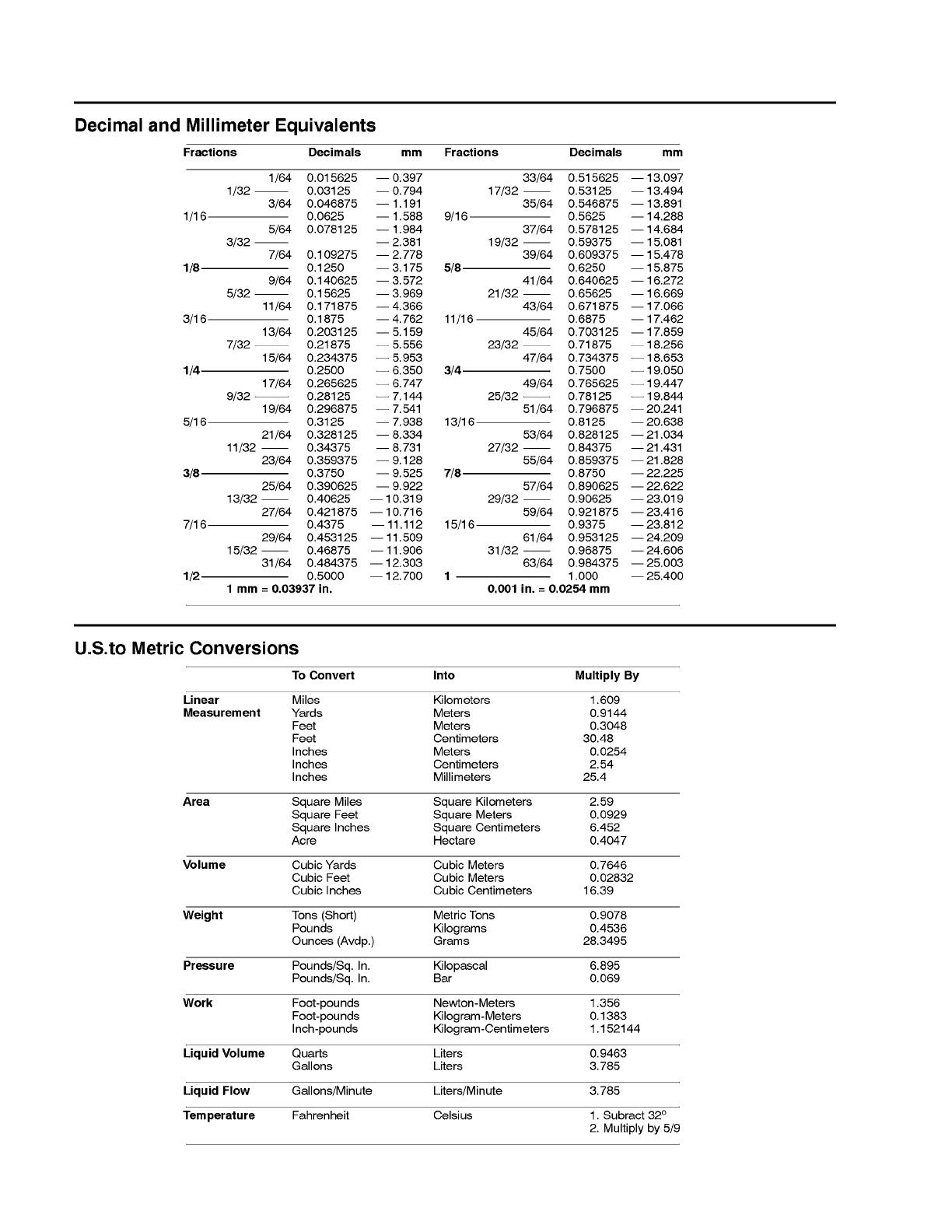
EQUIVALENTS AND CONVERSIONS 2...........
Decimal and Millimeter Equivalents 2............
U.S. to Metric Conversions 2...................
TORQUE SPECIFICATIONS 3....................
Fastener Identification 3.......................
Standard Torque for Dry, Zinc Plated and
Steel Fasteners (Inch Series) 4...............
Standard Torque for Dry, Zinc Plated and
Steel Fasteners (Metric Fasteners) 5...........
Other Torque Specifications 6..................
Conversion Factors 6..........................
Product Records
Insert Operator’s Manual and Parts Catalog for your
ProCore SR Series deep tine aerator at the end of this
chapter. Additionally, if any optional equipment or ac-
cessories have been installed to your ProCore, insert
the Installation Instructions, Operator’s Manuals and
Parts Catalogs for those options at the end of this chap-
ter.
Maintenance
Maintenance procedures and recommended service in-
tervals for the ProCore SR Series deep tine aerator are
covered in the Operator’s Manual. Refer to that publica-
tion when performing regular equipment maintenance.
Product Records
and Maintenance
0.09375
ProCore SR SeriesPage 2 -- 2Product Records and Maintenance
Equivalents and Conversions
ProCore SR Series Page 2 -- 3 Product Records and Maintenance
Torque Specifications
Recommended fastener torque values are listed in the
following tables. For critical applications, as determined
by Toro, either the recommended torque or a torque that
is unique to the application is c learly identified and spe-
cified in this Service Manual.
These Torque Specifications for the installation and
tightening of fasteners shall apply to all fasteners which
do not have a specific requirement identified in this Ser-
vice Manual. The following factors shall be considered
when applying torque: cleanliness of the fastener, use
of a thread sealant (e.g. Loctite), degree of lubrication
on the fastener, presence of a prevailing torque feature,
hardness of the surface underneath the fastener’s head
or similar condition which affects the installation.
As noted in the following tables, torque values should be
reduced by 25% for lubricated fasteners to achieve
the s imilar stress as a dry fastener. Torque values may
also have to be reduced when the fastener is threaded
into aluminum or brass. The specific torque value
should be determined based on the aluminum or brass
material strength, fastener size, length of thread en-
gagement, etc.
The standard method of verifying torque shall be per-
formed by marking a line on the fastener (head or nut)
and mating part, then back off fastener 1/4 of a turn.
Measure the torque required to tighten the fastener until
the lines match up.
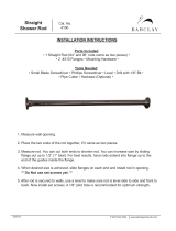
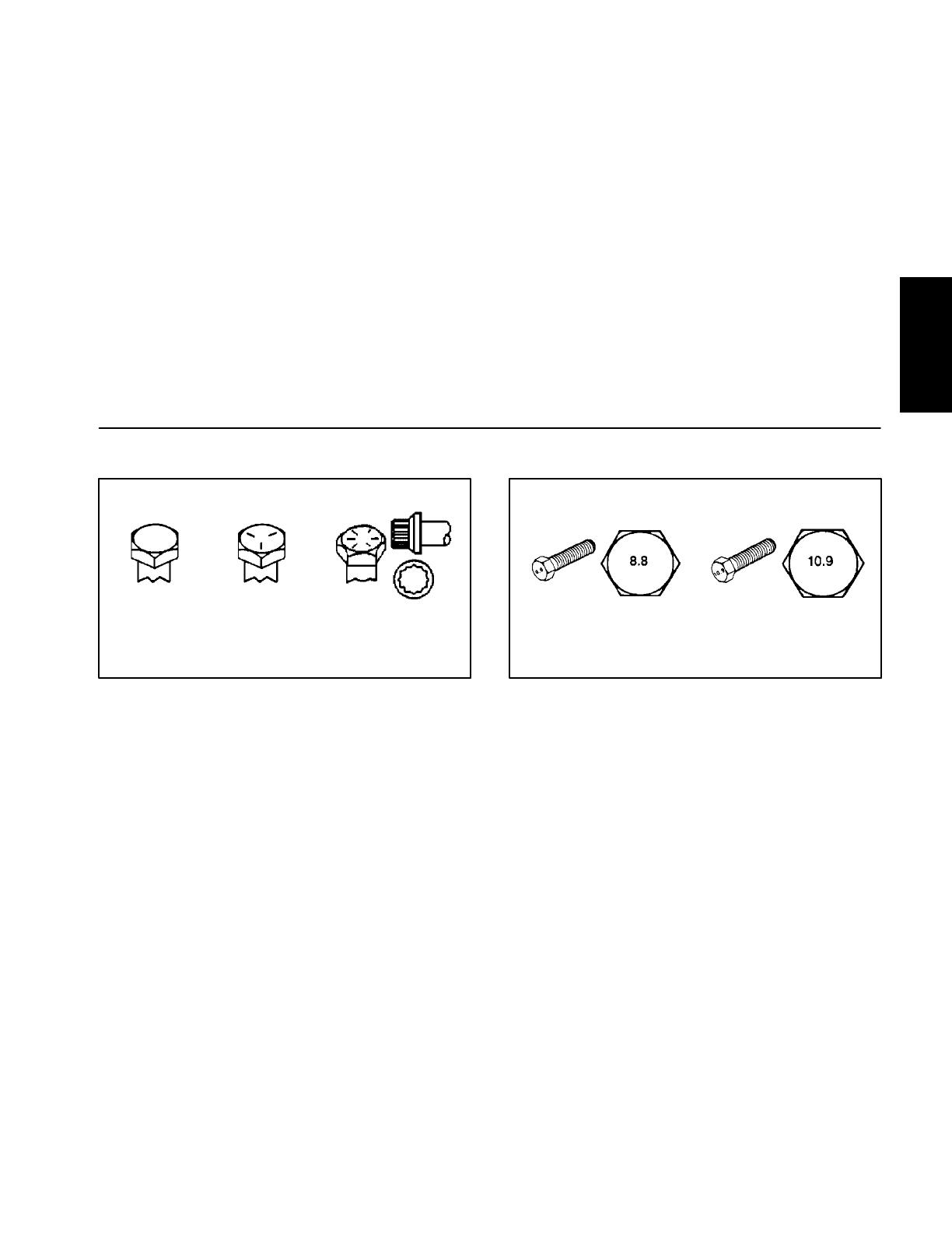
Fastener Identification
Figure 1
Grade 1 Grade 5 Grade 8
Inch Series Bolts and Screws
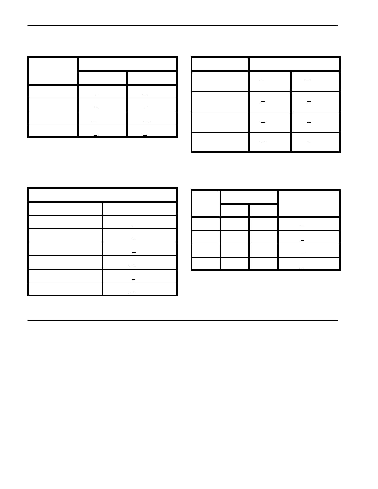
Figure 2
Class 8.8 Class 10.9
Metric Bolts and Screws
Product Records
and Maintenance

ProCore SR SeriesPage 2 -- 4Product Records and Maintenance
Standard Torque for Dry, Zinc Plated and Steel Fasteners (Inch Series)
Thread Size
Grade 1, 5 &
8withThin
Height Nuts
SAE Grade 1 Bolts, Screws, Studs &
Sems with Regular Height Nuts
(SAE J995 Grade 2 or Stronger Nuts)
SAE Grade 5 Bolts, Screws, Studs &
Sems with Regular Height Nuts
(SAE J995 Grade 2 or Stronger Nuts)
SAE Grade 8 Bolts, Screws, Studs &
Sems with Regular Height Nuts
(SAE J995 Grade 5 or Stronger Nuts)
in--lb in--lb N--cm in--lb N--cm in--lb N--cm
# 6 -- 32 UNC
1
0
+
2
1
3
+
2
1
4
7
+
2
3
15 + 2 170 + 20 23 + 2 260 + 20
# 6 -- 40 UNF
10 + 2 13 + 2 147 + 23
17 + 2 190 + 20 25 + 2 280 + 20
# 8 -- 32 UNC
1
3
+
2
2
5
+
5
2
8
2
+
3
0
29 + 3 330 + 30 41 + 4 460 + 45
# 8 -- 36 UNF
13 + 2 25 + 5 282 + 30
31 + 3 350 + 30 43 + 4 485 + 45
#10--24UNC
1
8
+
2
3
0
+
5
3
3
9
+
5
6
42 + 4 475 + 45 60 + 6 675 + 70
#10--32UNF
18 + 2 30 + 5 339 + 56
48 + 4 540 + 45 68 + 6 765 + 70
1/4 -- 20 UNC 48 + 7 53 + 7 599 + 79 100 + 10 1125 + 100 140 + 15 1580 + 170
1/4 -- 28 UNF 53 + 7 65 + 10 734 + 113 115 + 10 1300 + 100 160 + 15 1800 + 170
5/16 -- 18 UNC 115 + 15 105 + 17 1186 + 169 200 + 25 2250 + 280 300 + 30 3390 + 340
5/16 -- 24 UNF 138 + 17 128 + 17 1446 + 192 225 + 25 2540 + 280 325 + 30 3670 + 340
ft--lb ft--lb N--m ft--lb N--m ft--lb N--m
3/8 -- 16 UNC 16 + 2 16 + 2 22 + 3 30 + 3 41 + 4 43 + 4 58 + 5
3/8 -- 24 UNF 17 + 2 18 + 2 24 + 3 35 + 3 47 + 4 50 + 4 68 + 5
7/16 -- 14 UNC 27 + 3 27 + 3 37 + 4 50 + 5 68 + 7 70 + 7 95 + 9
7/16 -- 20 UNF 29 + 3 29 + 3 39 + 4 55 + 5 75 + 7 77 + 7 104 + 9
1/2 -- 13 UNC 30 + 3 48 + 7 65 + 9 75 + 8 102 + 11 105 + 10 142 + 14
1/2 -- 20 UNF 32 + 3 53 + 7 72 + 9 85 + 8 115 + 11 120 + 10 163 + 14
5/8 -- 11 UNC 65 + 10 88 + 12 119 + 16 150 + 15 203 + 20 210 + 20 285 + 27
5/8 -- 18 UNF 75 + 10 95 + 15 129 + 20 170 + 15 230 + 20 240 + 20 325 + 27
3/4 -- 10 UNC 93 + 12 140 + 20 190 + 27 265 + 25 359 + 34 375 + 35 508 + 47
3/4 -- 16 UNF 115 + 15 165 + 25 224 + 34 300 + 25 407 + 34 420 + 35 569 + 47
7/8 -- 9 UNC 140 + 20 225 + 25 305 + 34 430 + 45 583 + 61 600 + 60 813 + 81
7/8 -- 14 UNF 155 + 25 260 + 30 353 + 41 475 + 45 644 + 61 660 + 60 895 + 81
NOTE: Reduce torque values listed in the table above
by 25% for lubricated fasteners. Lubricated fasteners
are defined as threads coated with a lubricant such as
oil, graphite or thread sealant such as Loctite.
NOTE: Torque values may have to be reduced when
installing fasteners into threaded aluminum or brass.
The specific torque value should be determined based
on the fastener size, the aluminum or base material
strength, length of thread engagement, etc.
NOTE: The nominal torque values listed above for
Grade 5 and 8 fasteners are based on 75% of the mini-
mum proof load specified in SAE J429. The tolerance is
approximately +
10% of the nominal torque value. Thin
height nuts include jam nuts.

ProCore SR Series Page 2 -- 5 Product Records and Maintenance
Standard Torque for Dry, Zinc Plated and Steel Fasteners (Metric Fasteners)
T
h
r
e
a
d
S
i
z
e
Class 8.8 Bolts, Screws and Studs with
R
e
g
u
l
a
r
H
e
i
g
h
t
N
u
t
s
Class 10.9 Bolts, Screws and Studs with
R
e
g
u
l
a
r
H
e
i
g
h
t
N
u
t
s
Thread Size Regular Height Nuts
(Class 8 or Stronger Nuts)
Regular Height Nuts
(Class 10 or Stronger Nuts)
M5 X 0.8 57 + 5in--lb 640 + 60 N--cm 78 + 7in--lb 885 + 80 N--cm
M6 X 1.0 96 + 9in--lb 1018 + 100 N--c m 133 + 13 in--lb 1500 + 150 N--cm
M8 X 1.25 19 + 2ft--lb 26 + 3N--m 27 + 2ft--lb 36 + 3N--m
M10 X 1.5 38 + 4ft--lb 52 + 5N--m 53 + 5ft--lb 72 + 7N--m
M12 X 1.75 66 + 7ft--lb 90 + 10 N--m 92 + 9ft--lb 125 + 12 N--m
M16 X 2.0 166 + 15 ft--lb 225 + 20 N--m 229 + 22 ft--lb 310 + 30 N--m
M20 X 2.5 325 + 33 ft--lb 440 + 45 N--m 450 + 37 ft--lb 610 + 50 N--m
NOTE: Reduce torque values listed in the table above
by 25% for lubricated fasteners. Lubricated fasteners
are defined as threads coated with a lubricant such as
oil, graphite or thread sealant such as Loctite.
NOTE: Torque values may have to be reduced when
installing fasteners into threaded aluminum or brass.
The specific torque value should be determined based
on the fastener size, the aluminum or base material
strength, length of thread engagement, etc.
NOTE: The nominal torque values listed above are
based on 75% of the minimum proof load specified in
SAE J1199. The tolerance is approximately +
10% of the
nominal torque value.
Product Records
and Maintenance
ProCore SR SeriesPage 2 -- 6Product Records and Maintenance
Other Torque Specifications
SAE Grade 8 Steel Set Screws
T
h
r
e
a
d
S
i
z
e
Recommended Torque
Thread Size
Square Head Hex Socket
1/4 -- 20 UNC 140 + 20 in--lb 73 + 12 in--lb
5/16 -- 18 UNC 215 + 35 in--lb 145 + 20 in--lb
3/8 -- 16 UNC 35 + 10 ft--lb 18 + 3ft--lb
1/2 -- 13 UNC 75 + 15 ft--lb 50 + 10 ft--lb
Thread Cutting Screws
(Zinc Plated Steel)
Type 1, Type 23 or Type F
Thread Size Baseline Torque*
No. 6 -- 32 UNC 20 + 5in--lb
No. 8 -- 32 UNC 30 + 5in--lb
No. 10 -- 24 UNC 38 + 7in--lb
1/4 -- 20 UNC 85 + 15 in--lb
5/16 -- 18 UNC 110 + 20 in--lb
3/8 -- 16 UNC 200 + 100 in--lb
Wheel Bolts and Lug Nuts
Thread Size
Recommended Torque**
7/16 -- 20 UNF
Grade 5
65 + 10 ft--lb 88 + 14 N--m
1/2 -- 20 UNF
Grade 5
80 + 10 ft--lb 108 + 14 N--m
M12 X 1.25
Class 8.8
80 + 10 ft--lb 108 + 14 N--m
M12 X 1.5
Class 8.8
80 + 10 ft--lb 108 + 14 N--m
** For steel wheels and non--lubricated fasteners.
Thread Cutting Screws
(Zinc Plated Steel)
Thread
S
i
z
e
Threads per Inch
B
a
s
e
l
i
n
e
T
o
r
q
u
e
*
Size
Type A Type B
Baseline Torque
*
No. 6 18 20 20 + 5in--lb
No. 8 15 18 30 + 5in--lb
No. 10 12 16 38 + 7in--lb
No. 12 11 14 85 + 15 in--lb
* Hole size, material strength, material thickness & finish
must be considered when determining specific torque
values. All torque values are based on non--lubricated
fasteners.
Conversion Factors
in--lb X 11.2985 = N--cm N--cm X 0.08851 = in--lb
ft--lb X 1.3558 = N--m N--m X 0.7376 = ft--lb

ProCore SR Series Page 3 -- 1 Chassis
Chapter 3
Chassis
Table of Contents
GENERAL INFORMATION 1.....................
Operator ’s Manual 1..........................
SERVICE AND REPAIRS 2......................
Roller (ProCore SR54, SR54--S, SR70
and SR70--S) 2.............................
Roller (ProCore SR48 and SR72) 4.............
Roller (ProCore SR75) 6.......................
PTO Driveshaft 8.............................
PTO Driveshaft Clutch Service 10...............
PTO Driveshaft Cross and Bearing Service 12....
Hydraulic Top Link 13.........................
Covers (ProCore SR54, SR54--S, SR70
and SR70--S) 16............................
Covers (ProCore SR48 and SR72) 18...........
Covers (ProCore SR75) 20.....................
General Information
Operator’s Manual
The Operator ’s Manual provides information regarding
the operation, general maintenance and maintenance
intervals for your ProCore aerator. Refer to this publica-
tions for additional information when servicing the ma-
chine.
Chassis

ProCore SR SeriesPage 3 -- 2Chassis
Service and R epairs
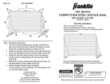
Roller (ProCore SR54, SR54--S, SR70 and SR70--S)
1. Aerator frame
2. Flange bearing (2 used)
3. Lock nut (2 used per bearing)
4. Roller
5. Single roller boot (2 used)
6. Lock washer (2 used)
7. Cap screw (2 used)
8. Lock washer (2 used)
9. Cap screw (2 used)
10. Scraper
11. Cap screw (2 used per bearing)
12. Cap screw (2 used)
13. Lock washer (2 used)
14. Flat washer (2 used)
Figure 1
FRONT
RIGHT
PROCORE SR54 SHOWN
ANTISEIZE
LUBRICANT
ANTISEIZE
LUBRICANT
2
3
6
8
9
10
11
13
1
5
7
12
14
4
NOTE: ProCore SR54 and SR 70 aerators use a single
roller with two (2) bolt flange bearings (Fig. 1). Models
SR54 --S and SR70--S use two (2) rollers each sup-
ported with two (2) bolt flange bearings (Fig. 2). The pro-
cedure for removal and installation of the rollers is the
same. The ProCore SR54 is shown in Figure 1.
Roller Removal (Fig. 1)
1. Position aerator on a firm, level surface with aerator
attached to tractor. Disengage PTO, apply tractor park-
ing brake, stop engine and remove key from the ignition
switch.
2. Support aerator to prevent it from moving.
3. Chock roller to prevent it from moving.
/