Page is loading ...

FormNo.3362-258RevA
ProCoreSR48,SR54,SR54–S,
SR70,SR70–S,SR72and
SR75–HDAerators
ModelNo.09920—SerialNo.290000001andUp
ModelNo.09921—SerialNo.290000001andUp
ModelNo.09922—SerialNo.290000001andUp
ModelNo.09924—SerialNo.290000001andUp
ModelNo.09925—SerialNo.290000001andUp
ModelNo.09926—SerialNo.290000001andUp
ModelNo.09927—SerialNo.290000001andUp
ToregisteryourproductordownloadanOperator'sManualorPartsCatalogatnocharge,gotowww.Toro.com.OriginalInstructions(EN)

Introduction
Readthisinformationcarefullytolearnhowtooperate
andmaintainyourproductproperlyandtoavoidinjury
andproductdamage.Youareresponsibleforoperating
theproductproperlyandsafely.
YoumaycontactTorodirectlyatwww .Toro.comfor
productandaccessoryinformation,helpndinga
dealer,ortoregisteryourproduct.
Wheneveryouneedservice,genuineToroparts,or
additionalinformation,contactanAuthorizedService
DealerorToroCustomerServiceandhavethemodel
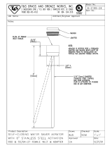
andserialnumbersofyourproductready.Figure1
identiesthelocationofthemodelandserialnumbers
ontheproduct.Writethenumbersinthespace
provided.
Figure1
1.Modelandserialnumberlocation
ModelNo.
SerialNo.
Thismanualidentiespotentialhazardsandhas
safetymessagesidentiedbythesafetyalertsymbol
(Figure2),whichsignalsahazardthatmaycauseserious
injuryordeathifyoudonotfollowtherecommended
precautions.
Figure2
1.Safetyalertsymbol
Thismanualuses2otherwordstohighlightinformation.
Importantcallsattentiontospecialmechanical
informationandNoteemphasizesgeneralinformation
worthyofspecialattention.
©2009—TheToro®Company
8111LyndaleAvenueSouth
Bloomington,MN55420
2
Contactusatwww.Toro.com.
PrintedintheUSA.
AllRightsReserved

Contents
Introduction.................................................................2
Safety...........................................................................4
SafeOperatingPractices.......................................4
SafetyandInstructionalDecals.............................6
Setup............................................................................8
1ConnectingtheLowerLinkArms......................9
2ConnectingtheHydraulicTopLink
(ModelsSR48,SR54,SR70,SR72and
SR75–HD........................................................9
3ConnectingtheTractorUpperLink(Models
SR54–SandSR70–S)......................................11
4VerifyingtheTopLinkSetUp..........................11
5CheckingthePTOAngle.................................12
6FittingthePTOshaft.......................................12
7InstallingthePTOShield.................................14
8ConnectingthePTOShaft...............................15
9AdjustingtheSwayLinks.................................16
10LevelingtheAeratorSide-to-Side...................17
11InstallingtheTines.........................................17
12RemovingtheStorageStands(Models
SR54,SR54S,SR70andSR70–S).....................18
13RemovingtheStorageStands(Models
SR72).............................................................18
ProductOverview......................................................19
Specications.....................................................19
Attachments/Accessories...................................19
Operation...................................................................20
TractorControls.................................................20
PrinciplesofOperation......................................20
TractorPTOSpeed............................................20
TrainingPeriod...................................................20
BeforeAerating..................................................20
AeratingProcedures...........................................21
OperatingTips...................................................21
SubsoilCultivation.............................................22
HardGround.....................................................22
Longer/LargerTines..........................................22
MultiRowAdapterHeads..................................22
RootZoneLifting..............................................22
AdjustingtheTineAngle....................................22
TransportOperation..........................................23
InspectionandCleanupafterUse........................23
Maintenance...............................................................24
RecommendedMaintenanceSchedule(s)................24
LiftingtheMachine............................................24
GreasingtheBearings.........................................25
CheckingtheGearboxOil..................................25
ChangingtheGearboxOil..................................26
Inspecting/AdjustingtheDriveChain................26
AdjustingthePTOClutch..................................27
CheckingtheCoringHeadFastener
Torque...........................................................27
CheckingtheSprings..........................................28
AdjustingtheHoleSpacing.................................28
RemovingtheAeratorfromtheTractor...............28
TroubleShooting...............................................29
Storage.......................................................................30
3

Safety
Improperuseormaintenancebytheoperatoror
ownercanresultininjury.Toreducethepotential
forinjury,complywiththesesafetyinstructions
andalwayspayattentiontothesafetyalert
symbol,whichmeansCAUTION,WARNING,or
DANGER-"personalsafetyinstruction."Failureto
complywiththeinstructionmayresultinpersonal
injuryordeath.
SafeOperatingPractices
BeforeOperating
•OwnersofthisAeratormustgiveoperatorsand
employeesfulloperationandsafetyinstructions
beforeallowingthemtooperatethismachineandat
leastannuallythereafter.Anoperatorwhohasnot
readandfullyunderstoodalloperatingandsafety
instructionsisnotqualiedtooperatethismachine.
Becomefamiliarwithallcontrolsandknowhowto
stopquickly.
•Donotallowchildrentooperatethemachine.Do
notallowadultstooperatethemachinewithout
properinstruction.
•Removealldebrisorotherobjectsthatmight
interferewithoperation.Keepallbystandersaway
fromtheworkarea.
•Locateandmarkallundergroundobstructionssuch
asirrigationcomponents,electricalortelephone
lines.
•Makesuretractorisinneutralandparkingbrake
appliedbeforestarting.RefertoTractorOperator’s
Manualforsafestartingprocedures.
•Ensurethatyourtractorissuitableforusewithan
implementofthisweightbycheckingwithyour
tractorsupplierormanufacturer.
•Mountingtheaeratortotherearofthetractor
willdecreasetheweightonthetractorfrontaxle.
Toassureadequatesteeringcontrolandstability
itmaybenecessarytoaddballasttothefrontof
thetractor.RefertoTractorOperator’sManualfor
ballastrequirements.
•Keepallshieldsandsafetydevicesinplace.Ifa
shield,safetydeviceordecalisdamaged,repairor
replaceitbeforeoperationiscommenced.Also
tightenanyloosenuts,boltsandscrewstoensure
machineisinsafeoperatingcondition.
•Donotoperatemachinewhilewearingsandals,
tennisshoes,sneakersorshorts.Also,donot
wearloosettingclothingwhichcouldgetcaught
inmovingparts.Alwayswearlongpantsand
substantialshoes.Wearingsafetyglasses,safety
shoes,hearingprotectionandahelmetisadvisable
andmayberequiredbysomelocalordinancesand
insuranceregulations.
WhileOperating
•Neveroperatethetractorinreversewhentheaerator
islowered.
•Keepallbystandersandpetsawayfromthework
area.
•Usingthemachinedemandsattention,andto
preventlossofcontrol:
–Useonlyindaylightorwhenthereisadequate
articiallight.
–Watchforholesorotherhiddenhazards.
–Donotoperatethemachineclosetoasandtrap,
ditch,creekorotherhazard.
–Reducespeedonsidehillsandbeforemaking
sharpturnstopreventtippingorlossofcontrol.
–Lookbehindtheaeratorbeforebackingup.
•Ifthetinesstrikeasolidobjectorthemachine
vibratesabnormally,disengagethePTO,setthe
parkingbrakeandshuttheengineoff.Removekey
fromignitionswitch.Checkaeratorandtractionunit
fordamage.Repairanydamagebeforerestartingthe
engineandoperatingthetines.Besuretinesarein
goodconditionandallboltsaretight.
•Beforeleavingmachineunattended,disengagepower
toaerator,loweraeratorontostoragestandsandset
parkingbrake.Stopengine.
•Neverdismountwhiletractorisinmotion.Never
getonorofftractorwhileengineisrunningand
PTOdriveshaftisengaged.NeverstepoverPTO
shafttoreachothersideofaerator-walkaround
themachine.
•Whenliftingtheaerator,disengagethePTOwhen
therollerisapproximately5”fromtheground.
•Donotoperatethismachinewithouttherolleron
theground.Neveroperatewiththemachinein
theraisedposition.
•Parktheaeratoronahard,levelsurface,installthe
aeratorstoragestandsbeforedisconnectingfrom
tractor.
•Ifitisnecessarytoprobebelowthesoilsurface,use
anonconductivematerialtopreventelectricalshock
incaseelectricalwiresarepresent.
•Alwayslowertheaeratortothegroundbefore
leavingthetractorunattended.Neverleavethe
aeratorintheraisedpositionwhenitisunattended.
4

Transporting
•Theaeratorisheavy.Whenattachedtoatractor
andintheraisedposition,itsweightwillaffect
stability,brakingandsteering.Exercisecautionwhen
transportingbetweenworkingareas.
•Alwaysmaintainpropertractortirepressure.
•Besureyouareincompliancewithallregulations
beforetransportingequipmentonthepublicroads
andhighways.Makesureallrequiredreectors
andlightsareinplaceandarecleanandvisibleby
overtakingandoncomingtrafc.
•Neverallowpassengerstorideonthemachine
duringtransport.
•Reducespeedonroughroadsandsurfaces
•Independentwheelbrakesshouldalwaysbelocked
togetherwhentransporting.
PTOShaft
•ForallPTOshaftsteelparts(tubes,bearings,joints
etc.)disassemblyorrepairs,itishighlyadvisable
tocontactyourlocalTorodistributor.Removalof
componentsforrepairsandreassemblymaydamage
somepartsifnotperformedwithspecialtoolsby
trainedtechnicians.
•ThePTOshaftmustnotbeusedwithouttheguards
supplied,withpartialprotectionorwithdamaged
guards.OnCEmachines,operationisprohibited
withoutthespecialanti-rotationchainscorrectly
installed,soastopermitthemaximumangleofthe
PTOshaftwithoutbreakingthechains.
•Frictionclutchesmaybecomehotduringuse.Do
nottouch.Toavoidtheriskofre,keepthearea
aroundtheclutchfreeofammablematerialand
avoidprolongedslippingoftheclutch.
Maintenance
•Beforemakingadjustmentsorperforming
maintenanceontheaerator,switchofftheengine,
stopthePTOandapplytheparkingbrakebefore
dismountingfromthetractor.Besuretheaeratoris
onthegroundorloweredontothesafetystands.
•Supportthemachinewiththeblocks,jacksoron
storagestandswhenworkingbeneathit.Never
relyonthetractor’shydraulicstosupportthe
machine.
•Placeallcontrolsinneutral,stoptheengine,apply
parkingbrakeandwaitforallmovingpartsto
stopbeforeservicing,maintaining,adjustingor
unblockingtheaerator.
•Besurethemachineisinsafeoperatingconditionby
keepingnuts,boltsandscrewstight.Checkthetine
mountingboltsdailytobesuretheyaretightened
tospecication.
•Donotcheckoradjustthechaintensionwhenthe
tractorengineisrunning.
•Besureallguardsarereplacedandthehoodis
securedshutaftermaintainingoradjustingthe
machine.
•Performonlythosemaintenanceinstructions
describedinthismanual.Ifmajorrepairsare
everneededorassistanceisdesired,contactan
AuthorizedToroDistributor.Toensureoptimum
performanceandsafety,alwayspurchasegenuine
Tororeplacementpartsandaccessoriestokeepthe
ToroallToro.Neveruse"will-t"replacementparts
andaccessoriesmadebyothermanufacturers.Look
fortheTorologotoensuregenuineness.Using
unapprovedreplacementpartsandaccessoriescould
voidthewarrantyofTheToroCompany.
StorageSafety
•Storetheaeratoronthestoragestandspositionedon
armlevelsurface.
•Storetheaeratorawayfromareasofhumanactivity.
•Donotallowchildrentoplayonoraroundthe
storedmachine.
•Makesuretheaeratorispositionedonrmandsolid
groundsoitdoesnotsinkortipover.
5

SafetyandInstructionalDecals
Safetydecalsandinstructionsareeasilyvisibletotheoperatorandarelocatednearanyareaof
potentialdanger.Replaceanydecalthatisdamagedorlost.
117–7052
1.ReadtheOperator’sManual,donotoilthechaindrive.
100–3612
1.Entanglementhazard—stayawayfrommovingparts,keep
allguardsandshieldsinplace.
110-4668
1.Entanglementhazard,shaft—stayawayfrommovingparts.
2.PTOspeedandinputdirection.
3.Usecliptosecurelashcablewhennotinuse.Uselash
cabletosupportthepowertake-offwhenthemachineis
disconnectedfromtractor.
117–7051
1.Crushinghazardofhandorfoot—keepbystandersasafe
distancefromthemachine.
117–7050
1.Warning—readtheOperator’sManual.
2.Warning—removetheignitionkeyandreadtheinstructionsbeforeservicingorperformingmaintenance.
3.Warning—donotoperatethismachineunlessyouaretrained.
4.Entanglementhazard,belt—stayawayfrommovingparts,keepallguardsinplace.
5.Crushinghazardofhandorfoot—keepbystandersasafedistancefromthemachine.
6.Crushinghazardofhandandbody—supportmachineonstandwhennotinuse.
7.Fallinghazard—donotcarrypassengers.
6

92–1581
92–1582
7

Setup
LooseParts
Usethechartbelowtoverifythatallpartshavebeenshipped.
ProcedureDescription
Qty.
Use
Hitchpin2
1
Lynchpin2
ConnectLowerLinkArms
Hydraulictoplink1
Hydraulichose,3–1/2feet
1
Hydraulichose,2–1/2feet
1
Extensionbracket2
Rotationalbracket1
2
Hosequickcouplings(notincluded)
2
ConnectHydraulicT opLink
Springloadedtoplink
1
Linkpin3
3
Lynchpin3
ConnectUpperLink
4
Nopartsrequired
–
Verifythetoplinksetup
5
Nopartsrequired
–
CheckingthePTOangle
6
PTOshaft
1
FittingthePTOshaft
7
PTOShield
1
InstallthePTOShield
Pin(suppliedwithPTOshaft)
1
8
Nut(suppliedwithPTOshaft)
1
ConnectPTOShaft
9
Nopartsrequired
–
AdjustingSwayLinks
10
Level(notsupplied)
1
LevelAeratorSide-to-Side
11
Tines
A/R
InstalltheTines
12
Nopartsrequired
–
RemoveStorageStands
13
Nopartsrequired
–
RemoveStorageStands
8

MediaandAdditionalParts
Description
Qty.
Use
Operator’sManual
1
Readbeforeoperatingtheaerator
PartsCatalog
1
Usetoreferencepartnumbers
SpringWires-SR54
6Replacementspringwires
SpringWires-SR70
8Replacementspringwires
SpringWires-SR72
4Replacementspringwires
SpringWires-SR72
2Replacementspringwires
Allenwrench1
TineheadboltwrenchforSR72
PTOOperatorsManual
1
Readbeforeoperatingtheaerator
1
ConnectingtheLowerLink
Arms
Partsneededforthisprocedure:
2Hitchpin
2Lynchpin
Procedure
1.Removetheboltssecuringtheaeratorstoragestands
totheshippingpalletandremovetheaeratorfrom
thepallet.
2.Theaeratormustbepositionedonaat,level
surfaceforinstallation.
3.Backthetractorsquarelyuptotheaeratoruntil
thelowerlinkarmsarealignedwiththemounting
brackets.
4.MakesurethePTOisdisengaged.
5.Engagetheparkingbrake,STOPtheengineand
removethekeyfromtheignition.Waitforthe
engineandallmovingpartstoSTOPbeforeleaving
theOperator’sseatonthetractor.
Note:Formaximumgroundclearance,thehitch
pinsshouldbesecuredintheaeratorlowermounting
bracketholes,whensoequipped.Todetermine
whentousetheuppermountingholes,referto
ConnectingthePTOShaft.
6.Securethelowerlinkarmstotheaeratormounting
bracketswitheitherlynchpins(Figure3)orhitch
pinsandlynchpins(Figure4).
Figure3
1.Lowerlink2.Lynchpin
Figure4
1.Hitchpin3.Lowerlink
2.Aeratormountingbracket
9

2
Connectingthe
HydraulicTopLink
(ModelsSR48,SR54,SR70,
SR72andSR75–HD
Partsneededforthisprocedure:
1Hydraulictoplink
1
Hydraulichose,3–1/2feet
1
Hydraulichose,2–1/2feet
2Extensionbracket
1Rotationalbracket
2
Hosequickcouplings(notincluded)
Procedure
Thetractormustbeequippedwithadoubleactingspool
valvewithanoperatorcontrolleverandtwo1/2”(12.7
mm)quick-releasecouplingsattherearofthetractor.It
isalsonecessaryforyoutoprovidetwoquickcouplings
tottothehydraulictoplinkhoses(1/2–14NPTF
hoseendthreadsize).
1.Securetheconnectinglinkendofthehydraulictop
linktothetractorwiththepinssuppliedwiththe
tractor(Figure5).Positionthehydraulictoplinkso
therodendistowardtheaerator.Thecylinderports
shouldbepositionedtowardthetractor’sauxiliary
powerhydraulics.
Note:Ifthehydrauliccylindermustbepositioned
withtheportsfacingupward,usetherotational
blockinsteadofthestandardmountingblockto
repositionthecylinder(Figure5).
Installtherotationalblockasfollows:
A.Removethecotterpinandpinsecuring
thestandardconnectinglinktothecylinder
(Figure5).Removetheconnectinglinkfromthe
cylinder.
B.Installtherotationalblocktothecylinderwith
thepinspreviouslyremoved(Figure5).
Figure5
1.Aeratorhitchpin7.Tractorlinkpin
2.Hydraulictoplink
8.Clevis&lynchpin
3.Rotationalblock
9.2–1/2foothydraulichose
4.Connectinglink10.3–1/2foothydraulichose
5.3inchextensionblock
11.Hosequickcouplings(not
included)
6.5inchextensionblock12.Tractorhydraulicports
2.Connectthe3–1/2footlonghydraulichosetothe
hydraulictoplinkportwhichisclosesttotheaerator
Figure5.ApplyTeontapeorpipethreadsealantto
thehosethreadstopreventanyleaks.
3.Connectthe2–1/2footlonghydraulichosetothe
hydraulictoplinkportwhichisclosesttothetractor
(Figure5).ApplyTeontapeorpipethreadsealant
tothehosethreadstopreventanyleaks.
4.Installquickcouplings(notincluded)tothehydraulic
hoses(1/2–14NPTFhoseendthreadsize).
5.Connectthetwohydraulichosequickcouplingsto
theportsprovidedonthetractor.
6.Startthetractorengineandoperatethetractorspool
valvetochecktheextendandretractmotionofthe
hydraulictoplink.
Note:Reversethehoseconnectionsiftheydono
agreewiththetractorcontroloperation.
7.Securetherodendofhydraulictoplinktothemost
forwardholepossibleintheaeratorbracketwithlink
pinandlynchpin(Figure6).
Important:Whensecuringtherodendof
thehydrauliclink,makesuretousethemost
forwardmountingholesinthemountingbracket
sothereisenoughclearanceforthebarrelofthe
cylinderwhenretracted.
10

Figure6
1.Rodendofcylinder4.Aeratorbracket(forward
holes)
2.Lynchpin5.Linkpin
3.Linkpin
Ifthehydrauliccylinderdoesnotreachtheaerator
mountingbracket,useanextensionblockinsteadof
thestandardmountingblocktoconnectthecylinder
tothetractor(Figure5).
Installtheextensionblocksasfollows:
A.Removethecotterpinandpinsecuring
thestandardconnectinglinktothecylinder
(Figure5).Removetheconnectinglinkfromthe
cylinder.
B.Installtherequiredlengthextensionblockto
thecylinderwiththepinspreviouslyremoved
(Figure5).
3
Connectingthe
TractorUpperLink
(ModelsSR54–SandSR70–S)
Partsneededforthisprocedure:
1
Springloadedtoplink
3Linkpin
3Lynchpin
Procedure
1.Mountthespringloadedtoplinktotheaerator
bracketwithtwolinkpinsandlynchpins(Figure7)
2.Loosenthelocknutonthetractorupperlink.Adjust
theupperlinkuntilitalignswiththeclevisonthe
springloadedtoplinkoftheaerator(Figure7).
Figure7
1.Springloadedtoplink
4.Lynchpin
2.Upperlink5.Locknut
3.Linkpin
3.Connectthetractorupperlinktotheclevisonthe
springloadedtoplinkandsecurewithalinkpinand
lynchpin(Figure7).
4.Greasethethreadedsteelupperlinktubes.
5.Measurethelengthofthespringinthetoplink.
6.Rotatetheupperlinkuntilthespringiscompressed
byabout1/2inch(Figure7).
7.Tightenthelocknuttosecuretheupperlinkinto
position.
11

4
VerifyingtheTopLinkSetUp
NoPartsRequired
Procedure
•Extendingthehydrauliccylinderwillincreasethe
tinedepth.
•Fullyextendthehydrauliccylindertodetermine
thelocationofthetineheadsandtoverifyifthey
contacttheground.
Ifthetineheadscontacttheground,turf
damagewilloccur.
Note:Onundulatingturf,theoperatorcanadjust
thecylindertomaintaintinedepth(crestingahill)
butitwillbenecessarytohavethetineheadsset
about2inchesbelowground.
•Ifthetineheadscontacttheground,adjustthe
locationofthecylinderendstomovethetopofthe
aeratorclosertothetractor.
•Ifthetineheadsdonotcontacttheground,
extensionbrackets(includedwithaerator)canbe
installedtothetoplinktomovethetineheadscloser
totheground.
Important:WhenconnectingthePTO,besure
thattheaeratorisnotbeingliftedhigherthanis
necessary.Liftingthemachinetoohighwillcause
thePTOshaftknucklestobreak(Figure8).Never
leavethePTOturningwhentheaeratorislifted.
ThePTOcanbeoperateduptoanangleof25º,but
canneverexceeda35ºanglewhentheaeratoris
atitshighestpositionorsevereshaftdamagemay
occur.
Figure8
1.Breakagewilloccurhere
5
CheckingthePTOAngle
NoPartsRequired
Procedure
Withtheaeratorpositionedonthegroundandlowered
tothedeepestlocation,checktheanglebetweenthe
PTOandtheaerator.Makesurethetinesareremoved
beforeperformingthisoperation.
Lifttheaeratorandfullyretractthehydraulictoplink
cylinder.ChecktheanglebetweenthePTOandthe
aerator.Ifthisangleisgreaterthan35degrees,make
adjustmentstothetractorsothattheaeratorcannotbe
liftedpast35degrees.Thiscanbeaccomplishedby
usingthetractorliftstop(ifsoequipped)ormovingthe
lowerlinkstoahighermountinghole(ifsoequipped).
6
FittingthePTOshaft
Partsneededforthisprocedure:
1
PTOshaft
Procedure
1.Movethetractorandaeratortoalevelsurface.
2.Raisetheaeratorcompletelyandfullyretractthetop
linkcylinderorupperlink(Figure9).
12

Figure9
3.Measurethedistancefromthereliefontheendof
thetractorPTOshafttothereliefontheaerator
gearboxPTOshaft(Figure10).Recordthisdistance.
Example:26.5inches(67cm).
Figure10
1.Measurehere
4.Lowertheaeratortothegroundandfullyextendthe
toplinkcylinderorupperlink(Figure11).
Figure11
5.Measurethedistancefromthereliefontheendof
thetractorPTOshafttothereliefontheaerator
gearboxPTOshaft(Figure12).Recordthisdistance.
Example:27.5inches(70cm).
Figure12
1.Measurehere
6.OnthePTOshaft,measurethedistancefromthe
centeroflockingpinballononeendtothecenterof
thelockingpinbuttonontheotherend(Figure13).
Recordthisdistance.Example:32inches(81cm).
Figure13
1.Measurehere
7.Usingthesmallerofthetwomeasurementsin
Figure12andFigure10,subtractthatdistancefrom
thedistanceinFigure13.Example32(81cm)inches
minus26.5inches(67cm)equals5.5inches(14cm).
8.Theexamplemeasurementsshowthattheshaftis
5.5inchestoolong.Nowyouwillneedtoaddan
extra1/2inch(1.2cm)tobesurethatthePTOshaft
willnotbottomoutwhentheaeratorisliftedtoits
highestposition.
Example:5.50inches(14cm)plus1/2inch(1.2cm)
equals6.00inches(15cm).
9.SlidethePTOshafttubestogetheruntiltheyare
fullycollapsed.Verifythattheinsidetubedoesnot
protrudeintothecrossandbearingsectionofthe
outertube(Figure14).Ifthishappens,cutmoreoff
theinsidetube,tocorrecttheproblem.
13

Figure14
1.Insidetube
10.SeparatethetwohalvesofthePTOshaft(Figure15,
illustration1).
11.Measurethedistancefromtheendofeachtubeto
itssafetyshield(Figure15,illustration1).Record
thedistances.
Figure15
1.Measurehere
12.Usingthedimensionsdeterminedinstep8,locate,
markandcutofftheshieldandtubefromeachPTO
half(Figure15,illustrations2&3).
Note:Morewillhavetobecutofftheinsidetube
onlyifitisprotrudingintothecrossandbearing
sectionoftheoutertube.
13.Usingthedimensionsdeterminedinstep11,locate,
markandcutoffjustthesafetyshieldstoexposethe
tubesFigure15—illustrations4&5.
14.Carefullydeburrtheendsofthetubeswithaleand
removeallthelingsfromthetubes.
15.Greasetheinsidetube.
Note:Telescopingtubesmustalwaysoverlapby
1/2oftheirlengthinnormaloperationandatleast
1/3oftheirlengthinallworkingconditions.During
transport,whenthedrivelineisnotrotating,the
telescopingtubesmusthaveasuitableoverlapto
maintainthetubesalignmentandallowthemtoslide
freely.
7
InstallingthePTOShield
Partsneededforthisprocedure:
1
PTOShield
Procedure
1.Removethe4bolts,lockwashersandatwashers
securedtotherearoftheaeratorgearbox(Figure16).
14

Figure16
1.PTOshield
4.Bolt
2.Flatwasher5.Accesspanel
3.Lockwasher
2.MountthePTOshieldtotheaeratorgearboxwith
thefastenerspreviouslyremoved(Figure16).When
mountingthePTOshield,makesuretheaccess
panel(Figure16)ispositionedtothetoporside
dependingontheaeratorframeconguration.
8
ConnectingthePTOShaft
Partsneededforthisprocedure:
1
Pin(suppliedwithPTOshaft)
1
Nut(suppliedwithPTOshaft)
Procedure
Note:Theaccesspanel(Figure16)canbeopened
toeasetheremovalandinstallationofthePTOshaft
mountingfasteners.
1.RemovethepinandnutfromthePTOshaft
(Figure17).
2.ConnecttheclutchendofthePTOshaftto
theaeratorgearboxinputshaftwithpinandnut
previouslyremoved(Figure17).Thepincanonly
beinsertedoneway.
Figure17
1.Gearboxinputshaft
3.Pin
2.PTOshaftcoupler
4.Nut
Note:MakesuretocloseandlatchthePTOshield
accesspanelifopened.
3.ConnectthePTOshafttothetractorPTOshaft
(Figure18).
Figure18
1.Tractoroutputshaft3.PTOshaft
2.PTOshaftcoupler
4.SlidethePTOshaftforwardasfarasthetractor
allows.
5.PullbackonthelockingcollartosecurethePTO
shaftinplace.SlidethePTOshaftbackandforthto
makesureitisproperlylocked.
6.ConnecttheshieldsafetychainstothePTOshield
andthetractorbracket(Figure19).Makesurethe
chainsremainslackwhentheaeratorisraisedor
lowered.
15

Figure19
1.Safetychains
Note:Toavoidexcesslift,connecttheliftarmsof
thetractorintothetopholesoftheliftbracket,if
soequipped(Figure20).Themaximumangleon
thePTOshaftis35º.
Figure20
1.Topholes
Important:WhenconnectingthePTO,be
surethattheaeratorisnotbeingliftedhigher
thanisnecessary.Liftingthemachinetoohigh
willcausethePTOshaftknucklestobreak
(Figure21).NeverleavethePTOturningwhen
theaeratorislifted.ThePTOcanbeoperated
uptoanangleof25º,butcanneverexceeda35º
anglewhentheaeratorisatitshighestposition.
7.VerifythatthePTOshielddoesnotinterferewith
theclutch.
Figure21
1.Breakagewilloccurhere
9
AdjustingtheSwayLinks
NoPartsRequired
Procedure
Theaeratorisdesignedtobecenteredwiththetractor
PTOshaftcenterline.Adjusttheswaylinksasrequired.
ThePTOshaftshouldbeasstraightaspossibletothe
tractorPTOshaft.
Adjusttheswaylinksonthelowerliftarmstominimize
side-to-sideswaytoamaximumof1inch(25mm)on
eachside(Figure22).
Figure22
1.Swaylink
16

Adjustthelowerlinksinboarduntiltheycontactthe
aeratormountingplates.Thiswillreducethestress
onthepins.Ifthetractorhasswaychainsinsteadof
swaylinks,itisrecommendedthatwashersbeinstalled
betweenthelowerlinkarmandlynchpintoreducethe
overhungloadontheliftpins.
Note:RefertothetractorOperator’sManualfor
additionalinstallationandadjustmentprocedures.
10
LevelingtheAerator
Side-to-Side
Partsneededforthisprocedure:
1
Level(notsupplied)
Procedure
1.Parkthetractorandaeratoronalevel,rmsurface.
2.Placealevelontopoftheaeratorframetocheckfor
levelside-to-side(Figure23).
Figure23
1.Level
3.Turntheadjustablelinkbody(ifprovided)toraise
orlowerthelinkarmuntiltheaeratorisleveled
side-to-side.
Note:RefertotractorOperator’sManualfor
additionaladjustmentprocedures.
11
InstallingtheTines
Partsneededforthisprocedure:
A/R
Tines
Procedure
Awideselectionoftinesareavailablefortheaerator.
Choosethetinetype,sizeandspacingsrequiredforthe
job.RefertothePartsCatalogforthelistofaccessories.
1.Makecertaintheaeratorisfullysupportedonthe
ground,standsorsupportblocks.
2.Turnoffthetractorengineandremovethekey.
Avoidstandingtooclosetotherearofthe
machinewheninstallingtines.
3.Loosentheclampingboltsandremovethepreviously
usedtines(Figure24).
Figure24
1.Clampingbolt
2.Tine
4.Slidethenewtinesintotheholessizedtotthe
tinesselected.Neverusesmalldiametertinesinthe
largediameterholes-thetinesshouldtcloselyin
thehole.Besuretoslidethetineupintothehead
untilitbottomsout.
Note:Hollowcoringtinesshouldbepositioned
withtheejectionslottotherearwhilethesolidtines
shouldhavethetinetipanglefacingthemachine.
5.Tightentheclampingboltsrmlytosecurethetines.
17

6.Setthetineangleforthenewtines.Referto
AdjustingtheTineAngleintheOperationsection.
7.Beforeaeratingformalturfforthersttimeafter
installingtines,testtheaeratoronalessimportant
areasothatyoucantryalternativetractorgearsand
netunetheadjustmenttoachievetheholespacing
andturfappearancedesired.
12
RemovingtheStorageStands
(ModelsSR54,SR54S,SR70
andSR70–S)
NoPartsRequired
Procedure
1.Raisetheaeratorroller(s)3-6inchesoffground.
Placesupportblocksundertheroller(s).
2.Removethebolts,lockwashersandnutssecuringthe
storagestandstoeachendoftheaerator(Figure25).
Figure25
1.Bolts3.Nut
2.Lockwasher
4.Storagestand
3.Removethestoragestands.
4.Usethestoragestandswhenevertheaeratoris
removedfromthetractor.
13
RemovingtheStorageStands
(ModelsSR72)
NoPartsRequired
Procedure
1.Raisetheaeratorroller(s)3-6inchesoffground.
Placesupportblocksundertheroller(s).
2.Removetheboltsandnutssecuringthestorage
standstoeachendoftheaerator(Figure26).
Figure26
1.Bolts3.Nut
2.Lockwasher
4.Storagestand
3.Removethestoragestands.
4.Usethestoragestandswhenevertheaeratoris
removedfromthetractor.
Note:Whenreinstallingthestoragestands,make
suretheyaremountedtotheinsideoftheroller
platessothelowerframetubewillrestonthetopof
thestands.
18

ProductOverview
Specications
Note:Specicationsanddesignaresubjecttochangewithoutnotice.
ProCore
SR48
ProCore
SR54
ProCore
SR54–S
ProCore
SR70
ProCore
SR70–S
ProCore
SR72
ProCore
SR75HD
Weight
withPTO&TopLink
1,450lbs.
(655kg)
990lbs.
(450kg)
1,250lbs.
(567kg)
1,500lbs.
(681kg)
1,655lbs.
(750kg)
1,985lbs.
(900kg)
3,250lbs.
(1,475kg)
WorkingWidth48”
(1.22m)
54”
(1.37m)
54”
(1.37m)
73”
(1.85m)
73”
(1.85m)
72”
(1.83m)
78”
(1.98m)
WorkingDepth
(Adjustable)
1”-14”
(25–300mm)
1”-10”
(25–250mm
1”-10”
(25–250mm
1”-10”
(25–250mm
1”-10”
(25–250mm
1”-16”
(25–400mm)
1”-16”
(25–400mm
HoleSpacing
3”-6”
(75–150mm)
2.5”-4”
(64–102mm)
2.5”-4”
(64–102mm)
2.5”-4”
(64–102mm)
2.5”-4”
(64–102mm)
3”-6”
(75–150mm)
3”-6”
(75–150mm)
Productivity25,000
sq.ft./hr.
(2,325
sq.m/hr.)
36,000
sq.ft./hr.
(3,345
sq.m/hr.)
36,000
sq.ft./hr.
(3,345
sq.m/hr.)
48,000
sq.ft./hr.
(4,460
sq.m/hr.)
48,000
sq.ft./hr.
(4,460
sq.m/hr.)
38,000
sq.ft./hr.
(3,530
sq.m/hr.)
48,000
sq.ft./hr.
(4,460
sq.m/hr.)
Recommended
TractorSize
25HP16–18HP18HP25–35HP25–35HP45HP55+HP
Recommended
LiftCapacity
1,800lbs.
(817kg)
1,200lbs.
(544kg)
1,500lbs.
(680kg)
1,700lbs.
(771kg)
1,800lbs.
(817kg)
2,800lbs.
(1,270kg)
4,000lbs.
(1,815kg)
Recommended
CounterWeight
300lbs.
(135kg)
150lbs.
(70kg)
150lbs.
(70kg)
250lbs.
(115kg)
250lbs.
(115kg)
300–500lbs.
(135–225kg)
700–900
(315–410kg)
Recommended
PTOSpeed
400–500rpm400–500rpm400–500rpm400–500rpm400–500rpm400–460rpm400–500rpm
ActualWorking
Speed@400
PTORPM
(Varieswithhole
spacing)
.8–1.3mph1.5–2.5mph1.5–2.5mph1.5–2.5mph1.5–2.5mph.8–1.5mph.8–1.5mph
LiftSystemStd.3–pointStd.3–pointStd.3–pointStd.3–pointStd.3–pointStd.3–pointStd.3–point
Attachments/Accessories
AselectionofToroapprovedattachmentsand
accessoriesareavailableforusewiththemachineto
enhanceandexpanditscapabilities.Contactyour
AuthorizedServiceDealerorDistributororgoto
www.Toro.comforalistofallapprovedattachments
andaccessories.
19

Operation
Note:Determinetheleftandrightsidesofthe
machinefromthenormaloperatingposition.
TractorControls
Itisnecessarytofamiliarizeyourselfwiththeoperation
ofthefollowingtractorcontrolsbeforeyouareableto
operatetheaerator:
•PTOEngagement
•Engine/PTORpm
•3PointHitch(Raise/Lower)
•AuxiliaryValveOperation
•Clutch
•Throttle
•GearSelection
•Parkingbrake
Note:RefertotractorOperator’sManualfor
operatinginstructions.
PrinciplesofOperation
Thetractor’sthreepointhitchlinkage/hydraulictop
linkliftstheaeratorfortransportandlowersitfor
operation.
Thetractor’spowertakeoff(PTO)poweristransmitted
viashafts,gearboxandO-ringdrivechainstoa
crankshaftwhichdrivesthetineholdingarmsintothe
turfsurface.
AsthetractortravelsforwardwiththePTOengaged
andthemachinelowered,aseriesofholesarecreated
intheturfsurface.
Thedepthofthetine’spenetrationisdeterminedby
extendingthehydraulictoplinkorsettingthexedtop
linktothedesiredposition.
Note:Donotattempttoadjustaxedtoplinkwhile
themachineisrunning.
Thedistancebetweentheholescreatedisdetermined
bythetractor’sgearratio(orhydrostatictractionpedal
position)andthenumberoftinesineachtinehead.
Simplychangingenginerpmdoesnotchangehole
spacing.
TractorPTOSpeed
TheaeratorisdesignedtooperatewithaPTOspeed
ofupto500rpmdependingonthesize/weightofthe
tines.Mosttractorsindicatea540PTOrpmposition
ontherevcounters.SincetheengineandPTOrpms
aredirectlyproportional,youcandeterminetheengine
rpmrequiredfora400rpmPTObycalculatingas
follows:
(Enginerpmat540PTOspeed)x(400÷540)=requiredengine
rpm
Forexample,iftheenginerpmwere2700foraPTO
speedof540rpm,youwouldget:
2700x(400÷540)=2000rpm
Inthisexample,runningyourtractorat2000rpmnow
providesyouwitha400rpmPTOspeed.
Ifyourtractorindicatessomeotherenginerpmat540
PTOrpm,substitutethatnumberforthe2700thatwas
usedabove.
TrainingPeriod
Beforeusingtheaerator,ndaclearareaandpractice
usingthemachine.Operatethetractoratrecommended
gearsettingsandPTOdrivespeedsandbecome
thoroughlyfamiliarwithmachinehandling.Practice
stoppingandstarting,raisingandloweringtheaerator,
disengagingthePTOdriveandaligningthemachine
withpreviouspasses.Apracticesessionassures
condenceintheperformanceoftheaeratorandhelps
ensureuseofproperoperatingtechniqueswherever
themachineisoperated.
Iftherearesprinklerheads,electricalorcommunication
linesorotherobstructionsintheareatobeaerated,
marktheseitemstoensuretheyarenotdamagedduring
operation.
Toavoidpersonalinjury,neverleavethetractor
seatwithoutrstdisengagingthePTOdrive,
settingtheparkingbrakeandstoppingthe
engine.Neverperformaeratorrepairswithout
rstloweringtheaeratorontothestorage
standorappropriateblockingorjacks.Besure
allsafetydevicesaresecuredinproperplace
beforeresumingoperation.
BeforeAerating
Inspecttheareaofoperationforhazardsthatcould
damagethemachineandremovethem,ifpossible,
orplanhowtoavoidthem.Carryreplacementtines,
springwires,springsandtoolsincasetinesaredamaged
duetocontactwithforeignmaterials.
20
/