Page is loading ...

Masibus Automation And Instrumentation Pvt. Ltd.
B/30, GIDC Electronics Estate,
Sector-25, Gandhinagar-382044, Gujarat, India
+91 79 23287275-79 +91 79 23287281-82
Email: support@masibus.com
Web: www.masibus.com
User’s Manual
M
M
U
U
L
L
T
T
I
I
F
F
U
U
N
N
C
C
T
T
I
I
O
O
N
N
M
M
E
E
T
T
E
E
R
R
P
P
M
M
2
2
1
1
6
6
0
0
-
-
A
A

Model: PM-2160-A
Doc. Ref. no. : m20Aom201
Issue no. 02
User’s Manual Page 2 of 36
CONTENTS
1. INTRODUCTION ........................................................................................................................... 4
Foreword ........................................................................................................ 4
Purpose of manual ........................................................................................... 4
Notice ............................................................................................................ 4
Trademarks .................................................................................................... 4
Checking the Contents of the Package ................................................................ 4
Product overview ............................................................................................. 5
Features ......................................................................................................... 5
Product Ordering Code ..................................................................................... 5
List of Accessories ........................................................................................... 5
Safety Precautions ........................................................................................... 6
2. SPECIFICATIONS ......................................................................................................................... 7
2.1 List of available Features ........................................................................... 10
3. FRONT & REAR PANEL PICTURE .......................................................................................... 12
3.1 Front Panel Picture ................................................................................... 12
3.2 Rear Panel Picture .................................................................................... 13
4. TERMINAL CONNECTIONS .................................................................................................... 14
4.1 Rear Panel Terminal Connections ............................................................... 14
5. MECHANICAL GUIDELINE ...................................................................................................... 15
5.1 Front Bezel Diagram ................................................................................. 15
5.2 Panel Cutout Diagram ............................................................................... 15
6. INSTALLATION GUIDELINE................................................................................................... 16
6.1 Safety/Warning Precautions ....................................................................... 16
6.2 Common Wiring with RS-485 Connections ................................................... 17
6.3 Terminal Wiring Details ............................................................................. 17
6.4 PTs and CTs ............................................................................................ 21
7. MODBUS DETAILS .................................................................................................................... 22
7.1 Modbus Register Map for 3P4W parameters ................................................. 22
7.2 Modbus Register Map for 3P3W Parameters ................................................. 25
7.3 Modbus Register Map for configuration parameters ....................................... 29
7.4 Exception Responses ................................................................................ 31
8. IMPORTANT NOTES ................................................................................................................ 33
9. TROUBLESHOOTING TIPS ..................................................................................................... 35

Model: PM-2160-A
Doc. Ref. no. : - m20Aom201
Issue no. 02
Page 3 of 36 User’s Manual
Display Details for Run Mode and Configuration Mode .................................................. 36
1. Annexure A2 – Display Details for LED based PM2160-A ............................. 36
2. Annexure A3 – Display Details for LCD Panel based PM2160-A .................... 36

Model: PM-2160-A
Doc. Ref. no. : m20Aom201
Issue no. 02
User’s Manual Page 4 of 36
1. INTRODUCTION
Foreword
Thank you for purchasing Multifunction Meter.
PM-2160-A with Seven Segment LED display or
PM-2160-A with large multi-line backlit LCD panel
This manual describes the basic functions and operation methods. Please read through this user‟s
manual carefully before using the product.
Purpose of manual
How to read this manual?
Installer: Read Chapters 3, 4, 5, 6, Annexure-A
System designer and new user: Read All Chapters and Annexure-A
Expert user: Read Chapters 2, 4, 5, 6, 7, Annexure-A
Regarding this user manual
This manual should be provided to the end user. Keep an extra copy or copies of the
manual in a safe place.
Read this manual carefully to gain a thorough understanding of how to operate this
product before starting operation.
Basic Model will not have “Maximum Demand/RTC” and “Total Harmonics Distortion
[THD]” features described in Edit Mode, Specifications and MODBUS Address Map.
MODBUS Time out 4 Sec or more.
Notice
The contents of this manual are subject to change without notice as a result of continuous
improvements to the instrument‟s performance and functions.
This manual describes the functions of this product. MASIBUS does not guarantee the application
of these functions for any particular purpose.
Every effort has been made to ensure accuracy in the preparation of this manual. Should any errors
or omissions come to your attention, however, please inform MASIBUS Sales office or sales
representative. Under no circumstances may the contents of this manual, in part or in whole, be
transcribed or copied without our permission.
Trademarks
Our product names or brand names mentioned in this manual are the trademarks or registered
trademarks of Masibus Automation and Instrumentation (P) Ltd. (herein after referred to as
masibus).
Adobe, Acrobat, and Postscript are either registered trademarks or trademarks of Adobe Systems
Incorporated. All other product names mentioned in this user's manual are trademarks or registered
trademarks of their respective companies.
Checking the Contents of the Package
Unpack the box and check the contents before using the product. If the product is different from which
you have ordered, if any parts or accessories are missing, or if the product appears to be damaged,
contact your sales representative.

Model: PM-2160-A
Doc. Ref. no. : - m20Aom201
Issue no. 02
Page 5 of 36 User’s Manual
Product overview
The 2160-A MULTIFUNCTION METER is a solid state Multifunction Meter Which accurately
measures all quantities of the supply including all types of energies. The 2160-A Multifunction
Meter is based on Microcontroller, with a high degree of programmability.
The meter meets the Accuracy requirements of IS14697 & IEC62053-22
The Meter has been programmed to operate as an intelligent front end measuring and storing
device and to communicate continuously to a Master, all the data relevant for the purpose of
SCADA, through isolated RS-485 port using MODBUS-RTU protocol.
The Meter is normally supplied readily pre-programmed for operation and can be directly installed
in the usual manner. The Meter can be read manually or through a Master using MODBUS-RTU
Protocol.
Features
Accuracy class 0.5s as per IS14697 & IEC 62053-22
Accuracy class 0.2s as per IS14697 & IEC 62053-22 also available
Accuracy class 1.0 as per IS13779 & IEC 62053-21 also available
Field programmable CT/PT primary & secondary values
True RMS, Microcontroller based
Auto Scrolling feature for easy readability for all parameters
Auto Scaling from Kilo to Mega to Giga watt
Favorite page Store feature even after Power On-Off
Light weight, Rugged, Reliable & Safe for User
Aux powered & uses Switch mode power supply
4 lines 4 digit high-visibility LED display 0.4” [10mm] to display various parameters OR
Optional large multi-line backlit LCD panel
Isolated RS485 (Modbus-RTU protocol)
ABS enclosure an insulator so safe for user
Front panel LED output for calibration & measurement of selected type of energy
Store energy register efficiently during power failure.
Four Quadrant measurement for PF, Power & Energy (Active & Reactive)
ON Hour, RUN (LOAD) HOUR & IDLE HOUR register in Non-Volatile Memory
Power Interruption count with(Last Power OFF & Latest Power ON)Time & Date
Product Ordering Code
Ordering Code
Model
Accuracy
Communication
Max. Demand
THD
Output
Display Type
2160-A
X
X
X
X
X
X
S
Class 1.0
N
None
N
None
N
None
N
None
LED
7 seg LED [4 x 4]
1
Class 0.5s
1
RS485 Modbus
Y
Required
Y
Required
1
Pulse Output
LCP
LCD Panel
2
Class 0.2s
2
Ethernet*
Note : *In case of Ethernet option Depth will be 110mm in place of 64mm
The unit has a nameplate affixed to the one side of the enclosure. Check the model and suffix codes
inscribed on the nameplate to confirm that the product received is that which was ordered
List of Accessories
The product is provided with the following accessories according to the model and suffix codes (see
the table below). Check that none of them are missing or damaged.
Sr. No.
Description of accessory
Quantity
1
Panel mount clamps
2

Model: PM-2160-A
Doc. Ref. no. : m20Aom201
Issue no. 02
User’s Manual Page 6 of 36
2
User manual
1
Safety Precautions
The product and the instruction manual describe important information to prevent possible harm to
users and damage to the property and to use the product safely.
Understand the following description (signs and symbols), read the text and observe descriptions.

Model: PM-2160-A
Doc. Ref. no. : - m20Aom201
Issue no. 02
Page 7 of 36 User’s Manual
2. SPECIFICATIONS
System type
3Ph4W/ 3Ph3W (Site selectable)
Input
Voltage
Direct Voltage
20 to 350V (L-N) or 34V to 620V (L-L)
@ 240V Nominal Voltage
PT Secondary
(Nominal Voltage)
64V L-N, 110V L-N, 120V L-N or 240V L-N (Site selectable)
Configurable for 3Ph3W or 3Ph4W system
Measurement Method
True RMS
Burden
<0.2VA per phase
Wire gauge
16 AWG
PT Ratio
1 to 9999.999 Programmable
Overload
1.2 x Nominal Voltage (Continuous)
Current
Secondary Current
1A or 5A (Site selectable)
Measurement Method
True RMS
Burden
<0.2VA per phase
Wire gauge
16 AWG
CT Ratio
1 to 9999.999 Programmable
Overload
For 5A CT: 8A Continuous/ 20A for 1Sec
For 1A CT: 2A Continuous/ 20A for 1Sec
Starting current
0.1% of Nominal Current (class 0.5)
Frequency
45 to 65Hz
Display
LED
4 line 4 digit 0.4” [10mm] 7-segment Display
[3 line 4 digit in Red & 1 line 4 digit in Green]
3mm Round LED for Parameter Indication
Bar type LED for „-„ indication & % Load
LCD Panel
Large multi-line backlit LCD Panel
3 lines of 7 digits – Height: 9.1 x Width: 5.15 mm
last line of 9 digits – Height: 7 x Width: 3.97 mm
Bar Graph for % Load for each phase
Measured Parameters
Voltage
L1-L2, L2-L3, L1-L3 and Average (3Ph3W & 3Ph4W)
L1-N, L2-N, L3-N & average (1Ph & 3Ph4W)
Current
All phase currents & their average (mA, A, KA)
Frequency
System Frequency
Power Factor
Phase wise PF & Average PF
Power
(Phase wise & Total)
Active Power (W, KW & MW)
Reactive Power (VAR, KVAR & MVAR)
Apparent Power (VA, KVA & MVA)
Energy
(Phase wise & Total)
Active Energy for Import & Export (Separate)
(WH, KWh, MWh&GWh)
Reactive Energy for Import & Export (Separate)
(VARh, KVARh, MVARh&GVARh)
Apparent Energy (VAh, KVAh, MVAh&GVAh)
Demand
Maximum Demand on KW/KVA (Block/Sliding for 15/30 minutes
window)
Power Quality
Harmonics for each Voltage and Current (3rd to 15th odd)
THD for Voltage & Current (Phase wise)

Model: PM-2160-A
Doc. Ref. no. : m20Aom201
Issue no. 02
User’s Manual Page 8 of 36
Real time clock & date
ON hour ,LOAD hour ( up to 65000 hours Recording)
Power Interruption count (up to 65000) with (Last Power OFF & Latest Power ON)Time & Date
Environmental
Working temperature
0 to 55º C
Storage temperature
-10 to 70ºC
Relative humidity
30-95% non-condensing
Warm up time
5 minutes
Accuracy Table
Class 0.2
Optional
Class 0.5
Optional
Class 1.0
(Standard)
Voltage
0.25% of reading
Current
0.1% of reading
0.2% of reading
0.5% of reading
Frequency
±0.01Hz
Power Factor
0.2% of FS
0.25% of FS
0.5% of FS
Active Power* (≥0.02
of Ib)
0.2% of reading +/-
0.01% of FS
0.3% of reading +/- 0.01%
of FS
1.0 % of reading + 0.01%
of FS
Reactive Power*
(≥0.02 of Ib)
0.2% of reading +/-
0.02% of FS
0.5% of reading +/- 0.02%
of FS
1.0 % of reading + 0.02%
of FS
Apparent Power*
(≥0.02 of Ib)
0.2% of reading +/-
0.02% of FS
0.5% of reading +/- 0.02%
of FS
1.0 % of reading + 0.02%
of FS
Active Energy*
Class 0.2s as per
IS14697/ IEC 62053-22
Class 0.5s as per
IS14697/ IEC 62053-22
Class 1.0 as per
IS13779/IEC 62053-21
Reactive Energy*
Class 0.2s as per
IS14697
Class 0.5s as per IS14697
Class 1.0 as per IS13779
Apparent Energy*
Class 0.2s
Class 0.5s
Class 1.0
(*PF 0.5 Lag-1.0 - 0.8 Lead Applicable for Power & Energy Parameter)
Output
Communication Output
Interface
RS485
Baud rate
9600, 19200, 38400 (Selectable)
Start bit
1
Stop bit
1
Protocol
Modbus-RTU
Pulse output
Type
WH/VARH/VAH
AC/DC Ratings
200VAC / 300VDC,100mA AC/150mA DC
Pulse rate
Programmable from 100 to 60000 pulses per KWh[I]/KWh[E]/KVARh[I]
/KVARh[E] /KVAh/ MWh[I]/MWh[E]/MVARh[I] /MVARh[E] /MVAhof total.
Pulse Duration
40 mSec ± 10%
Output Type
Open collector [External Excitation Required]
Auxiliary Power Supply
Power Supply
85-265VAC, 50/60Hz or 100-300VDC
Burden
Less than 4VA [LED]
Less than 3VA [LCD Panel with Backlight],
Less than 2VA [LCD Panel w/o Backlight through Configuration]
Energy Update Rate
500 mSec

Model: PM-2160-A
Doc. Ref. no. : - m20Aom201
Issue no. 02
Page 9 of 36 User’s Manual
Isolation (Withstanding voltage)
Between primary terminals* and secondary terminals**:
At least 2000 V AC for 1 minute
Between primary terminals*:
At least 2000 V AC for 1 minute
Between secondary terminals**:
At least 2000 V AC for 1 minute
Physical
Mounting Type
Panel mount
Size
96 x 96 x 64 mm
Front Bezel
96 x 96 mm
Panel Cutout
92 x 92 mm
Depth behind panel
64 mm
Material
ABS
Accessory
2 Panel mount clamps
Weight
0.5 Kg
Enclosure Protection Rating
IP-51
Terminal &
Cable Size
Barrier type terminal
3.3 mm
2
(12 - 22 AWG)
Resolution for Energy parameters for Seven Segment LED Display
Resolution for Voltage, Current & Power parameters on LED Display
Phase Energy Resolution
Display
Format
Unit
Last Digit
Resolution
X.XXX
K
1Wh
XX.XX
K
10Wh
XXX.X
K
100Wh
X.XXX
M
1KWh
XX.XX
M
10KWh
XXX.X
M
100KWh
X.XXX
G
1MWh
XX.XX
G
10MWh
XXX.X
G
100MWh
Sys. Energy Resolution
Display
Format
Unit
Last Digit
Resolution
X.XXXXX
K
0.01Wh
XX.XXXXX
K
0.01Wh
XXX.XXXXX
K
0.1Wh
X.XXXXXXX
M
1Wh
XX.XXXXXX
M
1Wh
XXX.XXXXX
M
100Wh
X.XXXXXXX
G
1KWh
XX.XXXXXX
G
10KWh
XXX.XXXXX
G
100KWh
Phase Energy Resolution
Display
Format
Unit
To
From
X.XXX
0.0
10.0
XX.XX
10.0
100.0
XXX.X
100.0
1000.0
X.XXX
K
1000.0
10000.0
XX.XX
K
10000.0
100000.0
XXX.X
K
100000.0
1000000.0
X.XXX
M
1000000.0
10000000.0
XX.XX
M
10000000.0
100000000.0
XXX.X
M
100000000.0
1000000000.0
XXXX
M
1000000000.0
10000000000.0
Sys. Energy Resolution
Display
Format
Unit
To
From
X.XXX
m
0.000
0.010
XX.XX
m
0.010
0.100
XXX.X
m
0.100
1.000
X.XXX
1.0
10.0
XX.XX
10.0
100.0
XXX.X
100.0
1000.0
X.XXX
K
1000.0
10000.0
XX.XX
K
10000.0
100000.0
XXX.X
K
100000.0
1000000.0
* Primary terminals indicate Aux power terminals, Voltage i/p terminals and ct terminals.
** Secondary terminals indicate pulse o/p and Communication O/P.
Insulation resistance: 20MΩ or more at 500 V DC between power terminals and grounding terminal

Model: PM-2160-A
Doc. Ref. no. : m20Aom201
Issue no. 02
User’s Manual Page 10 of 36
Resolution for Energy parameters for LCD Panel Display
Resolution for Voltage, Current & Power parameters on LCD Panel display
2.1 List of available Features
Parameters
Features
2160A-
LED
2160A-
LCD
Panel
BASIC
Vrms(L-N)
Vrms(L-L)
Irms
Frequency
%Load
%V Unbalance
%A Unbalance
Power
Active Power
Reactive Power
Apparent Power
Power Factor
Phase Angle
Import
Energy
Active Energy Import
Reactive Energy Import
Apparent Energy Import
Overflow Energy Count For System Energy
Energy Resolution
Display
Format
Unit
Last Digit
Resolution
X.XXXXX
K
0.01Wh
XX.XXXXX
K
0.01Wh
XXX.XXXX
K
0.1Wh
X.XXXXXX
M
1Wh
XX.XXXXX
M
10Wh
XXX.XXXX
M
100Wh
X.XXXXXX
G
1KWh
XX.XXXXX
G
10KWh
XXX.XXXX
G
100KWh
Sys. Energy Resolution
Display
Format
Unit
Last Digit
Resolution
X.XXXXX
K
0.01Wh
XX.XXXXX
K
0.01Wh
XXX.XXXXX
K
0.01Wh
X.XXXXXXXX
M
0.01Wh
XX.XXXXXXX
M
0.1Wh
XXX.XXXXXX
M
1Wh
X.XXXXXXXX
G
10Wh
XX.XXXXXXX
G
100Wh
XXX.XXXXXX
G
1KWh
Voltage/ POWER
Display
Format
Unit
To
From
X.XXXX
0.0
10.0
XX.XXX
10.0
100.0
XXX.XX
100.0
1000.0
X.XXXX
K
1000.0
10000.0
XX.XXX
K
10000.0
100000.0
XXX.XX
K
100000.0
1000000.0
X.XXXX
M
1000000.0
10000000.0
XX.XXX
M
10000000.0
100000000.0
XXX.XX
M
100000000.0
1000000000.0
XXXXX
M
1000000000.0
10000000000.0
Current
Display
Format
Unit
To
From
X.XXXX
0.0
10.0
XX.XXX
10.0
100.0
XXX.XX
100.0
1000.0
X.XXXX
K
1000.0
10000.0
XX.XXX
K
10000.0
100000.0
XXX.XX
K
100000.0
1000000.0

Model: PM-2160-A
Doc. Ref. no. : - m20Aom201
Issue no. 02
Page 11 of 36 User’s Manual
Export
Energy
Active Energy Export
Reactive Energy Export
Apparent Energy Export
Overflow Energy Count For System Energy
RTC
Real Time
Real Date
Demand
Maximum Demand with Date & Time
Rising Demand
Harmonics
% THD
% Harmonics [Up to 15th Odd]
C
Hour
ON Hour
Load Hour / RUN Hour (Total)
Idle Hour
C
Load Hour / RUN Hour (Import)
Load Hour / RUN Hour (Export)
Power
Interruption
Power Interruption Count
Power Interruption Time stamp
C
Communication
Modbus on RS485
O
Modnet on RJ45 (MODBUS TCP/IP)
O
O/P
Pulse Output for Energy
O
NOTE:
In above table:
- „C‟ means available only on communication
- „O‟ means based on Ordering Code

Model: PM-2160-A
Doc. Ref. no. : m20Aom201
Issue no. 02
User’s Manual Page 12 of 36
3. FRONT & REAR PANEL PICTURE
3.1 Front Panel Picture
For Seven Segment LED Display
For LCD Panel Display
Fig-3.1 Detail of front panel
PGM/ENT key
RUN mode:
Key press is used to enter into PGM mode(view mode)
PGM mode:
On key press
If in view mode goes into edit mode.
If in edit mode goes into view mode.
SHIFT/ESC key
RUN mode:
Key press is used to move from one frame to the other Horizontally

Model: PM-2160-A
Doc. Ref. no. : - m20Aom201
Issue no. 02
Page 13 of 36 User’s Manual
Continuously 4 Second key press is used to move in First page (Vrms) from
any page in page matrix
PGM mode:
On key press
When in view mode this key press is used to exit from PGM mode to RUN mode.
If in edit mode used to shift to the next digit.
UP/INCREMENT key
RUN mode:
Key press is used to move from one frame to the other vertically up.
PGM mode:
Increment value in edit mode.
Move UP to next configuration parameter in view mode.
DOWN/DECREMENT key
RUN mode:
Key press is used to move from one frame to the other Vertically Down.
PGM mode:
Decrement value in edit mode.
Move Down to next configuration parameter in view mode.
3.2 Rear Panel Picture
Fig-3.2 Detail of Rear panel

Model: PM-2160-A
Doc. Ref. no. : m20Aom201
Issue no. 02
User’s Manual Page 14 of 36
4. TERMINAL CONNECTIONS
4.1 Rear Panel Terminal Connections
Terminal
No.
Description
1
RS-485 [A+]
RS-485 Connection
2
RS-485 [B-]
3
IB+ [Current In B-Phase ]
Three Phase Current
Inputs
4
IB- [Current Out B-Phase ]
5
IY+ [Current In Y-Phase ]
6
IY- [Current Out Y-Phase ]
7
IR+ [Current In R-Phase ]
8
IR- [Current Out R-Phase ]
9
L(Line)
Aux. Power Supply Input
10
N(Neutral)
11
OP+
Pulse Output Connection
12
OP-
13
N [Neutral for Voltage input]
Three Phase Voltage
Inputs
14
Vb[Voltage B-Phase]
15
Vy [Voltage Y-Phase]
16
Vr [Voltage R-Phase]

Model: PM-2160-A
Doc. Ref. no. : - m20Aom201
Issue no. 02
Page 15 of 36 User’s Manual
5. MECHANICAL GUIDELINE
5.1 Front Bezel Diagram
5.2 Panel Cutout Diagram
(All Dimensions are in mm)

Model: PM-2160-A
Doc. Ref. no. : m20Aom201
Issue no. 02
User’s Manual Page 16 of 36
6. INSTALLATION GUIDELINE
6.1 Safety/Warning Precautions
Safety Precautions
Dangerous voltages capable of causing death are sometimes present in this instrument.
Before installation or beginning of any troubleshooting procedures the power to all
equipment must be switched off and isolated. Units suspected of being faulty must be
disconnected and removed first and brought to a properly equipped workshop for testing
and repair. Component replacement and interval adjustments must be made by a company
person only.
Warning Precautions
Read the instructions in this manual before performing installation and take note of the
following precautions:
All wiring must confirm to appropriate standards of good practice and local codes and
regulations. Wiring must be suitable for voltage, current, and temperature rating of the
system.
Ensure that all incoming AC power and other power sources are turned OFF before
performing any work on the instrument. Protect the measurement AC Inputs voltage (V1, V2,
V3) with 2A external over current protection device and the power supply source inputs with
5A external over current protection device, located close to the equipment.
Before connecting the instrument to the power source, check the labels on the instrument to
ensure that your instrument is equipped with the appropriate power supply voltage, input
voltages and currents. Failure to do so may result in serious or even fatal injury and/or
equipment damage.
Under no circumstances don’t connect instrument a power source if it is damaged.
To prevent potential fire or shock hazard, do not expose the instrument to rain or moisture.
The secondary of an external current transformer must never be allowed to be open circuit
when the primary is energized. An open circuit can cause high voltages, possibly resulting in
equipment damage, fire and even serious or fatal injury. Ensure that the current transformer
wiring is secured using an external strain relief to reduce mechanical strain on the screw
terminals, if necessary.
Only qualified personnel familiar with the instrument and its associated electrical equipment
must perform setup procedures.
Beware not to over-tighten the terminal screws.
Read this manual thoroughly before connecting the device to the current carrying circuits.
During operation of the device, hazardous voltages are present on input terminals. Failure to
observe precautions can result in serious or even fatal injury or damage to equipment.
Upon receipt of the shipment remove the unit from the carton and inspect the unit for shipping
damage. If any damage due to transit, report and claim with the carrier. Write down the model

Model: PM-2160-A
Doc. Ref. no. : - m20Aom201
Issue no. 02
Page 17 of 36 User’s Manual
number and serial number for future reference when corresponding with our Customer
Support Division.
Do not use this instrument in areas such as excessive shock, vibration, dirt, moisture,
corrosive gases or rain. The ambient temperature of the areas should not exceed the
maximum rating specified.
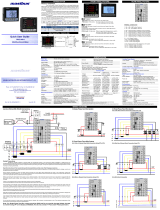
6.2 Common Wiring with RS-485 Connections
Recommended wiring for Aux Supply, Voltage input & Current Input along with RS-485
Connections
Also note correct polarity for Current Input & Phase wise Voltage & Current Input
combination is essential
6.3 Terminal Wiring Details

Model: PM-2160-A
Doc. Ref. no. : m20Aom201
Issue no. 02
User’s Manual Page 18 of 36
6.3.1 Three Phase Four Wire System
a) 4-Wire Wye-3 Element Connection Using 3PTs, 3CTs
b) 4-Wire Wye-3 Element Direct Connection Using 3CTs

Model: PM-2160-A
Doc. Ref. no. : - m20Aom201
Issue no. 02
Page 19 of 36 User’s Manual
c) 4-Wire Direct Connection
6.3.2 Three Phase Three Wire System
a) 3-Wire 2- Element Open Delta Connection Using 2PTs, 2CTs

Model: PM-2160-A
Doc. Ref. no. : m20Aom201
Issue no. 02
User’s Manual Page 20 of 36
b) 3-Wire 2- Element Direct Connection Using 2CTs
6.3.3 Single Phase Two Wire Configuration
Note: -For Single Phase Two Wire, system should be 3P4W and Do not consider Average Voltage,
Average Current & Average PF on the display or MODBUS.
/