16
ModBus Protocol Implementation
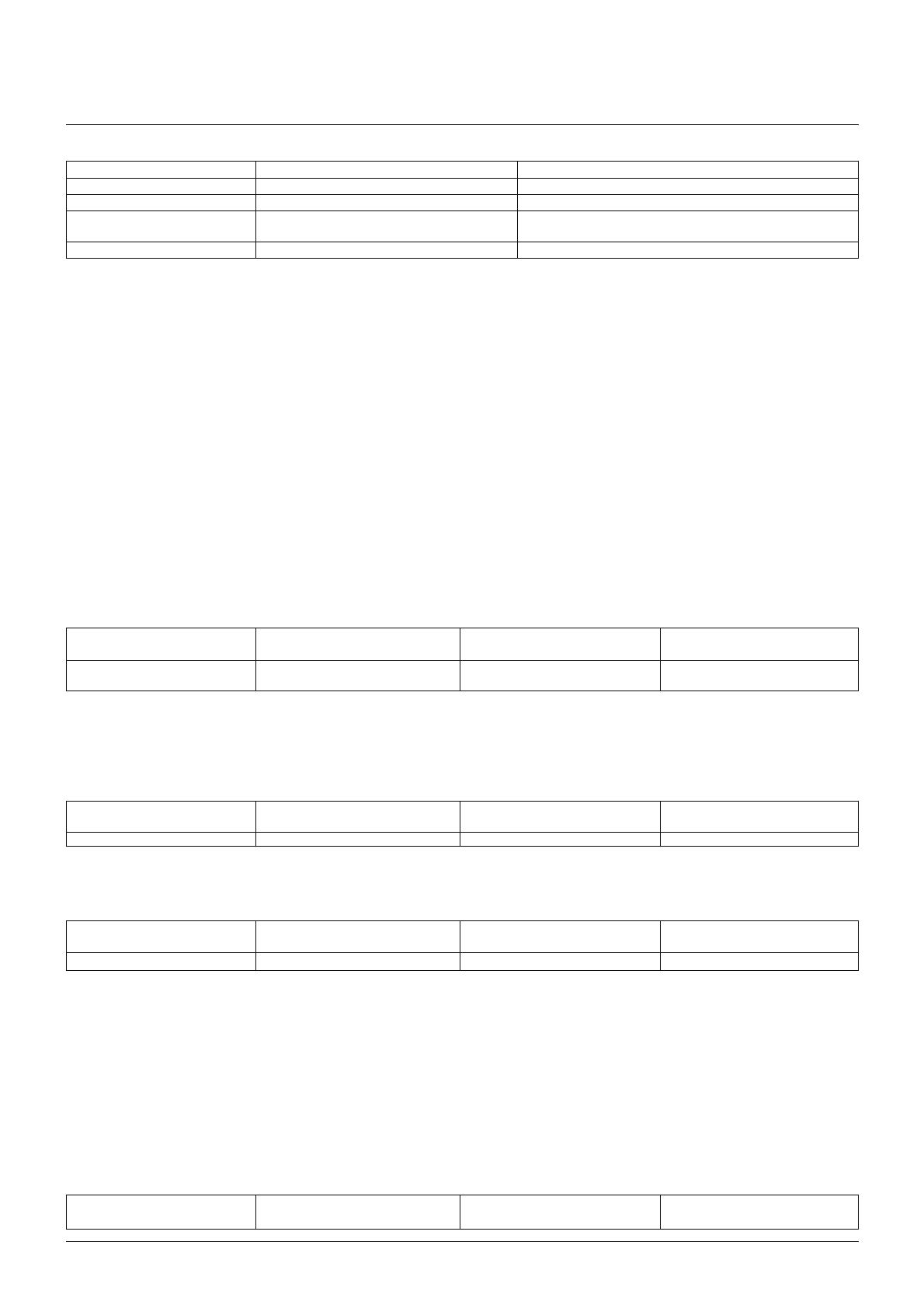
Code MODBUS Protocol name Description
03 Read Holding Registers Read the contents of read/write location (4X references)
04 Read Input Registers Read the contents of read only location (3X references)
08 Diagnostics Only sub-function zero is supported. This returns the data
element of the query unchanged.
15 Pre-set Multiple Registers Set the contents of read/write location (4X references)
3.7 IEEE floating point format
The MODBUS Protocol defines 16 bit “Registers” for the data variables. A 16-bit number would prove too restrictive, for energy parameters for
example, as the maximum range of a 16-bit number is 65535.
However, there are a number of approaches that have been adopted to overcome this restriction. The NMID30-1 Digital meters use two consecutive
registers to represent a floatingpoint number, effectively expanding the range to +/- 1x1037.
The values produced by The NMID30-1 Digital meters can be used directly without any requirement to “scale” the values, for example, the units for the
voltage parameters are volts, the units for the power parameters are watts etc.
What is a floating point Number?
A floating-point number is a number with two parts, a mantissa and an exponent and is written in the form 1.234 x 10⁵. The mantissa (1.234 in this
example) must have the decimal point moved to the right with the number of places determined by the exponent (5 places in this example) i.e. 1.234x
105 = 123400. If the exponent is negative the decimal point is moved to the left.
What is an IEEE 754 format floating-point number?
An IEEE 754 floating point number is the binary equivalent of the decimal floating-point number shown above. The major difference being that the most
significant bit of the mantissa is always arranged to be 1 and is thus not needed in the representation of the number. The process by which the most
significant bit is arranged to be 1 is called normalization, the mantissa is thus referred to as a “normal mantissa”. During normalization the bits in the
mantissa are shifted to the left whilst the exponent is decremented until the most significant bit of the mantissa is one. In the special case where the
number is zero both mantissa and exponent are zero.
The bits in an IEEE 754 format have the following significance:
Data Hi Reg, Data Hi Reg, Data Lo Reg, Data Lo Reg,
Hi Byte. Lo Byte. Hi Byte. Lo Byte.
SEEE EMMM MMMM MMMM
EEEE MMMM MMMM MMMM
Where:
S represents the sign bit where 1 is negative and 0 is positive
E is the 8-bit exponent with an offset of 127 i.e. an exponent of zero is represented by 127, an
exponent of 1 by 128 etc.
M is the 23-bit normal mantissa. The 24th bit is always 1 and, therefore, is not stored.
Using the above format the floating point number 240.5 is represented as 43708000 hex:
Data Hi Reg, Data Hi Reg, Data Lo Reg, Data Lo Reg,
Hi Byte. Lo Byte. Hi Byte. Lo Byte.
43 70 80 00
The following example demonstrates how to convert IEEE 754 floating-point numbers from their hexadecimal form to decimal form. For this example, we will use the value
for 240.5 shown above. Note that the floating-point storage representation is not an intuitive format. To convert this value to decimal, the bits should be separated as
specified in the floating-point number storage format table shown above.
For example:
Data Hi Reg, Data Hi Reg, Data Lo Reg, Data Lo Reg,
Hi Byte. Lo Byte. Hi Byte. Lo Byte.
0100 0011 0111 0000 1000 0000 0000 0000
From this you can determine the following information.
• The sign bit is 0, indicating a positive number.
• The exponent value is 10000110 binary or 134 decimal. Subtracting 127 from 134 leaves 7, which is the actual exponent.
• The mantissa appears as the binary number 11100001000000000000000
There is an implied binary point at the left of the mantissa that is always preceded by a 1. This bit is not stored in the hexadecimal representation of the floating-point number.
Adding 1 and the binary point to the beginning of the mantissa gives the following: 1.11100001000000000000000
Now, we adjust the mantissa for the exponent. A negative exponent moves the binary point to the left. A positive exponent moves the binary point to the right. Because the
exponent is 7, the mantissa is adjusted as follows: 11110000.1000000000000000
Finally, we have a binary floating-point number. Binary bits that are to the left of the binary point represent the power of two corresponding to their position. For example,
11110000 represents (1 x 27) + (1 x 26) + (1x 25) + (1 x 24) + (0 x 23)+ (0 x 22) + (0 x 21)+ (0 x 20) = 240.
Binary bits that are to the right of the binary point also represent a power of 2 corresponding to their position. As the digits are to the right of the binary point the powers are
negative. For example: .100 represents (1 x 2-1) + (0 x 2-2)+ (0 x 2-3) + … which equals 0.5.
Adding these two numbers together and making reference to the sign bit produces the number +240.5.
For each floating point value requested two MODBUS Protocol registers (four bytes) must be requested. The received order and significance of these four bytes for Eastron
Digital meters is shown below:
Data Hi Reg, Data Hi Reg, Data Lo Reg, Data Lo Reg,
Hi Byte. Lo Byte. Hi Byte. Lo Byte
NMID30-1 _ Modbus


