Page is loading ...

Customer Support: [email protected]
MASIBUS AUTOMATION AND INSTRUMENTATION PVT. LTD.
For Sales Service, Call TOLL FREE (India only)
1-800-233-2273
1-800-ADD-CARE
Email: [email protected]
Phone: +91-79-23287275-79; Fax: +91-79-23287281-82
Web: www.masibus.com
Doc. Ref. No. m24/om/102 Issue No: 04
Please read the manual carefully before
Installation/Configuration
Operator’s Manual
VAF-23XX
Volts-Amps-Frequency Indicator
VAF-2310
VAF-2330
SAFETY / WARNING PRECAUTIONS
WARRANTY
Dangerous voltages capable of causing death are sometimes present
in this instrument. Before installation or beginning of any
troubleshooting procedures the power to all equipment must be
switched off and isolated. Units suspected of being faulty must be
disconnected and removed first and brought to a properly equipped
workshop for testing and repair. Component replacement and interval
adjustments must be made by a company person only.
Safety precautions
· Before wiring, verify the label for correct model number and options.
· Wiring must be carried out by personnel, who have basic electrical
knowledge and practical experience.
· All wiring must confirm to appropriate standards of good practice and local
codes and regulations. Wiring must be suitable for voltage, current, and
temperature rating of the system.
· Beware not to over-tighten the terminal screws.
· Verify that the ratings of the output devices and the inputs as specified in this
manual are not exceeded.
· Upon receipt of the shipment remove the unit from the carton and inspect
the unit for shipping damage. If any damage due to transit, report and claim
with the carrier. Write down the model number and serial number for future
reference when corresponding with our Customer Support Division.
· Do not use this instrument in areas such as excessive shock, vibration, dirt,
moisture, corrosive gases or rain. The ambient temperature of the areas
should not exceed the maximum rating specified.
Warning precautions
Warranty does not apply to defects resulting from action of the user such as
misuse, improper wiring, operation outside of specification, improper
maintenance or repair, or unauthorized modification.
Masibus is not liable for special, indirect or consequential damages or for
loss of profit or for expenses sustained as a result of a device malfunction,
incorrect application or adjustment
Masibus' total liability is limited to repair or replacement of the product. The
warranty set forth above is inclusive and no other warranty, whether written
or oral, is expressed or implied
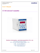
Panel Cutout Diagram
PI-Series (PI-VAF3, PI-VAF1, PI-V1, PI-V3, PI-A1, PI-A3, PI-F) power indicators
can be used to monitor Voltage, Current, Frequency and RPM of three phase and
single phase two wire electrical system.
To get the best out of your investment, we suggest that you take a few moments to
review this manual. Before use, please program the TYPE (measurement
system configuration), PT Ratio and CT Ratio though the front panel keys.
Otherwise, it will read your system incorrectly.
Current Input
3
Note: -
1-Phase Voltage & Current are available in Single Line Selection Only
Frequency is available only on 1-phase & Single Line Selection Only
CT input is applicable while selecting A or VAF as a display
Front Bezel Diagram Side View
MECHANICAL GUIDELINE
Kilo
Hz
A
masibus
PROG
ENTR
VL-N
2330
VL-L
L3-1
L2-3
L1-2
100.00 mm
100.00 mm
100.00 mm
90.00 mm
55.00 mm
50.00 mm
92.00 mm
92.00 mm
Panel Cut Out
Description Quantity
Sr. No.
Panel Mount Clamps 02
2User Manual 01
1
List Of Accessories
PRODUCT OVERVIEW
INTRODUCTION
Product Ordering Code
23 xx x x x
1
N
5
0
1
2
3
1
3
10 Single Line 1- Phase F (Freq.)
V(Volt)
A(Amp)
1 Amps
None
5 Amps
VAF
Three Line 3- Phase
30
Display Phase ParameterModel
2
1
1
2
3
SPECIFICATION
Accuracy
Voltage ± 0.5% of FS +/-1 Digit
(20 -120% of Nominal Value)
Current
± 0.3% of FS +/-1 Digit
(1-120% of Nominal Value)
Frequency
± 0.5% of Reading (>40V Input)
Environmental
Working temperature 0 to 55ºC
Storage temperature -10 to 70ºC
Relative humidity 30-95% non-condensing
Isolation (Withstanding voltage)
Between Field input[voltage & Current] terminals and
Auxiliary power supply terminal
At least 1500 V AC for 1 minute
Insulation resistance: 20MΩ or more @ 500 V DC between field
input[voltage & Current] terminals and Aux. power supply terminals
Physical
Mounting Type Panel mount
Size (mm) 100 x 100 x 55 mm
Front Bezel (mm) 100 x 100 mm
Panel Cutout (mm) 92 x 92 mm
Depth behind panel 50 mm
Weight 250 gms
Enclosure Protection Rating Ip20
Material ABS
Accessory 2 Panel mount clamps
Range
Range
Power Supply
Burden
0 to 100 poles [configurable]
MAX. 999999 Hours 59 Minutes
Resulution: 1 Minute
Less than 3VA
90-270VAC, 50/60Hz or 100-300VDC
RPM
ON Hour
Run Hour
Number of poles can be configured
depending upon Application requirements
Total Hours for unit ON condition
Total Hours for unit with load condition
Auxiliary Power Supply
Measurement Parameters
Voltage
Current
RPM
All Phase Current , Max.Value
Calculation Based RPM
(Available in 3 line, 3 Phase model)
(Available in 3 line, 3 Phase model)
L1-N,L2-N,L3-N ,L1-L2,L2-L3,L3-L1,Max.Value
Frequency
Hours
System Frequency
ON Hour, Run Hour
Input
Voltage
Measurement Method
Accuracy
Measurement Method
True RMS
Class 1.0
True RMS
Burden
Burden
PT Ratio
CT Ratio
0.5VA per phase
0 to 550V L-N
0.25VA per phase
1 to 9999 Programmable
1 to 9999 Programmable
Wire guage
Wire guage
Overload
Overload
Frequency 45 to 65Hz
Current
Secondary Current 1A/5A(Factory Selectable)
16AWG
16AWG
1.2 x Nominal Voltage (Continuous)
1.2 x Nominal Voltage (Continuous)
Display 0.56”[14mm] height seven segment,
RED colour
4 Digit, Three line Display(2330)
4 Digit, Single line Display(2310)
System Type
Three Phase Four Wire (3P4W)
Three Phase Three Wire (3P3W)
Single Phase Two Wire (1P2W)
Direct Voltage
ISTALLATION GUIDELINE
3. Single Phase Two Wire Wiring Configuration
2. Three Phase Three Wire Wiring Configuration
Terminal Wiring Details
1. Three Phase Four Wire Wiring Configuration
TERMINAL CONNECTION
1- L = Phase of auxiliary AC supply.
2- N = Neutral of auxiliary AC supply.
7- VR = R phase voltage connection.
8- VY = Y phase voltage connection.
9- VB = B phase voltage connection.
10- VN = Neutral point for three phase four wire system.
15- IR+ = Input terminal for R phase current connection.
16- IR- = Output terminal for R phase current connection.
17- IY+ = Input terminal for Y phase current connection.
18- IY- = Output terminal for Y phase current connection.
19- IB+ = Input terminal for B phase current connection.
20- IB- = Output terminal for B phase current connection.
L1
L3
L2
N
LOAD
SIDE
masibus
Aux. Supply
90-270VAC
100-300VDC
1 2 345678 9 10
LN VR VY VB N
11 12 13 14 15 16 17 18 19 20
IY+IR- IY- IB+ IB-IR+
N
B
Y
+
+
+
-
-
-
R
45 - 65 Hz
V
A
Ord. Code
Serial No.
www.masibus.com
So. No.
Voltage
Current
Freq.
3Ø
2330
1Ø
2310 V A F
L
NLOAD
SIDE
masibus
Aux. Supply
90-270VAC
100-300VDC
1 2 345678 9 10
LN VR VY VB N
11 12 13 14 15 16 17 18 19 20
IY+IR- IY- IB+ IB-IR+
N
B
Y
+
+
+
-
-
-
R
45 - 65 Hz
V
A
Ord. Code
Serial No.
www.masibus.com
So. No.
Voltage
Current
Freq.
3Ø
2330
1Ø
2310 V A F
L1
L3
L2 LOAD
SIDE
masibus
Aux. Supply
90-270VAC
100-300VDC
1 2 345678 9 10
LN VR VY VB N
11 12 13 14 15 16 17 18 19 20
IY+IR- IY- IB+ IB-IR+
N
B
Y
+
+
+
-
-
-
R
45 - 65 Hz
V
A
Ord. Code
Serial No.
www.masibus.com
So. No.
Voltage
Current
Freq.
3Ø
2330
1Ø
2310 V A F

FRONT & REAR PANEL PICTURE
Front Panel Picture
Kilo
Hz
A
masibus
PROG
ENTR
VL-N
2330
VL-L
L3
L2
L1
2404
2406
2403
LED INDICATION
I/P VOLT TYPE
AUTO SCROLLING
FEATURE
3 PHASE
BRIGHT LED
DISPLAY
PROGRAM/ENTER KEY
PASSWORD PROTECTED
CONFIGURABLE PARAMETERS
• PTR
• CTR
• TYPE (3P4W/3P3W)
• PASSWORD
UP KEY DOWN/SHIFT KEY
PROG
ENTR
PROG/ENTR
RUN mode:
· If Key Remains pressed for 4 Second it will enter into PROG mode(View
mode)
PROG mode:
On key press
· If in view mode goes into edit mode.
· If in edit mode goes into view mode.
DECREMENT/SHIFT KEY
PROG mode:
· Shift Digit in edit mode.
· When in view mode this key press is used to exit from PROG mode to
RUN mode.
RUN mode:
· Key press is used to display next parameter.
Front Panel Picture
Rear Panel Picture
VL-N
VL-L
A
A
Hz
Kilo
Kilo
INCREMENT KEY
PGM mode:
· Increment value in edit mode
· Display next configuration parameter in view mode
RUN mode:
· Key press is used to display next parameter.
Indicates Phase to Neutral voltage
Indicates Phase to Phase voltage
Indicates Current
Indicates Frequency
Indicates Unit
When Unit LED and VL-N / Vboth are ON its Idicates Voltage in KV
L-L
range
Kilo
When Unit LED and
VL-N
both are ON its Idicates Voltage in KA
range
VL-N
VL-L
A
A
A
Hz
Kilo
Kilo
INCREMENT KEY
PGM mode:
· Increment value in edit mode
· Display next configuration parameter in view mode
RUN mode:
· Key press is used to display next parameter.
Indicates Phase to Neutral voltage
Indicates Phase to Phase voltage
Indicates Current
Indicates Frequency
Indicates Unit
When Unit LED and VL-N / Vboth are ON its Idicates Voltage in KV
L-L
range
Kilo
When Unit LED and
In Favourite page/Manual Scroll, indication LED for each page will blink
continuously
In Auto Scroll, indication LED for each pages will remain ON.
VL-N
both are ON its Idicates Voltage in KA
range
CONFIGURATION PARAMETER DETAILS (3-line Display)
Ptr-
Ctr-
type
RPM pole
pswd
Hour rst
High rst
Scrl
Password Selection Range
Reset ON & LOAD Hour Value
Reset High Value
Set Page Scroll in Auto or manual (Favourite page store) mode
1
1
0
1
-
-
-
-
-
-
1
Auto
9999
100 0
9999
9999
1
1
P rimary to Secondary Voltage Ratio
Description Min. Value Max. Value Default Value
Parameters
P rimary to Secondary Current Ratio
3 P4W 3 P4W wire connection (Display P-N & P-P voltage)
3 P3W wire connection (Display only P-P voltage)
3 P3W
N umber of pole
RUN MODEMODEL CONFIGURATION MODE
V3
A3
Voltage L-N, Voltage L-L
Current
Ptr, type, pswd,High rst, Scrl
Ctr, type, pswd,High rst, Scrl
Available pages in Other Models of 2330, 3 Line Display
VAF1
Vr, Ir, F Ptr, Ctr, pswd,High rst, Scrl
240.0
240.0
240.0
240.0
240.0
240.0
240.0
High
5.000
241.0
415.9
5.006
241.2
416.0
5.010
240.8
416.1
5.004
50.00
RUN MODE
VIEW
MODE
EDIT
MODE
240.0 EnTr
240.0 PSWd
240.0
415.8
415.8
415.8
5.000
5.000
5.000
rpm-
Hour
Hour
1000
1023
52.45
1015
25.40
50.00
0001
CONFIGURATION MODE
Ptr-
0001
Ptr-
0001
RUN
MODE
PROG
ENTR
PROG
ENTR
PROG
ENTR
PROG
ENTR
PROG
ENTR
PROG
ENTR
PROG
ENTR
PROG
ENTR
PROG
ENTR
PROG
ENTR
PROG
ENTR
PROG
ENTR
PROG
ENTR
PROG
ENTR
PROG
ENTR
PROG
ENTR
PROG
ENTR
PROG
ENTR
PROG
ENTR
PROG
ENTR
SHIFT
INC
SHIFT
INC
SHIFT
INC
SHIFT
INC
SHIFT
INC
SHIFT
INC
Ptr-
0001
pswd
0001
Ptr-
0001
pswd
0001
Ptr-
0001
pswd
0001
Ptr-
0001
pswd
0001
Ptr-
0001
pswd
0001
Ptr-
0001
pswd
0001
RUN
MODE
Ptr-
Ptr-
Ptr-
0001
0001
0001
pswd
pswd
pswd
0001
0001
0001
Ptr-
Ptr-
Ptr-
0001
0001
0001
pswd
pswd
pswd
0001
0001
0001
Ptr-
0001
Ctr-
0001
Ptr-
0001
Ctr-
0001
RUN
MODE
Ptr-
0001
type
3p4w
Ptr-
0001
type
3p4w
RUN
MODE
Ptr-
0001
rpm-
pole
0001
Ptr-
0001
rpm-
pole
Ptr-
Ptr-
Ptr-
0001
0001
0001
0001
0001
0001
RUN
MODE
RUN
MODE
RUN
MODE
pswd
sCrl
Hour
pswd
SCRL
Hour
0001
auto
rst.
done
0001
auto
rst.
0001
240.0
240.0
240.0
{{
Voltage L-NVoltage L-L
Current
Frequency
RPMON HourRun Hour
1-phase
VAF
Press
for
4 sec.
*Display
for 1 sec
*Display for
4 sec.
Ptr-
0001
pswd
0001
Ptr-
0001
pswd
0001
Ptr-
0001 0001
RUN
MODE
HighHigh
rst.
done
rst.
CONFIGURATION PARAMETER DETAILS FOR 2310 (1-line Display)
RUN MODE
VIEW
MODE EDIT
MODE
PSWd
0001
415.8
5.000
415.8
50.00
CONFIGURATION MODE
Ptr- 0001 0001
0001
SHIFT
INC
INC
INC
INC
INC
PROG
PROG
PROG
PROG PROG
PROG PROG
PROG
PROG
PROG
PROG
PROG
PROGPROG
ENTR
ENTR
ENTR
ENTR ENTR
ENTR ENTR
ENTR
ENTR
ENTR
ENTR
ENTR
ENTRENTR
PROGPROG
ENTRENTR
SHIFT
SHIFT
SHIFT
SHIFT
PROGPROGPROG
Ptr-pswdPtr-
Ctr- 000100010001
0001
000100010001
3p4w 000100010001
3p4w
Ptr-
Ptr-
pswd
pswd
Ptr-
Ptr-
pswd
SCRL
type
0001
0001
0001
0001
0001
0001
0001
Auto
0001
0001
0001
0001
0001
0001
0001
auto
RUN
MODE
240.0
415.8
240.0
5.000
240.0
5.000
Vr L-N
Vy L-N
Ir
Vb L-N
Vry L-L
Vrb L-L
Vyb L-L
Iy
Ib
Freq
Available pages in Other Models of 2310, 1 Line Display
RUN MODE CONFIGURATION MODE
V3
A3
F
V1
A1
VAF1
Vr L-N, Vy L-N, Vb L-N,
Ir, Iy, Ib
F
Vr L-N
Ir
Vr, Ir, F
Vry L-L, Vyb L-L, Vbr L-L Ptr, type, pswd,Scrl
Ptr, pswd,Scrl
Ctr, pswd,Scrl
Ctr, type, pswd,Scrl
Ptr, Ctr, pswd,Scrl
-
PROG
ENTR
masibus
Aux. Supply
90-270VAC
100-300VDC
1 2 345678 9 10
LN VR VY VB N
11 12 13 14 15 16 17 18 19 20
IY+IR- IY- IB+ IB-IR+
N
B
Y
+
+
+
-
-
-
R
45 - 65 Hz
V
A
Ord. Code
Serial No.
www.masibus.com
So. No.
Voltage
Current
Freq.
3Ø
2330
1Ø
2310 V A F
/