Smappee MID 100A Series User manual

Type
User manual

Smappee MID 100A Series smart meters provide real-time monitoring of your electrical system, displaying voltage, current, power, energy consumption, and more. Track energy usage, detect power outages, and optimize energy efficiency. Easily set up and manage multiple devices via the intuitive interface or connect to your home automation system for remote monitoring and control.

Smappee MID 100A Series smart meters provide real-time monitoring of your electrical system, displaying voltage, current, power, energy consumption, and more. Track energy usage, detect power outages, and optimize energy efficiency. Easily set up and manage multiple devices via the intuitive interface or connect to your home automation system for remote monitoring and control.

MID 100A SERIES
DIN rail smart meters for single and
three phase electrical systems
User manual v1.0
1
Introduction
This document provides operating, maintenance and
installation instructions. These units measure and display
the characteristics of single phase two wires (1p2w), three
phase three wires (3p3w) and three phase four wires (3p4w)
networks. The measuring parameters include voltage (V),
frequency (Hz), current (A), power (kW/kVa/kVar), import,
export and total Energy (kWh/kVarh). The units can also
measure Maximum demand current and power, this is
measured over preset periods of up to 60 minutes.
These units are max 100A direction operated and do
not need to connect with external current transformers
(CT).Built-in pulse, RS485 Modbus RTU/Mbus outputs.
Configuration is password protected.
1.1
Unit characteristics
The Smappee MID 100A SERIES meters have seven models,
1 is used:
Model Measurement
Output Tariff
i1-EN3-1
kWh/kVarh, kW/kVar, kVA, P, F,
PF, dmd, V, A, THD…
pulse/Modbus
1.2
RS485 serial Modbus RTU
RS485 serial port with Modbus RTU protocol to provide a
means of remotely monitoring and controlling the Unit. Set-
up screens are provided for setting up the RS485 port.
1.3
Mbus
This uses an MBus port with EN13757-3 protocol to provide
a means of remotely monitoring and controlling the Unit.
Set-up screens are provided for setting up the MBus port.
1.4
Pulse output
Two pulse outputs that pulse measured active and reactive
energy. The constant of pulse output 2 for active energy is
400imp/kWh (unconfigurable), its width is fixed at 100ms.
The default constant of configurable pulse output 1 is
400imp/kWh, default pulse width is 100ms. The configurable
pulse output 1 can be set from the set-up menu.
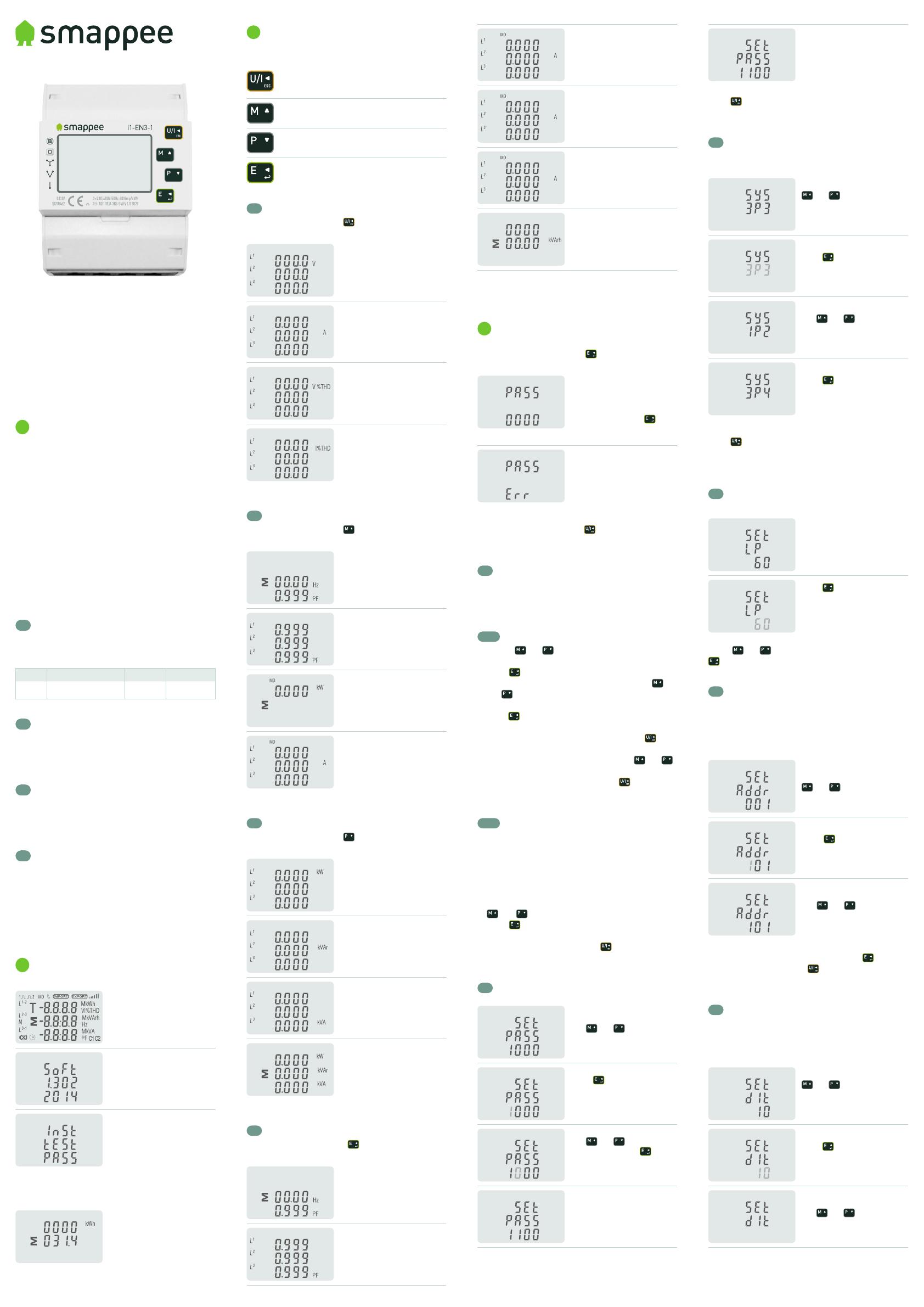
2
Start-up screens
The first screen lights up all
display segments and can be
used as a display check.
Software version information.
The interface performs a self-
test and indicates the result if
the test passes.
After a short delay, the screen will display active energy
interface as follows:
Total active energy in kWh.
3
Measurements
The buttons operate as follows:
Selects the Voltage and Current display screens.
In Set-up mode, this is the “Left” or “Back”
button.
Select the Frequency and Power factor display
screens. In Set-up mode, this is the “Up” button.
Select the Power display screens. In Set-up
mode, this is the “Down” button.
Select the Energy display screens. In Set-up
mode, this is the “Enter” or “Right”.
3.1
Voltage and current
Each successive press of the button selects a new
parameter:
Phase to neutral voltages.
Current on each phase.
Phase to neutral voltage
THD% of 2nd to 19th.
Each phase Current THD% of
2nd to 19th.
3.2
Frequency, power factor and demand
Each successive press of the button selects a new
range:
Frequency and Power Factor
(total).
Power Factor of each phase.
Maximum Power Demand.
Maximum Current Demand.
3.3
Power
Each successive press of the button selects a new
range:
Instantaneous Active Power
in kW.
Instantaneous Reactive Power
in kVar.
Instantaneous Volt-Amps in
KVA.
Total kW, kVarh, kVA.
3.4
Energy measurements
Each successive press of the button selects a new
range:
Import active energy in kWh.
Export active energy in kWh.
Total active energy in kWh.
Import reactive energy.
Export reactive energy.
Total reactive energy.
*The date and time can only be set via RS485
communication.
4
Set-up
To enter set-up mode, press the button for 3 seconds,
until the password screen appears.
Setting up is password-
protected so you must
enter the correct password
(default 1000) before
processing. Press the
button for 3 seconds to
confirm.
If an incorrect password is
entered, the display will show:
PASS Err
To exit setting-up mode, press repeatedly until the
measurement screen is restored.
4.1
Set-up entry methods
Some menu items, such as password, require a four-
digits number entry while others, such as supply system,
require selection from a number of menu options.
4.1.1
Menu option selection
1. Use the and buttons to scroll through the
different options of the set-up menu.
2. Press to confirm your selection.
3. If an item flashes, then it can be adjusted by the
and buttons.
4. Having selected an option from the current layer,
press to confirm your selection. The SET indicator
will appear.
5. Having completed a parameter setting, press to
return to a higher menu level. The SET indicator will
be removed and you will be able to use the and
buttons for further menu selection.
6. On completion of all setting-up, press repeatedly
until the measurement screen is restored.
4.1.2
Number entry procedure
When setting up the unit, some screens require the
entering of a number. In particular, on entry to the setting
up section, a password must be entered. Digits are
set individually, from left to right. The procedure is as
follows:
1. The current digit to be set flashes and is set using the
and buttons.
2. Press to confirm each digit setting. The SET
indicator appears after the last digit has been set.
3. After setting the last digit, press to exit the number
setting routine. The SET indicator will be removed.
4.2
Change password
Use and to choose the
change password option.
Press to enter the change
password routine. The new
password screen will appear
with the first digit flashing.
Use and to set the
first digit and press to
confirm your selection. The
next digit will flash.
Repeat the procedure for the
remaining three digits.
After setting the last digit,
SET will show.
Press to exit the number setting routine and return to
the Set-up menu. SET will be removed.
4.3
Supply system
*The unit has a default setting of 3Phase 4wire (3P4).
Use this section to set the type of electrical system.
From the set-up menu, use
and to select the
system option. The screen will
show the currently selected
power supply.
Press to enter the
selection routine. The current
selection will flash.
Use and to select the
required system option:
1P2 (W), 3P3 (W), 3P4 (W).
Press to confirm the
selection. SET indicator will
appear.
Press to exit the system selection routine and return
to the menu. SET will disappear and you will be returned
to the main set-up Menu.
4.4
Backlit set-up
Backlit lasting time is settable, default is 60minutes.
If it’s setted as 5, the backlit
will be off in 5 minutes if there
is no more further operation.
Press to enter the
selection routine. The current
time interval will flash.
The options are:
0 (always on) /5/10/30/60/120
Press and to select the time interval. Then press
to confirm the set-up.
4.5
Communication
There is RS485/Mbus port can be used for
communication Modbus RTU protocol. For Modbus RTU,
parameters are selected from front panel.
The first screen below shows a range from 001 to 247.
From the set-up menu, use
and to select the
address ID.
Press to enter the
selection routine. The
current setting will flash.
Use and to choose
Modbus address (001 to 247).
On completion of the entry procedure, press to
confirm the setting and press to return to the main
set-up menu.
4.6
Demand integration time (DIT)
This sets the period in minutes over which the current
and power readings are integrated for maximum demand
measurement. The options are: 0, 5, 8, 10, 15, 20, 30, 60
minutes.
From the set-up menu, use
and to select the
DIT option. The screen will
show the currently selected
integration time.
Press to enter the
selection routine. The current
time interval will flash.
Use and to select the
time required.
Press to confirm the
selection. SET indicator will
appear.
Press to exit the DIT selection routine and return to the
menu.
4.7
Demand integration time (DIT)
This sets the period in minutes over which the current
and power readings are integrated for maximum demand
measurement. The options are: 0, 5, 8, 10, 15, 20, 30, 60
minutes.
From the set-up menu, use
and to select the
DIT option. The screen will
show the currently selected
integration time.
Press to enter the
selection routine. The current
time interval will flash.
Use and to select the
time required.
Press to confirm the
selection. SET indicator will
appear.
Press to exit the DIT selection routine and return to the
menu.
4.8
CLR
The meter provides a function to reset the maximum
demand value of current and power.
From the set-up menu, use
and to select the
reset option.
Press to enter the
selection routine. The MD
will flash.
Press to confirm the setting and press to return to
the main set-up menu.
4.9
Pulse output
This option allows you to configure the pulse output 1. The
output can be set to provide a pulse for a defined amount
of energy active or reactive. Use this section to set up the
pulse output for:
Total kWh/Total kVarh
Import kWh/Export kWh
Import KVarh/Export KVarh
From the set-up menu, use
and to select the Pulse
output option.
Press to enter the
selection routine. The unit
symbol will flash.
Use and to choose
kWh or kVarh.
On completion of the entry procedure, press to
confirm the setting and press to return to the main set
up menu.
4.9.1
Pulse rate
Use this to set the energy represented by each pulse.
Rate can be set to 1 pulse per dFt/0.01/0.1/1/10/100 kWh/
kVarh. The first screen below shows 1 pulse = 10kWh/
kVarh.
From the set-up menu, use
and to select the
Pulse rate option.
Press to enter the
selection routine. The
current setting will flash.
When it’s dFt (default), it
means 2.5Wh/Varh.
Use and to choose pulse rate. On completion of
the entry procedure, press to confirm the setting and
press to return to the main set-up menu.
4.9.2
Pulse duration
The pulse width can be selected as 200ms (non-MID
version meters only), 100ms (default) or 60ms.
The first screen below shows default pulse width.
From the set-up menu, use
and to select the
Pulse width option.
Press to enter the
selection routine. The
current setting will flash.
Use and to choose pulse width. On completion of
the entry procedure, press to confirm the setting and
press to return to the main set-up menu.
5
Specifications
5.1
Measured parameters
The unit can monitor and display the following
parameters of a single phase two wire (1p2w), three
phase three wire (3p3w) or three phase four wire (3p4w)
system.
5.1.1
Voltage and current
Phase to neutral voltages 176 to 276V a.c. (not for 3p3w
supplies).
Voltages between phases 304 to 480V a.c. (3p supplies
only).
Percentage total voltage harmonic distortion (THD%)
for each phase to N ( not for 3p3w supplies).
Percentage voltage TH D% between phases (three
phase supplies only).
Current THD% for each phase.
5.1.2
Power factor, frequency and max
demand
Frequency in Hz
Instantaneous power:
Power 0 to 99999 W
Reactive power 0 to 99999 Var
Volt-amps Oto 99999 VA
Maximum demanded power since last Demand reset
Power factor
Maximum neutral demand current, since the last
Demand reset (for three phase supplies only)
5.1.3
Energy measurements
Import active energy:
Export reactive energy:
Import active energy:
Export reactive energy:
Total active energy:
Total reactive energy:
0 to 999999.99 kWh
0 to 999999.99 kVarh
0 to 999999.99 kWh
0 to 999999.99 kVarh
0 to 999999. 99 kWh
0 to 999999.99 kVarh
5.2
Measured inputs
Voltage inputs through 4-way fixed connector with 25mm2
stranded wire capacity, single phase two wire (1 p2w),
three phase three wire (3p3w) or three phase four wire
(3p4w) unbalanced. Line frequency measured from L1
voltage or L3 voltage.
5.3
Interfaces for external monitoring
Three interfaces are provided:
RS485/Mbus communication channel that can be
programmed via protocol remotely. (not for SDM630-
Pulse V2)
Pulse output (pulse1) indicating real-time measured
energy (configurable)
Pulse output (pulse2) 400imp/kWh (not configurable)
The Modbus/Mbus configuration (baud rate, etc) and
the pulse relay output assignments (kW/kVarh, import/
export, etc) are configured through the set-up screens.
5.3.1
Pulse output
The pulse output can be set to generate pulses to
represent
kWh or kVarh. Rate can be set to generate 1 pulse per:
dFt
0.01
0.1
1
10
100
= 2.5 Wh/Varh (default)
= 10 Wh/Varh
= 100 Wh/Varh
= 1 kWh/kVarh
= 10 kWh/kVarh
= 1 00 kWh/kVarh
Pulse width: 200/100/60 ms
Pulse output 2 is non-configurable. It is fixed up with
active kWh. Its constant is 400imp/kWh.
5.3.2
RS485/Mbus output for communication
For Modbus RTU, the following RS485 communication
parameters can be configured from the set-up menu:
Baud rate: 2400, 4800, 9600, 19200, 38400
Parity: none, odd, even
Stop bits: 1 or 2
RS485 network address (nnn): 001 to 247
If the Modbus/Mbus protocol document is required,
please contact us.
5.4
Accuracy
Voltage:
Current:
Frequency:
Power factor:
Active power (W):
Reactive power (VAr):
Apparent power (VA):
Active energy (Wh):
Reactive energy (VARh):
Response time to step
input:
0.5 % of range maximum
0.5 % of nominal
0.2 % of mid-frequency
1 % of unity (0.01)
± 1 % of range maximum
Class 1 IEC 62053-21,
Class B EN504 70-3
± 1 % of range maximum
1s, typical, to >99% of final
reading, at 50 Hz
5.5
Reference conditions of influence
quantities
Influence Quantities are variables that affect
measurement errors to a minor degree. Accuracy
is verified under nominal value (within the specified
tolerance) of these conditions.
Ambient temperature:
Input frequency:
Input waveform:
Magnetic field of ext.
origin:
23°c ± 2°c
50 Hz (MID),
50 or 60Hz ±2% (non-MID)
Sinusoidal (distortion factor
< 0.005)
Terrestrial flux
5.6
Environment
Operating temperature:
Storage temperature:
Relative humidity:
Altitude:
Warm up time:
Vibration:
Shock:
-25°C to +55°C*
-40°C to +7C*
0 to 95%, non-condensing
Up to 2000m
1 minute
10Hz to 50Hz, IEC 60068-2-6, 2g
30g in 3 planes
*Maximum operating and storage temperatures are in
the context of typical daily and seasonal variation.
5.7
Mechanics
DIN rail dimensions:
Mounting:
Sealing:
Material:
72×100mm (W×H) per DIN 43880
DIN rail (DIN 43880)
IP51 (indoor)
Self-extinguishing Ul94 V-0
5.8
Reference conditions of influence
quantities
We, Smappee n.v., Declare under our sole responsibility
as the manufacturer that the poly phase multifunction
electrical meter “SMAPPEE MID 100A series” correspond
to the production model described in the EU-type
examination certificate and to the requirements of the
Directive 2014/32/EU EU type examination certificate
number 0120/SGS0462.
Identification number of the NB0120.
6
Dimensions
7
Wiring diagram
Interface for external monitoring:
7.1
Single phase two wires (1P2)
U/I
ESC
M
P
E
7.2
Three phase three wires (3P3)
U/I
ESC
M
P
E
7.3
Three phase four wires (3P4)
U/I
ESC
M
P
E
Safety warnings
Important Safety lnformation is contained in the
Maintenance section. Familiarize yourself with this
information before attempting installation or other
procedures.
Symbols used in this document:
Risk of Danger: These instructions contain
important safety information. Read them before
starting installation or servicing of the equipment.
Caution: Risk of Electric Shock.
Evolis 104, 8530 Harelbeke, Belgium
info@smappee.com
www.smappee.com
  • Page 1 1
  • Page 2 2

Smappee MID 100A Series User manual

Type
User manual

Smappee MID 100A Series smart meters provide real-time monitoring of your electrical system, displaying voltage, current, power, energy consumption, and more. Track energy usage, detect power outages, and optimize energy efficiency. Easily set up and manage multiple devices via the intuitive interface or connect to your home automation system for remote monitoring and control.

Ask a question and I''ll find the answer in the document

Finding information in a document is now easier with AI