Veris T-VER-H970-200 Connection Instructions
- Type
- Connection Instructions

Veris DC Current Transducer (CT) Connection Instructions
For use with HOBO
®
H22, U12, U30, and UX120-006M data loggers and HOBO data nodes
© 2007–2013 Onset Computer Corporation. All rights reserved. Onset, HOBO, and HOBOware are registered trademarks and FlexSmart is a trademark of Onset
Computer Corporation. Other products and brand names may be trademarks or registered trademarks of their respective owners.
11464-G MAN-VERIS-CT
Applies to this Veris CT:
Onset Part No. Current Range Output Veris Part No.
T-VER-H970-200 0-200 Amps DC 4-20mA (or 0-5VDC) representing 0 to 50/100/200 Amps DC H970HCA
DANGER!—HIGH VOLTAGE HAZARD
Installing CT in an energized electrical enclosure or on any energized conductor can result in severe injury or death. This CT is for
installation by qualified personnel only. To avoid electrical shock, do not perform any installation or servicing of this CT unless you
are qualified to do so. Disconnect and lock-out all power sources during installation and servicing. Please read transducer user’s
manual for instructions and use.
This document provides instructions on connecting the Veris CT listed above to each of the
following:
• FlexSmart
™
Analog Module used with HOBO H22 series data loggers
• Analog Sensor Port used with HOBO U30 series data loggers
• 4-20mA cable or voltage adapter used with the U12 and UX120-006M data loggers and
ZW series data nodes
It also lists configuration values used by HOBOware
®
Pro software to configure the logger for CT.
Required:
• Veris CT listed above
• HOBO H22, U12, U30, or UX120-006M data logger, or HOBO ZW data node
• FlexSmart Analog Module, Onset Part No: S-FS-CVIA (for H22 series); Analog Sensor Port option (for U30 series);
4-20mA cable, Onset Part No. CABLE-4-20mA or voltage adapter, Onset Part No. CABLE-ADAP5 (for U12,
UX120-006M, or ZW series)
• HOBOware Pro Software, version 2.2.1 or higher (2.4.0 or higher for U30 series; 3.0 or higher for ZW series; 3.6 or
higher for UX120-006M)
• Customer-supplied lengths of hook-up wire
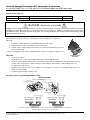
Connecting the CT to the Analog Module or Port:
Shld
S1+
S1-
Exc+
Exc-
S2+
S2-
4-20mA
0-5VDC
Gnd (-)
Power (+)
FlexSmart Analog Module
DC Current Transducer
HOBO H22 Series Data Logger
S-FS-CVIA
FlexSmart Analog Module
DC Current Transducer
DC
LOAD
*The applicable output terminal from the CT is shown connected to the channel 2 input terminal (S2+) on the FlexSmart Analog Module.
If available, the channel 1 input terminal (S1+) can be used instead.
Shld
S1+
S1-
Exc+
Exc-
S2+
S2-
FlexSmart Analog Module
4-20mA
0-5VDC
Gnd (-)
Power (+)
for 4-20mA Output* for 0-5VDC Output*
DC Current Transducer
All wiring
customer-supplied
H22 Connection
Veris DC Current
Transducer
Distributed by MicroDAQ.com, Ltd. www.MicroDAQ.com (603) 746-5524

Veris DC Current Transducer (CT) Connection Instructions
Page 2 of 3
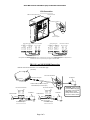
Shield
Ch1 Signal
Ch1 Return
Exc Out
Analog Sensor Port
Shield
Ch2 Signal
Ch2 Return
Ext Return
for 4-20mA Output*
4-20mA
0-5VDC
Gnd (-)
Power (+)
for 0-5VDC Output*
Shield
Ch1 Signal
Ch1 Return
Exc Out
Shield
Ch2 Signal
Ch2 Return
Ext Return
4-20mA
0-5VDC
Gnd (-)
Power (+)
DC Current Transducer
Analog Sensor Port
DC Current Transducer
DC
LOAD
All wiring
customer-supplied
*The applicable output terminal from the CT is shown connected to the channel 2 input terminal (Ch2 Signal) on the Analog Sensor Port.
If available, the channel 1 input terminal (Ch1 Signal) can be used instead.
Analog Sensor Port
DC Current Transducer
HOBO U30 Series Data Logger
U30 Connection
ZW, U12, and UX120-006M Connection
Connect to analog port
CABLE-4-20MA (for 4-20mA output) or
CABLE-ADAP5 (for 0-5VDC output)
for 4-20mA Output
4-20mA
0-5VDC
Gnd (-)
Power (+)
for 0-5VDC Output
4-20mA
0-5VDC
Gnd (-)
Power (+)
DC Current Transducer DC Current Transducer
HOBO ZW Series Wireless Data Node or U12 Series Data Logger
(ZW shown)
DC
LOAD
DC Current Transducer
White (+)
(Red wire not used)
Yellow (+)
Blue (-)
AC-SENS-1*
(+)
(-) Black (-)
CABLE-4-20MA CABLE-ADAP5
AC-SENS-1*
(+)
(-)
AC-SENS-1*
Use appropriate termination
*CAUTION: Polarity is very
important! Before plugging
AC-SENS-1 into AC power,
make sure the correct
polarity lead connections to
device are made as shown!
HOBO ZW Series Wireless Data Node; U12 or UX120-006M Logger
Distributed by MicroDAQ.com, Ltd. www.MicroDAQ.com (603) 746-5524

Veris DC Current Transducer (CT) Connection Instructions
Page 3 of 3
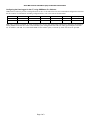
Configuring the Data Logger for the CT, using HOBOware Pro Software:
HOBOware Pro software provides a configuration file for the CT. The table below lists the recommended configuration values that
this file contains. For information on loading configuration files, refer to the software documentation.
Note: The CT requires 12-30VDC @ 35mA excitation power for 0-5 volts output option, which can be supplied by the FlexSmart
Analog Module (Onset Part No. S-FS-CVIA) with H22; by the Analog Sensor Port with U30; and by power adapter (Onset Part
No. AC-SENS-1) with ZW, U12, and UX120-006M. For the 4-20mA option, 15-30VDC @ 35mA will need to be provided.
Channel Name Raw Value 1 Raw Value 2 Scaled Value 1 Scaled Value 2 Scaled Units Min. Warm-up Time
Current 4mA 20mA 0 50 (or 100 or 200) A 8-10 sec.
Current 0V 5V 0 50 (or 100 or 200) A 8-10 sec.
Distributed by MicroDAQ.com, Ltd. www.MicroDAQ.com (603) 746-5524
-
 1
1
-
 2
2
-
 3
3


Veris T-VER-H970-200 Connection Instructions
- Type
- Connection Instructions
Ask a question and I''ll find the answer in the document
Finding information in a document is now easier with AI
Related papers
-
Veris PX3DLX02 Quick start guide
-
Veris CWE2C Installation guide
-
-
-
-
Veris HEW5VSTN Installation guide
-
-
-
Other documents
-
Onset T-SET-265-R25 Operating instructions
-
 Accessory Power GOgroove FlexSmart SP User manual
-
GOgroove FLEXSMART X2 User manual
-
-
-
-
-
 Hobo MX1102A Owner's manual
-
-

