Installation, Operation and Maintenance Manual
Installation, Operation and Maintenance Manual
4
1. Determine System Location (see Figures 1 and 2)
The Drinking Water Filtration System can be located under a sink or in a basement depending on space avail-
ability and preference. If a basement installation is selected, additional tubing, hardware and fittings may be
needed and a hole will have to be made from inside the cabinet, through the floor, to the basement.
Space Requirements
NOTE:Neverinstalltheltrationsysteminanareaofthehome
where the temperature may drop to freezing as damage to the
system will result.
The exact placement of the various components of the filtration
system will vary from installation to installation. The installer must
decide on where to place the faucet, tank and purification assembly
by balancing convenience with ease of installation and servicing.
Considerationsforanicemakerorotherremotehookupshouldbepredetermined,includingplumbingrout-
ing and any additional tools, fittings and tubing that may be required.
Feedwater Conditions Parameter
pH 4-11
Manganese <0.05ppm(mg/L)
Hardness <350ppm(mg/L)
HydrogenSulde Noneallowable
Iron(FE) <0.3ppm(mg/L)
Organics <1ppm(mg/L)
FreeChlorine Upto3ppm(mg/L)
Temperature 40-100°F(4-38°C)
Turbidity <1NTU
TDS Upto2,000ppm
Min./Max.Feedwaterpressure40-100psi(276-690kPa)
2. Prepare the Area for Installation
Determine where components will be located and how they will be mounted. Special mounting brackets
and hardware may be necessary to secure the system to a wall or ceiling joists if a basement installation is
called for. Inspect the cold water supply line and drain to determine if any additional fittings are required.
NOTE:Itisagoodideaatthistimetochecktheconditionoftheundercounterplumbingforanyexistingor
potential leaks.
3. Prepare the Drinking Water Filtration System for Installation
Opentheshippingcartonandremovecomponents.Checkthatalloftheinstallationpartsarepresentwhich
includethereverseosmosis(RO)assembly,storagetank,faucet,installationhardware,andtubinglocated
in box under storage tank.
If an optional percent rejection monitor is used, the probes should be installed at this time. Follow the in-
structions that come with the monitor.
14 5/8" NOM
6 1/2"
14 1/8" NOM
1 1/2"
Minimum Distance
Required To Remove
Cartridges
To reduce the risk associated with property damage due to
water leakage:
• Protect from freezing. Drain filter when temperatures drop below
40°F(4.4°C).
• Do notinstallifwaterpressureexceeds125psi(862kPa).If
yourwaterpressureexceeds125psi,youmust install a pres-
surelimitingvalve.Contactaplumbingprofessionalifyouare
uncertain how to check your water pressure.
CAUTION
5
4. Install the Feed Water Valve and Tubing (see Figure 3)
Thefeedwatersaddlevalveisdesignedforusewith3/8”to1/2”ODsoftcoppertubing(plainorchromed)and
rigid metal pipe. Do not use with flexible ribbed supply tubing or plastic pipe which require special hardware.
Soft Copper Tubing Installations:
A) Turnoffcoldwatervalveunderthesink,orthemainwatersupplyvalveforthehouse.
B) Beforeinstallingfeedwatersaddlevalve,makesurepiercinglancedoesnotprotrudebeyondrubber
gasket. See instructions on bag.
C) Assemblebothhalvesoffeedwatersaddlevalveoncoppertubing.
D) For3/8”O.D.tubing,usebracketwithsideprojectionstopreventdistortionoftubing.Use“V”sideofbracketfor
all larger size tubing. Tighten screws evenly and firmly — brackets should be parallel. Do not deform tubing.
E) Topiercesoftcoppertube,turnhandletotherightuntilitisrmlyseated.Thevalveisclosedinthisposition.
F) Turnonmainsupplyvalvetopressurizecoldwaterline.Checkforleaks.Ifvalvestemleaks,tighten
nut/seal with a wrench.
G)Connectlengthoforange1/4”tubingtofeedwatervalve,usingbrasscompressionnut,insertandplas-
ticsleeve(refertoFigure3).
Rigid Metal Pipe Installations:
A) Turnoffcoldwatersupplyvalveanddrainthelinetopreventspillage.
B) Drill3/16”holeatthedesiredlocation.Topreventshockhazard,useabatteryoperateddrill.
C) Turnvalvehandletotherighttoexposepiercinglancebeyondtherubbergasketnomorethan3/16”.
D) Assemblesaddlevalveonthesupplypipebyscrewingthetwohalvestogether.Usethe“V”sideofthe
bracket. Tighten screws evenly and firmly, keeping the two sides of the bracket parallel.
E) Turnsaddlevalvehandletotherighttoclosevalve.Ifvalvestemleaks,tightennut/sealaroundvalve
stem, with a wrench.
F) Connectlengthof1/4”orangetubingtothefeedwatervalve,usingbrasscompressionnut,insertand
plasticsleeve(refertoFigure3).
NOTE:Forbasementinstallations,alongerlengthoforangefeedwatertubingmayhavetobeused.
5. Prefill and Sanitize the Storage Tank
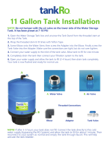
Prefilling the tank is always recommended so there is pressure to check for leaks and water to flush the
carbon filters. Tanks are furnished with a special disinfection capsule which sanitizes the tank when it is
filled with water. It is important to use a sanitizer when prefilling tank so the solution can sanitize the tubing,
fittings and faucet at the time of installation and startup.
A) Placetankonstand.
B) Removethesoftrubbercapfromthetankinlettting.
C) WrapPTFEtapetotheright(clockwise)ontothreads.
D) Poursanitizerintotank.
WARNING
To reduce the risk associated with eye, skin and respiratory and digestive tract burns from Calcium Hypo-
chlorite during installation:
•CalciumHypochlorite(CAS7778-54-3)granulesareusedfortanksanitationinthisproduct.
•Duringinstallation,donotgetineyesoronskinorclothing.Donotingest.Weareyeandfaceprotection.Keep
out of reach of children.
•Forfurthersafetyinformation,refertoMSDSdocumentsavailableatCHEMTREC(1-800-262-8200)orwww.3M.com.
• Somestateandlocalplumbingcodesmayprohibittheuseofsaddle-typevalvesand/ordrainconnections.See
page2forlistofstates.Optionalfeedvalveassembliescanbepurchased.Seepage15forfurtherinformation.
IMPORTANT NOTES


