Page is loading ...

Man024 Rev 4/21/06
PRIMUX
CAT5 KVM System
Installation and Operation Manual
PRIMUX
TM
Series
(
Host Ada
p
ter sold se
p
aratel
y)
NETWORK
TECHNOLOGIES
INCORPORATED
Tel:330-562-7070
Fax:330-562-1999
1275 Danner Dr
Aurora, OH 44202
www.networktechinc.com
NTI
R

i Man024 Rev 4/21/06
TRADEMARK
PRIMUX is a trademark of Network Technologies Inc in the U.S. and other countries.
COPYRIGHT
Copyright © 2004-2006 by Network Technologies Inc. All rights reserved. No part of this publication may be reproduced, stored
in a retrieval system, or transmitted, in any form or by any means, electronic, mechanical, photocopying, recording, or otherwise,
without the prior written consent of Network Technologies Inc, 1275 Danner Drive, Aurora, Ohio 44202.
CHANGES
The material in this guide is for information only and is subject to change without notice. Network Technologies Inc reserves the
right to make changes in the product design without reservation and without notification to its users.

Man024 Rev 4/21/06
ii
TABLE OF CONTENTS
INTRODUCTION.............................................................................................................................................................1
Materials ......................................................................................................................................................................1
FEATURES AND FUNCTIONS.......................................................................................................................................2
PREPARATION FOR INSTALLATION...........................................................................................................................3
Definitions....................................................................................................................................................................3
INSTALLATION...............................................................................................................................................................4
The Host Adapter.........................................................................................................................................................4
Installation of a PS/2 CPU........................................................................................................................................4
Installation of a USB CPU.........................................................................................................................................5
Installation of a SUN CPU ........................................................................................................................................5
Connecting the CAT5 cable to the Host Adapter......................................................................................................6
The User Station..........................................................................................................................................................6
Installation with PS/2 devices...................................................................................................................................6
Installation with USB devices....................................................................................................................................7
Connecting the CAT5 cable to the User Station.......................................................................................................8
Power Up for the first time........................................................................................................................................8
Daisy-Chained Host Adapters .....................................................................................................................................9
Adding a Host Adapter to a segment........................................................................................................................9
USING THE PRIMUX CAT5 KVM SWITCH .................................................................................................................10
Hot Plugging..............................................................................................................................................................10
Initial Startup............................................................................................................................................................10
User Rights vs. Administrator Rights......................................................................................................................10
Administrator Login and Password....................................................................................................................11
Setup Host Adapter(s)............................................................................................................................................11
Quick Connect.......................................................................................................................................................11
Change the Default Administrator Password.............................................................................................................11
Standards of Operation..............................................................................................................................................12
Keypad Control..........................................................................................................................................................12
Security......................................................................................................................................................................12
Administrator Login.................................................................................................................................................13
Autologin.................................................................................................................................................................13
User Login...............................................................................................................................................................13
User Access Functions..............................................................................................................................................13
Command Mode .....................................................................................................................................................13
Scan Mode..............................................................................................................................................................15
Normal Mode ....................................................................................................................
......................................15
Settings Menu.........................................................................................................................................................16
Find Host Adapter...................................................................................................................................................17
Host Adapter Info screen........................................................................................................................................17
Help Pages .............................................................................................................................................................18
OSD Settings Menu................................................................................................................................................18
Host Adapters for Scan...........................................................................................................................................19
Change Scan Dwell Time.......................................................................................................................................20
Video Quality Adjustment .......................................................................................................................................20
Administration............................................................................................................................................................21
Administration Menu...............................................................................................................................................21
Edit Hosts, Users, and User Station Info................................................................................................................22
Host Adapter List ....................................................................................................................................................22
Edit Host Adapter....................................................................................................................................................23
User List..................................................................................................................................................................24
User Info .................................................................................................................................................................25
Edit User.................................................................................................................................................................25
Add New User.........................................................................................................................................................26
Edit User Password ................................................................................................................................................27
Host Access List .....................................................................................................................................................27
Change Administrator's Password..........................................................................................................................28
Edit User Station.....................................................................................................................................................28
Select Autologon User............................................................................................................................................29

Man024 Rev 4/21/06
iii
User Station Info screen.........................................................................................................................................30
Idle Timeout............................................................................................................................................................30
Alternate OSD Key .................................................................................................................................................31
Update Firmware/Bootloader Menu........................................................................................................................32
Acquire/Send DDC Info ..........................................................................................................................................33
Configure MAC Host Adapters ...............................................................................................................................33
Select Keyboard Language ....................................................................................................................................34
TECHNICAL SPECIFICATIONS...................................................................................................................................35
INTERCONNECTION CABLE WIRING METHOD .......................................................................................................35
NULL MODEM CABLE PINOUTS ................................................................................................................................36
MENU QUICK-FIND KEYSTROKE TABLE..................................................................................................................37
SAFETY and EMC Regulatory Statements...................................................................................................................37
WARRANTY INFORMATION........................................................................................................................................38
TABLE OF FIGURES
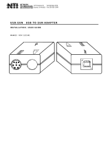
Figure 1- Typical Application..............................................................................................................................................................3
Figure 2- Connect a HA-PS2 Host Adapter to a PS/2 CPU...............................................................................................................4
Figure 3- Connect a HA-USB Host Adapter to a USB CPU...............................................................................................................5
Figure 4- Connect a HA-SUN Host Adapter to a SUN CPU...............................................................................................................5
Figure 5- Connect CAT5 cable to Host Adapter.................................................................................................................................6
Figure 6- Connect the Extended PS/2 components to the User Station ............................................................................................7
Figure 7- Connect extended USB components to the User Station...................................................................................................7
Figure 8- Connect CAT5 cable to User Station..................................................................................................................................8
Figure 9- Connect the AC adapter to the User Station.......................................................................................................................8
Figure 10- Daisy-chained Host Adapters...........................................................................................................................................9
Figure 11- PRIMUX-UZR front panel...............................................................................................................................................12
Figure 12- Login splash screen........................................................................................................................................................13
Figure 13- Command Mode main menu ..........................................................................................................................................14
Figure 14- Settings menu.................................................................................................................................................................16
Figure 15- Find Host Adapter screen...............................................................................................................................................17
Figure 16- Host Adapter Info screen................................................................................................................................................17
Figure 17- Help Pages for Command Mode ....................................................................................................................................18
Figure 18- OSD Settings Menu........................................................................................................................................................18
Figure 19- Host Adapters for Scan list.............................................................................................................................................19
Figure 20- Scan Dwell Time screen.................................................................................................................................................20
Figure 21- Video Adjustment Screen...............................................................................................................................................20
Figure 22- Administration Menu.......................................................................................................................................................21
Figure 23- Edit Menu .......................................................................................................................................................................22
Figure 24- Host Adapter List............................................................................................................................................................22
Figure 25- Edit Host Adapters menu................................................................................................................................................23
Figure 26- User List ...........................................................................................................
..............................................................24
Figure 27- User Info screen.............................................................................................................................................................25
Figure 28- Edit User menu...............................................................................................................................................................25
Figure 29- Submenus of the Edit User menu...................................................................................................................................26
Figure 30- User Password screen ...................................................................................................................................................27
Figure 31- Allow/Deny Access to Hosts screen...............................................................................................................................27
Figure 32- Administrator Password screen......................................................................................................................................28
Figure 33- Edit User Station screen.................................................................................................................................................28
Figure 34- Select user for Autologon ...............................................................................................................................................29
Figure 35- User Station Info screen.................................................................................................................................................30
Figure 36- Idle Timeout screen........................................................................................................................................................30
Figure 37- Alternate OSD screen.....................................................................................................................................................31
Figure 38- Update/Bootloader Menu................................................................................................................................................32
Figure 39- Select MAC Host Adapters screen.................................................................................................................................33
Figure 40- Select Keyboard Language menu ..................................................................................................................................34
Figure 41- View looking into RJ45 female........................................................................................................................................35

1
INTRODUCTION
The PRIMUX CAT5 KVM System (PRIMUX) is designed to enable the relocation of a VGA monitor, PS/2 or USB keyboard, and
mouse from up to 64 PS/2, SUN, or USB CPUs by as much as 1000 feet. The PRIMUX is comprised of one PRIMUX-UZR User
Station and at least one Host Adapter (HA-PS2, HA-USB, or HA-SUN) connected to a CPU to be controlled by the user. The
PRIMUX-UZR User Station supports PS/2 and USB user keyboard and mouse (devices). This manual describes the installation
and use of both components.
The PRIMUX Host Adapter and User Station are interconnected with either CAT5 Unshielded Twisted Pair (UTP) or Shielded
Twisted Pair (STP) cable, CAT5e cable, or CAT6 cable.
The PRIMUX Series CAT5 KVM System is extremely simple to install and has been thoroughly tested to insure reliable
performance. Through the use of CAT5, CAT5e, or CAT6 cable it is possible to economically increase the flexibility of a computer
system. Here are some of the features and ways this can benefit any workplace:
• Allows the placement of a monitor, keyboard, and mouse in a location where only these parts are needed without having
the CPU there too, taking up valuable space
• Allows any PS/2, USB, or SUN CPU to be accessed by a remote user (up to 1000 feet away)
• Additional RJ45 port on the Host Adapter allows the daisy-chaining of up to 64 Host Adapters providing user access to
up to 64 CPUs
• Control up to 64 CPUs from one keyboard, mouse, and monitor without "spaghetti" wiring
• Compatible with XGA, VGA, and SVGA systems
• Provides crisp and clear resolution up to 1024x768 /60Hz @ 1000 feet (using CAT5 UTP cable- see pg 35 for details)
• Video quality adjustment is automatic providing optimum image quality
• Allows for future expansion- buy what is needed now, add more later as desired
Supported Operating Systems
The PRIMUX is compatible with:
• Win9x • WinMe • Solaris
• WinNT • WinXP • MAC OS9.x , OSX
• Win2K • Linux 7.x, 8.0 • Others
Materials
Materials Supplied with this kit:
• NTI PRIMUX-UZR User Station
• 120VAC or 240VAC @ 50 or 60Hz -5VDC/2A AC Adapter
• Line cord, country specific
• Terminating Plug
• PRIMUX CDROM w/ Owner's Manual and Quick Start Guide (pdf files)
• Quick Start Guide (Printed)
Materials Not Supplied, but REQUIRED:
• NTI HA-PS2 PS/2 Host Adapter / HA-USB USB Host Adapter / HA-SUN Host Adapter (see pg. 4)
• CAT5/5e/6 unshielded twisted-pair cable(s) terminated with RJ45 connectors wired straight thru- pin 1 to pin 1, etc. (see pg.
35 for proper EIA/TIA 568B wiring method)
• A null modem cable will be required for future software updates (see specification on page 36).
Cables can be purchased from Network Technologies Inc by calling 800-RGB-TECH (800-742-8324) or (330)-562-7070 or by
visiting our website at www.networktechinc.com.

2
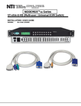
FEATURES AND FUNCTIONS
1. LED Display- for visual indication of which Host Adapter the user is connected to
2. Search Buttons- to enable manual search for desired Host Adapter connection
3. Favorite Buttons- programmable buttons to quick selection of specific Host Adapters
4. Power Switch- to turn the User Station ON an OFF
5. Cable Clamp- to secure the cable from the AC adapter
6. 5VDC 2A- 3.5mm power jack- for connection of AC adapter
7. RS232- DB9 male- serial communication port for updating firmware
8. USB Devices- USB Type A female- for connection of USB user devices (keyboard and mouse)
9. PS/2 Devices- green and purple 6mD females- for connection of PS/2 type mouse (green) and keyboard (purple)
10. SUN Devices- black 8mD female- for connection of SUN mouse and keyboard
11. Cat5 - RJ45 female- for connection of CAT5 cable between Host Adapter and User Station
11a. Yellow LED- power indicator- illuminates when power has been supplied to the unit
11b. Green LED- traffic indicator- illuminates when there is communication between the User Station and Host
Adapters.
12. Monitor- for connecting the video monitor
13. Video Connector- blue 15HD male- for connecting to the video port on the CPU
14. Mouse Connector- green male 6 miniDIN (HA-PS2 only)- for connecting to the mouse port on a PS2 CPU
15. Keyboard Connector- purple male 6 miniDIN (HA-PS2 only)- for connecting to the keyboard port on a PS2 CPU
15a. Device Connector- male USB Type A (HA-USB only)- for connecting to a device port on a USB CPU
15b. Device Connector- orange male 8 miniDIN (HA-SUN only) - for connecting to the device port on a SUN CPU
16. Cat5- RJ45 female- for connection of CAT5 cable between daisy-chained Host Adapters
R e a r V i e w o f P R I M U X - U Z R ( U s e r S t a t i o n )
1 1
C a t 5
M o n i t o r
S U N
D e v i c e s
P S / 2
D e v i c e s
M o u s e
K y b d
R S 2 3 2
U S B
D e v i c e s
5 V D C
2 A
-
+
+
P R I M U X
U Z R
T M
8
7654321
F a v o r i t e s
S e a r c h
U p
D o w n
C P U
N T I
R
N e t w o r k T e c h n o l o g i e s I n c
F r o n t V i e w o f P R I M U X - U Z R ( U s e r S t a t i o n )
4
5
6
7
8
9
1 0
1 1 b
1 1 a
1 2
1
2
3
N T I
N E T W O R K
T E C H N O L O G I E S
I N C O R P O R A T E D
T e l : 3 3 0 - 5 6 2 - 7 0 7 0
F a x : 3 3 0 - 5 6 2 - 1 9 9 9
1 2 7 5 D a n n e r D r
A u r o r a , O H 4 4 2 0 2
w w w . n t i 1 . c o m
R
H A - P S 2 ( P S / 2 H o s t A d a p t e r )
( F r o n t V i e w )
( R e a r V i e w )
1 1
1 1 a
1 1 b
1 3 1 4 1 5
1 6
1 5 a
1 5 b
( H o s t A d a p t e r s o l d s e p a r a t e l y )

3
PREPARATION FOR INSTALLATION
• Choose a location for the User Station such that cables from the keyboard, mouse, and monitor will reach it.
• The CAT5 cables must be run between the locations where the Host Adapter will be connected and User Station is
positioned. Be careful to route the cables away from any sources of magnetic fields or electrical interference that might
reduce the quality of the signal (i.e. AC motors, welding equipment, etc.) .
NOTE: The installer must ensure that all CAT5 cable between the Host Adapter and User Station, and between each Host
Adapter (if more than one) is of the straight-through type and not crossed.
• A 120V or 240V electrical supply (depending on the AC adapter being used) must be provided close enough to the position of
the User Station to plug the AC adapter into.
• All cables should be installed such that they do not cause stress on their connections to the equipment. Extended lengths of
cable hanging from a connection may interfere with the quality of that connection. Secure cables as needed to minimize
this.
• Properly shut down and disconnect the power from the CPU and devices to be extended. If other equipment is involved
whose connections are being interrupted, be sure to refer to the instruction manuals for that equipment for proper
disconnection and re-connection procedures before proceeding.
Definitions
Segment A single or series of CAT5 cable(s) from one user station to one or more Host Adapter(s)
that are daisy-chained together. A segment begins with the user station and ends with the
last Host Adapter in the daisy chain.
Master ID A unique number assigned by the administrator to a PRIMUX segment. It is used to identify
parts that have been configured by the master authority, particularly Host Adapters that
attempt to join the segment.
Master
Authority
The ultimate controlling authority in a segment (i.e. the master authority establishes the
unique I.D. for each Host Adapter). The master authority is part of the User Station.
String A set of characters, A-Z, 0-9, upper or lower case
Integer Any whole number (1,2,3…)
Unique ID Number identifying a Host Adapter to the master authority of a segment.
Figure 1- Typical Application
P R I M U X
U Z R
T M
8
7654321
F a v o r i t e s
S e a r c h
U p
D o w n
C P U
N T I
R
N e t w o r k T e c h n o l o g i e s I n c
F r o n t V i e w o f P R I M U X - U Z R
C A T 5 C a b l e
C A T 5 C a b l e
C A T 5 C a b l e
U P T O 1 0 0 0 '
C P U 6 4C P U 2C P U 1
P S / 2 ,
U S B ,
O R S U N
P S / 2 ,
U S B ,
O R S U N
P S / 2 ,
U S B ,
O R S U N
H o s t
A d a p t e r
H o s t
A d a p t e r
H o s t
A d a p t e
r
V G A
M u l t i - S c a n
M o n i t o r
S U N K e y b o a r d / M o u s e

4
INSTALLATION
The Host Adapter
The PRIMUX HA Host Adapter is designed to support PS/2, SUN, and USB CPUs. For PS/2 CPUs use HA-PS2, for SUN
CPUs use HA-SUN, and for USB CPUs use HA-USB. Before installing or removing a Host Adapter, power down the CPU to be
connected/disconnected and disconnect the power cord from the CPU.
CAUTION!
D
AMAGE MAY OCCUR TO THE
CPU
AND
H
OST
A
DAPTER IF POWER IS NOT DISCONNECTED BEFORE
CONNECTING OR DISCONNECTING CABLES
.
Installation of a PS/2 CPU
Plug the cables of the HA-PS2 Host Adapter into the back of the CPU after disconnecting the power cord from the CPU.
(See Fig. 2.)
a) Connect the purple 6 pin miniDIN cable end with the keyboard symbol
on it to the keyboard port on the back of the CPU.
b) Connect the green 6 pin miniDIN cable end with the mouse symbol
on it to the mouse port on the back of the CPU.
c) Connect the blue 15HD cable end to the VGA port on the back of the CPU.
Figure 2- Connect a HA-PS2 Host Adapter to a PS/2 CPU
PS/2 Mouse
PS/2 Keyboard
( F r o n t V i e w )
R e a r V i e w o f P S / 2 C P U
1 5 H D m a l e
v i d e o c o n n e c t o r
1 5 H D f e m a l e
v i d e o c o n n e c t o r
H A - P S 2
6 p i n m i n i D I N
f e m a l e c o n n e c t o r s
6 m i n i D I N
m a l e c o n n e c t o r s
p u r p l e - k e y b o a r d
g r e e n - m o u s e

5
Installation of a USB CPU
Plug the cables of the HA-PS2 Host Adapter into the back of the CPU after disconnecting the power cord from the CPU. (See
Fig. 3.)
a) Connect the cable with the USB Type A male cable end on it to a USB Type A female port on the back of the
CPU.
b) Connect the blue 15HD cable end to the video connector on the back of the CPU.
Figure 3- Connect a HA-USB Host Adapter to a USB CPU
Installation of a SUN CPU
Plug the cables of the HA-SUN Host Adapter into the back of the CPU after disconnecting the power cord from the CPU.
(See Fig. 4.)
a) Connect the orange 8 pin miniDIN cable end on it to the devices port on the back of the CPU.
b) Connect the blue 15HD cable end to the VGA port on the back of the CPU.
Figure 4- Connect a HA-SUN Host Adapter to a SUN CPU
FYI: The HA-SUN Host Adapter does not provide startup key support for SUN CPUs.
USB Devices
SUN Devices
( F r o n t V i e w )
R e a r V i e w o f U S B C P U
1 5 H D m a l e
v i d e o c o n n e c t o r
1 5 H D f e m a l e
v i d e o c o n n e c t o r
H A - U S B
U S B T y p e A m a l e
U S B T y p e A
d e v i c e p o r t
R e a r V i e w o f S U N C P U
( F r o n t V i e w )
H A - S U N
o r a n g e - d e v i c e s
1 5 H D f e m a l e
v i d e o c o n n e c t o r
8 p i n m i n i D I N
f e m a l e c o n n e c t o r

6
H A - P S 2
( R e a r V i e w )
C A T 5 C a b l e
t o U s e r S t a t i o n
C a b l e t o C P U
T e r m i n a t i n g
P l u g ( S u p p l i e d )
Connecting the CAT5 cable to the Host Adapter
Connect CAT5 cable to the “OUT” port on the Host Adapter. (See Fig. 5.) When properly inserted the cable end should snap into
place. Also be sure to insert the Terminating Plug into the "IN" port on the Host Adapter if this is the only Host Adapter in the
segment. Otherwise, see "Daisy-Chained Host Adapters" on page 9 to add more Host Adapters to the segment.
NOTE: If an RJ45 wall outlet is being used, connect the other end of the extension cable
to the RJ45 wall outlet.
WARNING: Never connect the PRIMUX Host Adapter to an Ethernet card,
Ethernet router, hub or switch or other Ethernet RJ45 connector of an Ethernet
device. Damage to devices connected to the Ethernet may result.
NOTE: The installer must ensure that all CAT5 cable between the Host Adapter
and User Station is of the straight-through type and not crossed.
Figure 5- Connect CAT5 cable to Host Adapter
The User Station
The PRIMUX-UZR User Station can be used with either PS/2 devices or USB devices.
NOTE: If the user keyboard connected is PS/2 (6mD connector), then the mouse must also be PS/2. If the user
keyboard is USB (USB Type A connector), then the mouse must also be USB.
Installation with PS/2 devices
1. Position the User Station such that the CAT5 cable, the monitor cable, device cables, and the AC adapter power connector
can each reach the User Station without cable strain.
2. Connect the monitor cable to the female 15HD video connector on the User Station.
3. Connect the PS/2 device(s) to the User Station (see Fig. 6).
a. Connect the keyboard to the purple female 6 pin miniDIN connector on the User Station.
b. Connect the mouse to the green female 6 pin miniDIN connector on the User Station.
!

7
Figure 6- Connect the Extended PS/2 components to the User Station
Installation with USB devices
1. Position the User Station such that the CAT5 cable, the monitor cable, device cables, and the AC adapter power connector
can each reach the User Station without cable strain.
2. Connect the monitor cable to the female 15HD video connector on the User Station.
3. Connect the USB device(s) to the User Station (see Fig. 7).
a. Connect the keyboard to a USB Type A female connector on the User Station.
b. Connect the mouse to the other USB Type A female connector on the User Station.
Figure 7- Connect extended USB components to the User Station
V G A
M u l t i - S c a n
M o n i t o r
1 5 H D m a l e
v i d e o c o n n e c t o r
P S / 2
M o u s e
P S / 2 K e y b o a r d
6 m i n i D I N
m a l e c o n n e c t o r s
C a t 5
M o n i t o r
S U N
D e v i c e s
P S / 2
D e v i c e s
M o u s e
K y b d
R S 2 3 2
U S B
D e v i c e s
5 V D C
2 A
-
+
N E T W O R K
T E C H N O L O G I E S
I N C O R P O R A T E D
T e l : 3 3 0 - 5 6 2 - 7 0 7 0
F a x : 3 3 0 - 5 6 2 - 1 9 9 9
1 2 7 5 D a n n e r D r
A u r o r a , O H 4 4 2 0 2
w w w . n t i 1 . c o m
N T I
R
+
R e a r V i e w o f
P R I M U X - U Z R U s e r S t a t i o n
1 5 H D f e m a l e
v i d e o c o n n e c t o r
6 p i n m i n i D I N
f e m a l e c o n n e c t o r s
C a t 5
M o n i t o r
S U N
D e v i c e s
P S / 2
D e v i c e s
M o u s e
K y b d
R S 2 3 2
U S B
D e v i c e s
5 V D C
2 A
-
+
N E T W O R K
T E C H N O L O G I E S
I N C O R P O R A T E D
T e l : 3 3 0 - 5 6 2 - 7 0 7 0
F a x : 3 3 0 - 5 6 2 - 1 9 9 9
1 2 7 5 D a n n e r D r
A u r o r a , O H 4 4 2 0 2
w w w . n t i 1 . c o m
N T I
R
+
P R I M U X - U Z R U s e r S t a t i o n
U S B T y p e A m a l e
V G A
M u l t i - S c a n
M o n i t o r
1 5 H D m a l e
v i d e o c o n n e c t o r
1 5 H D f e m a l e
v i d e o c o n n e c t o r
U S B
M o u s e
U S B K e y b o a r d
U S B T y p e A f e m a l e
d e v i c e p o r t s

8
Connecting the CAT5 cable to the User Station
Make sure the CAT5 cable has been installed in accordance with the “Preparation for Installation” instructions on page 3.
Connect the CAT5 cable to the “Cat 5” port on the User Station. (See Fig. 8.) When properly inserted the CAT5 cable end should
snap into place.
WARNING: Never connect the PRIMUX-UZR User Station to an Ethernet card, Ethernet router, hub or switch
or other Ethernet RJ45 connector of an Ethernet device. Damage to devices connected to the Ethernet may
result.
Figure 8- Connect CAT5 cable to User Station
NOTE: If an RJ45 wall outlet is being used, connect the other end of the extension cable to the RJ45 wall outlet.
Power Up for the first time
Note: The user devices, monitor, and CAT5 cable should already be connected before powering up the User Station
.
1. Connect the AC adapter power connector to the 5VDC port on the User Station (see Fig. 9). Plug the AC adapter into a
power outlet. The yellow LED on the RJ45 connector of the User Station should illuminate, indicating that a proper power
connection has been made to it.
2. Re-connect the power cord to the CPU.
FYI: The Host Adapter is powered by the CPU.
3. Power up the monitor.
Figure 9- Connect the AC adapter to the User Station
4. With the User Station and Host Adapter connected via CAT5 cable, refer to "Using the PRIMUX CAT5 KVM Switch" on
page 10.
FYI: The green LED on each RJ45 connector will illuminate anytime data traffic is passing between the Host Adapter and
User Station, indicating proper CAT5 cable connection and communication. (See Fig. 9)
!
C A T 5 c a b l e
t o M a t r i x S w i t c h
R J 4 5 m a l e
C A T 5 c o n n e c t o r
C a t 5
M o n i t o r
S U N
D e v i c e s
P S / 2
D e v i c e s
M o u s e
K y b d
R S 2 3 2
U S B
D e v i c e s
5 V D C
2 A
-
+
N E T W O R K
T E C H N O L O G I E S
I N C O R P O R A T E D
T e l : 3 3 0 - 5 6 2 - 7 0 7 0
F a x : 3 3 0 - 5 6 2 - 1 9 9 9
1 2 7 5 D a n n e r D r
A u r o r a , O H 4 4 2 0 2
w w w . n t i 1 . c o m
N T I
R
+
R e a r V i e w o f P R I M U X - U Z R U s e r S t a t i o n
B a r r e l
( I n s i d e
b a r r e l )
( O u t s i d e
b a r r e l )
P o w e r C o n n e c t o r
2 . 1 m m x 5 . 5 m m F e m a l e
5 V D C @ 2 . 0 A O U T P U T
G r e e n C o m m u n i c a t i o n L E D
Y e l l o w P o w e r L E D
5 V D C
A C
A D A P T E R
R e a r V i e w o f P R I M U X - U Z R
C a t 5
M o n i t o r
S U N
D e v i c e s
P S / 2
D e v i c e s
M o u s e
K y b d
R S 2 3 2
U S B
D e v i c e s
5 V D C
2 A
-
+
N E T W O R K
T E C H N O L O G I E S
I N C O R P O R A T E D
T e l : 3 3 0 - 5 6 2 - 7 0 7 0
F a x : 3 3 0 - 5 6 2 - 1 9 9 9
1 2 7 5 D a n n e r D r
A u r o r a , O H 4 4 2 0 2
w w w . n t i 1 . c o m
N T I
R
+
R e a r V i e w o f P R I M U X - U Z R U s e r S t a t i o n

9
Daisy-Chained Host Adapters
Up to 64 Host Adapters can be connected in a daisy-chain to a create a segment of CPUs that are controlled by a single user from
a User Station. The first Host Adapter is connected to the User Station via the "OUT" port. The additional Host Adapters in the
segment will have CAT5 cable going from their "OUT" port to another Host Adapter's "IN" port to enable communications between
the user and each CPU in the system, as shown in Fig. 10. A Terminating Plug must be installed in the "IN" port of the last
Host Adapter in the segment.
NOTE: The installer must ensure that all CAT5 cable terminations between each Host Adapter are of the straight-through
type (pin 1 to pin 1, pin 2 to pin 2, etc.) and not crossover.
NOTE: The total length of the CAT5 cable from the User Station to the last Host Adapter in the daisy-chain must not
exceed 1000'.
Figure 10- Daisy-chained Host Adapters
Adding a Host Adapter to a segment
When adding a Host Adapter to a segment, whether at the end, or inside the chain (between two other Host Adapters connected
together), the administrator must follow some simple steps:
1. Make sure the Host Adapter being connected to a CPU is the proper type for the CPU.
CPU TYPE HOST ADAPTER MODEL
PS/2 HA-PS2
USB HA-USB
SUN HA-SUN
2. Determine what name the Host Adapter will be identified as in the Host Adapter list (should be unique to all other known hosts
in the segment).
3. Follow the installation instruction on page 3 for Host Adapters and for above for Daisy-Chained Host Adapters.
FYI: A Host Adapter can be added to the last Host Adapter in the chain, or between two existing Host Adapters.
NOTE: Do NOT attach a Host Adapter to a CPU or disconnect a Host Adapter from a CPU while the CPU is connected to
power. Disconnect the power cord first, then connect or disconnect the Host Adapter. Failure to do so may result in
damage to the Host Adapter or CPU.
4. Once the installation procedure is complete the connected CPU can be powered up.
5. This Host Adapter will be auto discovered by the master authority. It will identify itself as "(NEW PS2 HA)" , "(NEW USB
HA)", or "(NEW SUN HA)".
6. The administrator should assign a unique name to the Host Adapter (see page 23)
7. All users will have default access to the new Host Adapter unless the Administrator configures the access otherwise (see
page 26).
8. Once access controls have been set, the administrator should verify the security access to the new Host Adapter.
H A - P S 2
( R e a r V i e w )
C A T 5 C a b l e
t o U s e r S t a t i o n
C a b l e t o C P U 1
H A - P S 2
( R e a r V i e w )
C a b l e t o C P U 2
H A - P S 2
( R e a r V i e w )
C a b l e t o C P U 3
H A - P S 2
( R e a r V i e w )
C a b l e t o C P U 6 4
C A T 5 C a b l e
C A T 5 C a b l e
C A T 5 C a b l e
C A T 5 C a b l e
T e r m i n a t i n g
P l u g ( S u p p l i e d )
L a s t H o s t
A d a p t e r i n
t h e s e g m e n t

10
USING THE PRIMUX CAT5 KVM SWITCH
The PRIMUX CAT5 KVM System is designed to enable a user to control as many as 64 PS/2, USB, and SUN CPUs (any mixture
of each) from a single User Station as much as 1000 feet from the farthest CPU. Control is achieved through the use of either
the keypad on the front panel or On Screen Display (OSD) Menus. Access to one or more CPUs is determined by the security
configuration of the PRIMUX as set by the administrator. Once user access limitations are defined, the user can select which
CPU to connect to using either the OSD menu, the "Search" buttons on the front of the User Station, or quickly make a selection
after programming the "Favorite" buttons.
Hot Plugging
The PRIMUX-UZR is designed to emulate the presence of a mouse and keyboard whenever the PRIMUX-UZR is powered up.
As a result, the keyboard and mouse may be hot-plugged from the User Station at any time without causing a CPU error.
Note: Device types cannot be changed when hot-plugging. If the device type is changed (i.e. from PS/2 to USB), the
PRIMUX-UZR must be power cycled (turned OFF, then ON again) for the device to work properly.
Note: Both devices must be either PS/2 or USB. There cannot be one of each connected to the User Station.
The PRIMUX Host Adapter may also be hot-plugged to a CPU, provided the CPU and the operating system supports device hot-
plugging. (Operating systems known to support hot-plugging include Windows 2000 SP3 and higher, Windows XP, and Linux
2.6 and higher. )
CAT5 cables can be hot plugged. If the CAT5 cable is disconnected, the User Station will continue to monitor all Host Adapters
in the Host Adapter List.
FYI: Once a Host Adapter is selected by the User Station it will stay connected or attempt to connect forever if the
selected Host Adapter is powered OFF or the CAT5 cable is disconnected. To properly remove a Host Adapter, the user
must delete it from the Host Adapter List (page 23).
Hot plugging a Host Adapter to an NTI VOPEX splitter is not recommended. If communication is lost, send a "Reset Host"
command (page 23 ) from the User Station to restore communication.
Initial Startup
After installing the User Station and one or more Host Adapters as described on pages 3-6, when first applying power the user
will be prompted to supply a Master ID number. The Master ID number is any number from 0 to 65523. This number will be the
Master ID of the segment. All Host Adapters added to the segment will be configured with this number to become part of the
segment.
Note: The PRIMUX User Station cannot be used to control anything until the Master Identification number has been
properly set.
Note: If more than one segment will be configured, be sure to assign a unique Master ID number to each.
Following assignment of the Master ID number, the NEW_USER1 will be automatically logged-in and the Command Mode menu
will appear. By default, access is given to all Host Adapters and their connected CPUs, and Scan Mode will scan all connected
CPUs.
User Rights vs. Administrator Rights
Before continuing, the user should consider what action is going to be taken. The User and Administrator of the PRIMUX CAT5
KVM system have different roles and control over what the PRIMUX does.
Administrator Rights Include:
¾ Change the Administrator Password
¾ Assign, edit, and remove user names and passwords
¾ Define user access rights to CPUs in the segment
¾ Adding and configuring Host Adapters in the segment
¾ Configure operating parameters of the User Station
¾ Update DDC information between the monitor and CPUs
FYI: Users can be given full administrative access rights by the administrator.

11
User Rights Include:
¾ The ability to connect the user's keyboard, mouse, and monitor to CPUs (only those CPUs that have been granted
access by the administrator).
¾ The ability to enable/disable Scan Mode
¾ The ability to change the sorting method of Host Adapters by index number or alphabetically
Administrator Login and Password
To login as the administrator, press <L> to logout as NEW_USER1 and the login splash screen will appear. While holding down
the <Shift> key, enter an administrator name and default password:
administrator names = ROOT or ADMINISTRATOR (either can be used)
default administrator password = NTI
With a successful login, the administrator can setup additional users (see page 24).
FYI: The User Station can be configured to Autologon a specific user (page 29) with each User Station power up or have
a Login splash screen appear for the user to login to the User Station. The administrator can also configure the User
Station to autoconnect a user to a specific Host Adapter at logon by configuring the Logon Host and Action on Logon in
the Edit User menu (page 25). For more on setting up users, see page 25.
Setup Host Adapter(s)
No initial configuration of the Host Adapter is required for it to be identified by the User Station in the segment. Once discovered
it appears in the segment, and the Master Authority assigns the Host Adapter its Unique ID value. This value is used to
¾ set its identity for the security allow/deny access attribute (page 26)
¾ set its identity in the list of Host Adapters/CPUs that can be scanned in Scan Mode (page 19)
The Unique ID is stored in the Host Adapter and saved there, even if power is removed.
Quick Connect
From the Command Mode menu, to make connection to any Host Adapter in the segment,
press <G> followed by the index number (see pg 14) of the desired Host Adapter,
press <Enter> to select it,
press <Enter> again to connect to it.
-OR-
use the mouse to select the desired Host Adapter to connect to and click on it to connect.
Press <X> or <Esc> to exit Command Mode and use the connected CPU connected to the selected Host Adapter.
Press <Ctrl> + <`> to return to Command Mode (see pg 13).
Change the Default Administrator Password
Once the administrator is logged in, it is recommended that the the administrator change the default administrator password.
To change the administrator password:
- Press A (Administration Menu) - E (Edit Menu) - U (Edit User Menu) - P (Change Root Password)
- Enter the current password (default is "NTI")
- Enter the new password (case sensitive, 16 characters maximum, alphanumerc)
- Press <Enter>
- Re-enter to confirm the new password
- Press <Enter> to finish, or <Tab> to enter the password again.
Note: In the event the password is forgotten, contact NTI for instruction on how to reset the password to the default
"NTI".
FYI: When the password is changed for user ROOT , it automatically changes for user ADMINISTRATOR as well.

12
Standards of Operation
Throughout this manual, various standards of operation apply to the menus used to control and operate the PRIMUX.
• OSD menus can be navigated by the up and down arrows on the keyboard, as well as the <Page Up>, <Page Down>,
<Home>, and <End> keys.
- The up and down arrows increment/decrement one line item at a time
- <Page Up> and <Page Down> increment/decrement by one page at a time
- <Home> will jump to the beginning of the list
- <End> will jump to the end of the list.
• The scroll bar in a list can be used by clicking on the corresponding up and down arrow above and below the scroll
bar.
• The mouse wheel may be used to move the selection bar
• Functions that are "Administrator Only" are also available to users having administrative rights (see page 25).
• Placing the mouse over a listed Host Adapter highlighting the listed item with a blackened background "selects" the
Host Adapter. Clicking on it while in Command Mode will connect to that Host Adapter.
• Available functions will have white characters with one red character. The background of available functions will
become green when the mouse pointer is positioned over the function. Functions that are not available will be
transparent.
• When pressing a letter is called for to select a function, press either the corresponding key on the keyboard or use
the mouse to select the function.
• To exit any menu, press <Esc> or <X> on the keyboard or click on "Esc" in the menu.
• When "+" is shown between keystrokes, it indicates a chorded sequence (press and hold the keys consecutively
until all keys in the sequence are pressed). I.e. <Ctrl>+<`> is a chorded sequence to enter Command Mode.
• When "-" is shown between keystrokes, it indicates to press the keys consecutively (press and release one at a time)
• Press <F10> to return directly to the Command Mode menu
Figure 11- PRIMUX-UZR front panel
Keypad Control
The keypad on the front panel of the PRIMUX User Station enables a user to quickly set the User Station to connect to the desired
CPU. Two seven-segment LEDs illuminate to show the index number of the Host Adapter the user is connected to. The Up and
Down buttons enable the user to search for the desired CPU. The Favorite buttons, 1-8, can be programmed for quick selection
of the most commonly connected CPUs. (See Fig. 11) By default, the Favorite buttons 1-8 are pre-programmed to connect to
Host Adapters 1-8.
To program a Favorite button,
- Use the Search buttons to select the desired Host Adapter index number to connect with (or use OSD Command
Mode).
- With the index number in the LED display, press and hold the Favorite button to be associated with it for at least 2
seconds. The LED will blink when the selection is remembered and until the Favorite button is released.
- When this button is pressed, the User Station will immediately connect to the selected Host Adapter.
- Repeat for each Favorite button to be programmed.
Note: Favorite buttons are not available when PRIMUX is mounted in a RACKMUX-15/17-PRIMUX drawer.
Security
The PRIMUX CAT5 KVM System is designed with security to prevent unauthorized use of the CPUs connected as determined by
the administrator. Up to 16 users may be given access to the system, each with individual limitations of use. Only the
administrator or user with administrative privileges can activate or deactivate the security features on each user port. Finally, the
administrator can set a maximum idle time value after which the current user will be logged out and the login splash screen
displayed again. The current security status, idle time out, and scan dwell time are all saved and will be restored whenever
power to the User Station is cycled OFF, then ON. To reset the administrator’s password call NTI and have the device serial
number of the PRIMUX User Station available.
P R I M U X
U Z R
T M
8
7654321
F a v o r i t e s
S e a r c h
U p
D o w n
C P U
N T I
R
N e t w o r k T e c h n o l o g i e s I n c

13
Administrator Login
To access the OSD menu Command Mode from the keyboard press the <Ctrl> + <`> (accent key). (An additional alternate OSD
key may be defined, see page 31) The User Login screen will automatically appear on the monitor. In order to configure the
PRIMUX, when the PRIMUX is powered ON, the administrator can login with a proper user name and password. While holding
down the <Shift> key, enter the following;
administrator names = ROOT or ADMINISTRATOR (either can be used)
default administrator password = NTI
FYI: The names for the administrator cannot be changed.
Once logged-in, follow the instructions on pages 10 or 27 for changing the password. Once the password is setup, if it is lost or
forgotten the administrator will have to contact NTI for assistance on clearing the password and set it up again. The administrator
can setup each of the users (page 26) and the limitations of their use of the individual CPUs from within Administration Mode.
Autologin
By default, the user account NEW_USER1 has been configured to automatically login at power-up. The adminstrator may
reconfigure the User Station to autologin a different user (page 28) or have a Login splash screen appear at power-up requiring a
user to login, with or without a password). The autologin user uses CPUs listed in its Host Allow/Deny Access List as configured
by the administrator (page 26).
User Login
The administrator may configure the User Station to require each user to login using a predefined password to gain access rights
to CPUs and to the features in the OSD menus. Once logged in, the user may be directed to either a specific CPU (provided the
CPU is powered ON), or to the OSD menu where the user can decide what action is to be taken. The initial action (Action on
Logon- page 25) and whether or not to connect to a specific Host Adapter (Logon Host- page 25) will be configured by the
administrator.
Once logged-in a user can use the Command Mode functions described below and on page 14 to control the segment of CPUs
within the limitations as determined by the administrator.
Function Keystroke
Add a character to the user
name/password
A-Z, 0-9
Max. 16 characters
Remove previous character from
the user name/password
Backspace
Submit user name/password Enter or Tab
Figure 12- Login splash screen
User Access Functions
Command Mode
In order to control the User Station with the keyboard, Command Mode must be enabled. To enable Command Mode from the
keyboard:
Press
All the status lights on the keyboard will illuminate to indicate that Command Mode is enabled. At this point, the Command Mode
menu will be displayed.
If the password submitted is incorrect, the user will
not be able to proceed.
If the password submitted is correct, the user will
either proceed to a CPU chosen by the
administrator and operate in Normal Mode, or
proceed to the Command Mode menu.
`
+
Ctrl
~
(ACCENT
KEY)
`

14
The Command Mode menu (see Fig. 13) lists all Host Adapters by name and index number. Only 8 Host Adapters are listed on
the screen at a time. To view the other portions of the list, scroll using the arrow keys on the keyboard or use the mouse to click
on the arrows on the scroll bar in the OSD menu. When the Command Mode main menu is first displayed, the first Host Adapter
listed will be the Host Adapter the current user is connected to, followed by the next seven consecutively numbered ports.
(Alternatively the list may be sorted alphabetically- see Settings Menu on page 15 to toggle sort method.) The names of
accessible Host Adapters are displayed with white characters. The access rights for the user logged-in may not include all Host
Adapters. Names of restricted access Host Adapters are displayed in blue.
An arrow to the left of an index number in the list indicates the Host Adapter the user is currently connected to. From left to right,
the columns display the following:
• Index Number
• Host Adapter Name
• Type of Host Adapter connected (PS2, SUN, or USB)
• CPU power status (where "p" means ON and " - " means OFF)
Figure 13- Command Mode main menu
The list below describes the command functions available from the keyboard within the OSD mode of control after entering into
Command Mode:
Function Keystroke
Select the previous Host Adapter Up Arrow
Select the next Host Adapter Down Arrow
Decrements the menu by 1 page (displays the previous 7 Host Adapters) Page Up
Increments the menu by 1 page (displays the next 7 Host Adapters)
Page Down
Display first 8 Host Adapters and move selection bar to the first Home
Display last 8 Host Adapters and move selection bar to the last End
Press to toggle enable/disable Scan Mode S
Enter Settings Menu T
Find a Host Adapter (using name, comment, unique ID, index number) F
Enter Administration Mode (Administrator only- see page 20)
A
Display info for the selected Host Adapter/User Station I
Display Command Mode Help Menu H or F1
Go to - select Host Adapter by index number G
Search- select Host Adapter by name R
Commands for submenus
Index Numbe
r
Type of Host
A
da
p
te
r
CPU Power
Status
Home
Page Up
Up One
End
Page Down
Down One
Host Adapter Name
Logged-in use
r
Arrow indicates currently
connected Host Adapter
Mouse
Controls
Selection Bar
Mouse Cursor
FYI: A red hourglass will appear
near the upper right corner of the
OSD menu to indicate that the
screen is being refreshed. This
will occur after 5 seconds of
keyboard and mouse inactivity..

15
Function Keystroke
Connect to the highlighted Host Adapter Enter or Spacebar
Log Out the User/Administrator and disconnect from the Host Adapter
(The login screen will appear)
L
Exit Command Mode without logging out X or Esc
The mouse can also be used to control the User Station Command Mode.
• The scroll wheel can be used to scroll through the Host Adapters list.
• The mouse cursor can be moved to the any of the command fields where the user can click on
the left mouse button to select that function.
• Host Adapters listed on the screen can be selected by moving the cursor onto a Host Adapter.
• To connect to a Host Adapter, click on the selected Host Adapter.
• To move through the Host Adapter list, the scroll bar to the right of the list can be used by clicking the up and
down arrows.
Note: Exit Command Mode to enter Normal Mode and control the connected CPU. To exit Command Mode, press <Esc>
or click the “ESC” command on the screen with the mouse.
Scan Mode
To activate Scan Mode press <S> from the Command Mode menu.
Scan Mode enables the user to scan through selected Host Adapters and to have full device control of the connected Host
Adapter. From the Settings menu (below) the user can edit the list of Host Adapters that can be scanned. A Host Adapter is
skipped from the scan cycle if one of the following conditions is true:
• the Host Adapter is not in the scan list
• the user does not have access rights to the Host Adapter
When switching to a new Host Adapter the Host Adapter name is displayed by OSD for 5 seconds or until a key is pressed or the
mouse is moved, whichever comes first. The scan dwell time is programmable from 2 to 255 seconds (default time-out period is 5
seconds). When the user moves the mouse or types on the keyboard the scanned Host Adapter becomes active and scanning is
stopped. The switch will resume scanning after a period of user inactivity determined by the scan dwell time. See Settings Menu
below for configuring the scan dwell time.
Note: The keyboard and mouse must remain idle for the full scan dwell time before the switch selects the next active
Host Adapter.
Normal Mode
When the User Station is not in Command or Scan mode and the OSD control is not active on the monitor, the user is in Normal
Mode, controlling the CPU to which the user is connected through the PRIMUX switch.

16
Settings Menu
To enter the Settings Menu, press <T> from the Command Mode Menu.
Figure 14- Settings menu
Settings Menu
Function Description Keystroke
OSD Settings Enables the user to reposition or resize the OSD
menu on the monitor
O
Numeric Host List or
Alphabetic Host List
Toggle between listing Host Adapters by
reference number vs alphabetically by name
I
Hosts for Scan Choose CPUs to be scanned S
Change Scan Dwell Time Set length of time a user can dwell (no keyboard
or mouse action) before PRIMUX will
automatically scan to the next accessible CPU
T
Adjust Video Quality Adjust the video quality to improve the screen
image
V
Esc Exit the Settings menu X or Esc
FYI: CPUs will only be scanned if the user has been allowed access to the CPU (See "Allow/Deny Access To Hosts" on
page 26) by the administrator.
FYI: Functions S,T, and V are not available when the "ROOT" user is logged in. The "ROOT" user cannot connect to a
Host Adapter. The "ROOT" user is able to perform administrative tasks only.
/