
ID TECH
10721 Walker Street, Cypress, CA 90630-4720
Tel: (714) 761-6368 Fax (714) 761-8880
www.idtechproducts.com support@idtechproducts.com
ViVOpay Kiosk III
User Manual
80136500-001 Rev. N
14 August 2023

ViVOpay Kiosk III User Manual
Page | 2
Copyright© 2023, International Technologies and Systems Corporation. All rights reserved.
ID TECH
10721 Walker Street
Cypress, CA 90630
(714) 761-6368
www.idtechproducts.com
This document, as well as the hardware and software it describes, is furnished under license and may
only be used in accordance with the terms of such license. The content of this paper is furnished for
informational use, subject to change without notice, and not to be construed as a commitment by ID
TECH. ID TECH assumes no responsibility or liability for any errors or inaccuracies that may appear in
this document.
Except as permitted by such license, no part of this publication may be reproduced or transmitted by
electronic, mechanical, recorded, or any other method, or translated into another language or
language form without the express written consent of ID TECH. ID TECH is a registered trademark of
International Technologies and Systems Corporation. ViVOpay and Value through Innovation are
trademarks of International Technologies and Systems Corporation. Other trademarks are the
property of the respective owner.
Warranty Disclaimer
The services and hardware are provided "as is" and "as-available," and the use of these services and
hardware are at the user’s own risk. ID TECH does not make, and hereby disclaims, any and all other
express or implied warranties, including, but not limited to warranties of merchantability, title, fitness
for a particular purpose, and any warranties arising from any course of dealing, usage, or trade
practice. ID TECH does not warrant that the services or hardware will be uninterrupted, error-free, or
completely secure.

ViVOpay Kiosk III User Manual
Page | 3
FCC warning statement
This device complies with Part 15 of the FCC Rules. Operation is subject to the following two conditions: (1) this
device may not cause harmful interference, and (2) this device must accept any interference received, including
interference that may cause undesired operation.
The user manual for an intentional or unintentional radiator shall caution the user that changes or modifications
not expressly approved by the party responsible for compliance could void the user’s authority to operate the
equipment.
Note: The grantee is not responsible for any changes or modifications not expressly approved by the party
responsible for compliance. Such modifications could void the user’s authority to operate the equipment.
Note: This equipment has been tested and found to comply with the limits for a Class B digital device, pursuant
to part 15 of the FCC Rules. These limits are designed to provide reasonable protection against harmful
interference in a residential installation. This equipment generates uses and can radiate radio frequency energy
and, if not installed and used in accordance with the instructions, may cause harmful interference to radio
communications. However, there is no guarantee that interference will not occur in a particular installation. If
this equipment does cause harmful interference to radio or television reception, which can be determined by
turning the equipment off and on, the user is encouraged to try to correct the interference by one or more of
the following measures:
• Reorient or relocate the receiving antenna.
• Increase the separation between the equipment and the receiver.
• Connect the equipment into an outlet on a circuit different from that to which the receiver is connected.
• Consult the dealer or an experienced radio/TV technician for help.
This device complies with FCC RF radiation exposure limits set forth for an uncontrolled environment.
The antenna(s) used for this transmitter must not be co-located or operating in conjunction with any other
antenna or transmitter and must be installed to provide a separation distance of at least 20cm from all persons.
Cautions and Warnings
Caution: The ViVOpay Kiosk III should be mounted 1-2 feet away from other
ViVOpay Kiosk IIIs. Can be adjusted based on lane setup.
Caution: Danger of Explosion if battery is incorrectly replaced. Replace only with
same or equivalent type recommended by the manufacturer. Discard used
batteries according to the manufacturer’s instructions.
Warning: Avoid close proximity to radio transmitters which may reduce the ability
of the reader.

ViVOpay Kiosk III User Manual
Page | 4
Table of Contents
1. INTRODUCTION .................................................................................................................................................................................. 5
1.1. SRED ..................................................................................................................................................................... 5
1.2. Encryption ........................................................................................................................................................... 5
2. FEATURES ........................................................................................................................................................................................... 6
3. VIVOPAY KIOSK III SPECIFICATIONS ............................................................................................................................................ 8
3.1. Certifications and Approvals .......................................................................................................................... 9
4. KIOSK III INSTALLATION ............................................................................................................................................................... 10
4.1. Parts List ........................................................................................................................................................... 10
4.2. Mounting the ViVOpay Kiosk III Internal Antenna ................................................................................. 10
4.2.1. Flush-Mounting the Square Bezel Antenna ........................................................................................................................................ 13
4.3. Mounting the ViVOpay Kiosk III Controller .............................................................................................. 13
4.3.1. Mounting the ViVOpay Kiosk III Controller Using Screws .......................................................................................................... 14
5. MOUNTING THE VIVOPAY KIOSK III CONTROLLER USING MOUNTING TAPE ............................................................. 15
5.1. Attaching the Cables from the Antenna to Controller ......................................................................... 15
5.2. Connecting to USB Power ........................................................................................................................... 16
5.3. Connecting to the Data Port ....................................................................................................................... 16
5.4. Make a Purchase with the ViVOpay Kiosk III .......................................................................................... 17
5.4.1. Presenting Cards or NFC Phones ............................................................................................................................................................... 18
6. INSTALLATION ................................................................................................................................................................................. 19
7. FIRMWARE UPGRADE .................................................................................................................................................................. 20
7.1. Preparation ...................................................................................................................................................... 20
7.2. Uploading Firmware for RS232 or USB ................................................................................................... 20
8. DECOMMISSIONING SRED DEVICES ........................................................................................................................................ 23
9. TROUBLESHOOTING ..................................................................................................................................................................... 23
9.1. Radio Frequency ............................................................................................................................................. 24

ViVOpay Kiosk III User Manual
Page | 5
1. Introduction
The ViVOpay Kiosk III is a compact reader designed to support contactless transactions based on ISO
18092, ISO 14443 Type A/Type B/MiFare compatible cards, fobs, tags, and NFC phones. The ViVOpay
Kiosk III has a controller module, available in SRED and non-SRED versions, and an antenna module,
available with a square or angled bezel. This two-part design allows the controller module to be
installed within the cabinetry of a kiosk while the antenna can be installed one meter away on an
exterior surface.
The ViVOpay Kiosk III supports USB and serial RS-232 host communication using the protocol defined
in the NEO Interface Developers Guide. The NEO Interface Developers Guide describes all the
firmware commands and other features available in NEO-series devices; it is the authoritative source
for technical information of interest to systems integrators.
Contact an ID TECH representative to obtain a copy of this guide, which is available only on request.
Note
: A feature-rich Windows-based Universal SDK is also available to aid rapid development of
applications that talk to Kiosk III. The Universal SDK is available for the C# language on Windows
and comes with sample code for demo apps. To obtain the SDK and other useful utilities, demos,
and downloads, check the Kiosk III product page on the ID TECH Knowledge Base (no registration
required).
1.1. SRED
Kiosk III is available in a standard, Secure Reading, and Exchange of Data (SRED) version. The PCI-
validated SRED version is fulltime-encrypting and incorporates tamper detection features (with
automatic zeroization of keys in the event of tamper), and other security related features: such as
periodic automatic self-check, authentication of firmware updates, and other items required by PCI
for SRED devices. The SRED Kiosk III is 100% command-compatible with standard Kiosk III.
1.2. Encryption
All versions of Kiosk III support industry-standard TDES or AES encryption, with DUKPT-based key
management (per ANSI X.9-24). Encryption can be configured to occur with a PIN-variant key, or data
variant, as desired. ID TECH is a certified key injection facility, capable of injecting the unit(s) with any
required keys.
Note
: SRED unit device commands associated with the management of white lists are considered
sensitive and require authentication via a MAC key. (Exception lists for allowing non-financial-card
data to appear in the clear). When purchasing the SRED Kiosk III, arrange for a MAC key to be
injected along with any other keys. Manually managing the white list requires a custom MAC key.
Consult an ID TECH representative to learn about all available options involving white list
management or for other additional information.

ViVOpay Kiosk III User Manual
Page | 6
2. Features
The ViVOpay Kiosk III supports the following transaction types:
• ISO/IEC 14443 Type A and B
• ISO 18092
• ISO 21481 (PCD & NFC)
• Speed: Enables quick transactions, improves store productivity, and operational efficiencies.
• Implementations: Retail locations, hospitality, car rental, and much more.
• Consumer Intuitive: Equipped with LEDs to provide visual cues to enable smooth, seamless
transactions.
• Consumer Intuitive: Equipped with sound to provide audible cues to enable smooth, seamless
transactions.
• Secure: Provides highly secure transactions whether financial, pre-paid, loyalty, or gift cards.
• Crypto data processing for contactless EMV cards.
• 32-bit Microcontroller with ample memory capable of supporting future application upgrades
• Small antenna flush-mounted on external cabinetry with square or angled bezel
• Internal mounted controller board with 1-meter controller/antenna separation
• SRED Version ONLY – 2 SAM slots

ViVOpay Kiosk III User Manual
Page | 7
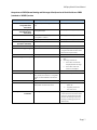
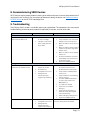
Comparison of SRED (Secure Reading and Exchange of Data) version of Kiosk III with non-SRED
(standard or 'NSRED') version:
Feature
NSRED (Standard)
SRED
02-01 command (non-
encrypted Activate
Transaction)
Supported (unless encryption is turned
on)
Not supported
02-40 command (encryption-
compatible Activate
Transaction)
Supports plaintext output and
encrypted output
Only supports encrypted output
03-00 command
03-00 command not supported if
encryption is enabled
Not supported at any time
03-40 command
Supports plaintext output.
Only supports encrypted output
Encryption Switch
(C7-36/37 commands)
Yes
No
MAC Key
Not supported
Supported
Encryption Type
AES and TDES available
TDES only (SRED uses only TDES to
encrypt transaction sensitive data
to meet PCI requirements)
SAM
Not supported
Supported
Pass-Through Mode Output
Always Plaintext
1. Output plaintext if no sensitive
data.
2. According to white list:
• If the AID is in white list,
output plaintext message.
• If the AID is not in the
white list, no output.
USB
VID: 0x0ACD PID: 0x3710
VID: 0x0ACD PID: 0x3710
Burst Mode Setting
If MSD/EMV encryption is ON and Data
Key exists, then reader is in encryption
mode, and Burst Mode is forced to be
off.
Burst Mode always off.
FW Version
Kiosk III VX.YY.ZZZ
Kiosk III VX.YY.ZZZ.S
Self-Check
Supports self-check when power is on.
No periodic 24-hour self-check
1. Support self-check when
power on.
2. Supports periodic 24-
hour self-check
Tamper Detection and Data
Zeroization
Not supported
Supported. If device is tampered,
reader will erase all sensitive data
and enter deactivated state. (Unit
will then do nothing except keep
beeping and waiting for activate
commands.)

ViVOpay Kiosk III User Manual
Page | 8
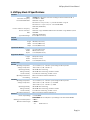
3. ViVOpay Kiosk III Specifications
Hardware
MTBF
500,000 hours based on Telcordia Technologies SR-332 modeled at 40° C.
Transmitter Frequency
13.56 MHz +/- 0.01%
Transmitter Modulation
ISO 14443-2 Type A
Rise/Fall Time: 2-3 µsec. Rise, < 1 µsec fall ISO 14443-2 Type B
Rise/Fall Time: < 2 µsec. each; 8% - 14% ASK ISO 18092
ISO 21481 (PCD & NFC)
Receiver Subcarrier Frequency
847.5 KHz
Receiver Subcarrier
Data
ISO 14443-2 Type A: Modified Manchester ISO 14443-2 Type B: NRZ-L, BPSK
ISO 18092
ISO 21481 (PCD & NFC)
Typical Read Range
0~4 cm (0 to 1.5 inches)
Physical
Controller
Length
105 mm (4.13 inches)
Width
76.2 mm (3.00 inches)
Depth
22.5 mm (0.88 inches)
Square Bezel Antenna
Length
75.1 mm (2.95 inches)
Width
60 mm (2.36 inches)
Depth
17.62 mm (0.69 inches)
Angled Bezel Antenna
Length
96.2 (3.787 inches)
Width
82.3 (3.24 inches)
Depth
17.62 mm (0.69 inches)
Environmental
Antenna
Operating Temperature
-25° C to 70° C (-13° F to 158° F), max change of 10° C per hour
Storage Temperature
-40° C to 85° C (-40° F to 185° F)
Operating Humidity
10% to 90% non-condensing
Storage Humidity
10% to 90% non-condensing, duration 3 months
Transit Humidity
5% to 95% non-condensing, duration 1 week
Operating Environment
Water resistant for indoor and outdoor use
IK /IP Rating
IK 8/ IP 65
Controller
Operating Temperature
-25° C to 70° C (-13° F to 158° F), max change of 10° C per hour
Storage Temperature
-40° C to 85° C (-40° F to 185° F) - nonSRED
-30° C to 85° C (-22° F to 185° F) - SRED
Operating Humidity
10% to 90% non-condensing
Storage Humidity
10% to 90% non-condensing, duration 3 months
Transit Humidity
5% to 95% non-condensing, duration 1 week
Operating Environment
Water resistant for indoor and outdoor use
Electrical
Reader Input Voltage
+7.5V to 30VDC
PLEASE NOTE: For UL compliance. Input voltage needs to be below 30 VDC
Working Current Rated power
Maximum field strength
<500mA
<1000Mw
2.6 dBuA/m at 3 m

ViVOpay Kiosk III User Manual
Page | 9
3.1. Certifications and Approvals
ViVOpay Kiosk III supports the following contactless payment applications and mobile:
• American Express ExpressPay 3.0
• Discover DPAS 1.0
• Interac Flash v1.5
• MasterCard PayPass/MChip 3.0.2
• Visa VCPS 2.1.3 - MSD, qVSDC and IRWIN
• Mifare
• Google Pay, Apple Pay, Samsung Pay & other Mobile Wallets
• Apple Pay VAS & Google Pay Smart Tap Mobile Loyalty Programs

ViVOpay Kiosk III User Manual
Page | 10
4. Kiosk III Installation
Warning: For safety reasons make sure to mount the Kiosk III unit at a height no greater than two
meters from the floor.
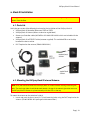
4.1. Parts List
Verify the possession of the following hardware for the installation of the ViVOpay Kiosk III:
• ViVOpay Kiosk III Controller (either non-SRED or SRED)
• ViVOpay Kiosk III Antenna (either standard or angled bezel)
• Antenna to Controller cables (80136204-001 & 80136218-001 which are included with the
antenna)
• ViVOpay Kiosk III to ECR/POS cable (customer supplied). This could be USB or serial cable,
based on the host machine.
• Drill Template for the antenna (PN 80136500-001)
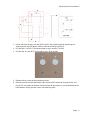
4.2. Mounting the ViVOpay Kiosk III Internal Antenna
Note: Verify the chosen location of the ViVOpay Kiosk III Antenna before marking and drilling the
holes. The two larger holes should be located towards the top of the mounting location to ensure
the ViVOpay Kiosk III Antenna is placed correctly with the LEDs at the top.
To mount the antenna on the exterior of a kiosk:
1. Locate and mark the four 4.4mm (0.173 inch) mounting holes using the Drill Template for the
antenna. (PN 80136500-001 packaged inside antenna box.)

ViVOpay Kiosk III User Manual
Page | 11
2. Locate and mark the two 14.0 mm (0.551 inches) access holes (used for connecting the
antenna power, the LED power, and data cable to the ViVOpay Kiosk III).
3. Drill the four 4.4 mm (0.173) mounting holes using a number 17 drill bit.
4. Drill the two 14.0 mm (0.551 inch) holes using a 35/64 drill bit.
5. Remove the nuts from the four mounting screws.
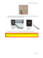
6. Route the end of the cable (80136204-001) with the RJ45 connector through the left 14.0
mm (0.551 inch) hole into the kiosk. Verify the front of the antenna is not upside down on the
kiosk before inserting the four screws into mounting holes.

ViVOpay Kiosk III User Manual
Page | 12
7. Align the four screws with the mounting holes and attach the ViVOpay Kiosk III to the outside
surface. Ensure the cable is not pinched or binding.)
8. Use the four nuts to secure the ViVOpay Kiosk III to the outside surface of the kiosk.
Note: Tighten the nuts securely so the ViVOpay Kiosk III does not move on the outside surface of
the kiosk. If the Angled Bezel Antenna is being installed, tighten the nuts to 5-7 in/lbs. for a good
weather seal.

ViVOpay Kiosk III User Manual
Page | 13
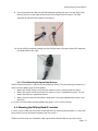
9. Attach the end of the cable with the SMB connector through the right 14.0 mm (0.551 inch)
hole and attach it to the socket on the back of the ViVOpay Kiosk III antenna. The SMB
connector pushes on to the socket on the antenna.
10. Attach the RJ45 connector coming from the ViVOpay Kiosk III Antenna to the RJ45 receptacle
on the 80136204-001 cable.
4.2.1. Flush-Mounting the Square Bezel Antenna
The RF field of the antenna is sensitive to the proximity of metal. To flush mounting the antenna in a
metal surface or bezel, there are three options:
• Mount with the RF emitting surface of the antenna at least 1cm forward of any metal.
• Mount with the RF emitting surface of the antenna at least 1cm behind any metal. This will
reduce the effective range of the antenna.
• Mount flush with the metal but allow a minimum of 1cm spacing between the antenna and
the metal.
In all cases, test the antenna mounting before engaging in a full-scale installation.
4.3. Mounting the ViVOpay Kiosk III Controller
If screws can be visible, use the installer to drill four holes for mounting the controller. (It is advisable
to use security screws to prevent tampering with the screws.)
Otherwise, the installer can use double-sided tape to mount the controller to any clean surface.

ViVOpay Kiosk III User Manual
Page | 14
Note: The ViVOpay Kiosk III Controller must be mounted within 1 meter of the antenna. If the
antenna is mounted of a surface that opens (such as a door) make sure the controller and antenna
are close enough that there is no tension on the cable when the enclosure is open.
4.3.1. Mounting the ViVOpay Kiosk III Controller Using Screws
1. Position the ViVOpay Kiosk III Controller on the interior of the kiosk with enough room for the
antenna mounting surface to be fully opened.
2. Locate the four 4.4mm (0.173 inch) mounting holes by holding the ViVOpay Kiosk III Controller
in position and mark the holes.
3. The following diagram shows the spacing on the holes to be drilled for mounting the ViVOpay
Kiosk III Controller:
4. Drill the four 4.4 mm (0.173) mounting holes using a number 17 drill bit.
5. Use four screws and nuts to mount the ViVOpay Kiosk III Controller to the kiosk surface.
(Mounting screws are not provided and must be supplied by the installer.)
6. Tighten the nuts to hold the ViVOpay Kiosk III Controller in position.

ViVOpay Kiosk III User Manual
Page | 15
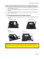
5. Mounting the ViVOpay Kiosk III Controller Using Mounting Tape
1. Position the ViVOpay Kiosk III Controller over the mounting tape and gently apply pressure to
hold the controller in position.
2. Attach the SMB end of the cable (80136204-001) from the antenna to the ViVOpay Kiosk III
controller.
3. Position the ViVOpay Kiosk III Controller over the mounting tape and gently apply pressure to
hold the controller in position.
4.
5.1. Attaching the Cables from the Antenna to Controller
1. Attach the SMB end of the cable (80136204-001) from the antenna to the ViVOpay Kiosk III
controller.
2. Attach the other end of the cable (80136204-001) from the antenna to the ViVOpay Kiosk III
Controller.
Note: Verify that the polarizing lug on the end of the data cable is facing towards the top of the
ViVOpay Kiosk III Controller (away from the mounting plate) before inserting the cable. If the cable
is installed incorrectly (upside down), it will apply the wrong polarity to the LEDs and damage
them.

ViVOpay Kiosk III User Manual
Page | 16
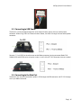
5.2. Connecting to USB Power
The Kiosk III can be powered through the serial communications port or the two-socket power
connector. When using USB Data Communications Power, the Kiosk III though the two-socket power
connector.
Connect +7.5 to 45VDC to the white two-socket Molex connector (mating connector Molex P/N
0039012020 with 5556-series crimps) or to pins 1 and 2 of the RS-232 connector (see next section).
5.3. Connecting to the Data Port
The Kiosk III has two data connections options: USB through the USB connector and RS-232 through
the 14-pin Molex connector.

ViVOpay Kiosk III User Manual
Page | 17
The RS-232 port has the following pinouts:
Pin
Description
Pin
Description
1
Power ground
2
+7.5v to 45VDC
3
Power ground
4
+7.5v to 45VDC
5
No connection
6
Reserved
7
Reserved
8
Reserved
9
Signal ground
10
Signal ground
11
RS-232 Tx
12
RS-232 Rx
13
No connection
14
Reserved
To build the RS-232 cable:
1. Use Molex female connector part number 0511101451 with 50394-series crimps (see
www.molex.com for more information). Pin 1 is indicated by a triangle (diagram is socket-side
view of female connector).
2. Powering the Kiosk III from this connector.
3. Wire the two power pins (pins 2 and 4) together and the two power ground pins together
(pins 1 and 3).
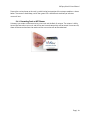
5.4. Make a Purchase with the ViVOpay Kiosk III
The ViVOpay Kiosk III allows for credit and debit card purchases using contactless technology.

ViVOpay Kiosk III User Manual
Page | 18
Present the card or phone so the card is parallel to the front portion of the antenna module as shown
below. The antenna should beep, and all four green LEDs should illuminate briefly to indicate a
successful test.
5.4.1. Presenting Cards or NFC Phones
A dummy transaction can be tested using a test card and the Kiosk III antenna. The antenna's ability
to read the Contactless test cards and test for end-to-end connectivity will be tested. If unsuccessful,
there will be no reaction from the reader and the transaction will not be authorized.

ViVOpay Kiosk III User Manual
Page | 19
6. Installation
The Kiosk III is designed to be mounted on a metal surface, close to any internal motors and electrical
devices that may be operating inside the kiosk. However, the Kiosk III is susceptible to RF and
electromagnetic interference.
Note: It is important that the unit not be mounted near (within 3 or 4 feet) large electric motors,
computer UPS systems, microwave transmitters, anti-theft devices, radio transmitters, and
communications equipment.
The proximity of metal to the RF-emitting end of the antenna can greatly reduce the range of the
antenna.
Precautions for Flush Mounting the Kiosk III Antenna:
1. Label the cable end as host, ViVOpay, and power to simplify connection testing or component
replacement.
2. Tie all cables with nylon cable-ties and route them so that they are inaccessible to customers.
3. Test the Kiosk III installation using a test card to perform an end-to-end transaction. (The
same as an actual purchase on the Kiosk). This transaction should be declined but will prove
absolute connectivity throughout the system.
4. "Requesting Authorization" will display.
5. Each Kiosk III should be tested on a regular basis, either at the start of the day or once per
week, to ensure continued operation and functionality of transactional communications.

ViVOpay Kiosk III User Manual
Page | 20
7. Firmware Upgrade
The Kiosk III can be upgraded using either serial or USB interfaces.
7.1. Preparation
To update the new firmware:
• PC with available serial or USB port
• Kiosk III with a serial data cable or a USB cable attached
• For serial downloads: use cable 220-2492-00, 220-2463-00, and 140-2035-00
• For USB downloads: 220-2492-00, 80097208-001, or for a Mini USB cable and 140-
2035- 00
Firmware files (including Boot Loader files) for the desired firmware.
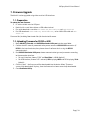
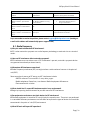
7.2. Uploading Firmware for RS232 or USB
1. Move KIOSKIII_EData.bin and KIOSKIII Bootloader Utility.exe into the same folder.
2. Confirm device is correctly connected to the power source and RS232/USB connection. (If
RS232 is the interface choice, then please close all software that is using the RS232
communication.)
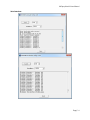
3. Run KIOSKIII Bootloader Utility.exe, choose communication type and parameters according
to the connection interface.
• For serial interface, choose “COM” and Baud Rate is 19200 (default).
• For USB interface, choose “HID” and verify VID displaying 0ACD and PID displaying 3710
(default).
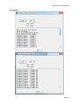
4. Click the “Load” - the firmware will be downloaded into the device. When “Firmware
successfully downloaded” displays, then the firmware has been successfully downloaded.
5. Close Bootloader Utility.
Page is loading ...
Page is loading ...
Page is loading ...
Page is loading ...
Page is loading ...
-
 1
1
-
 2
2
-
 3
3
-
 4
4
-
 5
5
-
 6
6
-
 7
7
-
 8
8
-
 9
9
-
 10
10
-
 11
11
-
 12
12
-
 13
13
-
 14
14
-
 15
15
-
 16
16
-
 17
17
-
 18
18
-
 19
19
-
 20
20
-
 21
21
-
 22
22
-
 23
23
-
 24
24
-
 25
25


IDTECH Kiosk III SRED User manual
- Type
- User manual
- This manual is also suitable for
Ask a question and I''ll find the answer in the document
Finding information in a document is now easier with AI
Related papers
Other documents
-
ID TECH Kiosk IV User manual
-
-
-
 bbpos TB200 Toast Direct Attached User manual
-
bbpos TD200 User manual
-
-
-
-
 Uniform Industrial UIC680FGP Smart Card Reader Operating instructions
-

