Telair Clima e-Van 5400 User manual

Type
User manual

Telair Clima e-Van 5400 is a powerful and versatile air conditioner designed to provide optimal climate control in a variety of settings, including vans, campers, and RVs. With its efficient cooling and heating capabilities, it ensures a comfortable indoor environment even in extreme weather conditions. The device features user-friendly controls and a range of functions to customize your comfort level, making it an ideal choice for those seeking reliable climate control solutions on the go.

Telair Clima e-Van 5400 is a powerful and versatile air conditioner designed to provide optimal climate control in a variety of settings, including vans, campers, and RVs. With its efficient cooling and heating capabilities, it ensures a comfortable indoor environment even in extreme weather conditions. The device features user-friendly controls and a range of functions to customize your comfort level, making it an ideal choice for those seeking reliable climate control solutions on the go.

INSTALLATION GUIDE AND USER
MANUAL
v.001 - December 2020
Clima e-Van 5400H Rev.001
2
The original version of this manual was
written in Italian. The Manufacturer cannot
be held liable for any translation errors in
other language versions.
This manual has been prepared by the
Manufacturer to provide essential information
and instructions in order to perform all
operations for maintenance and use of the air
conditioner correctly and safely.
The manual is an important part of the air
conditioner: it must be stored safely and kept
in good condition throughout the working life
of the machine and protected from
deterioration. It must follow the equipment if
installed on a new vehicle, or if its ownership
changes hands.
The information contained in this manual is
intended for air conditioner installers and all
those involved in its use and maintenance.
The manual defines the purpose for which
the machine is designed and contains all the
information necessary to ensure its safe and
correct use.
Constant observance of the contained
information will ensure user safety, low
running costs and a longer equipment life.
To facilitate reference, this manual has been
divided into chapters specifying the main
notions contained; for quick consultation,
refer to the table of contents.
You are strongly advised to read the manual
and the reference documents throughout: this
is the best way to ensure long-lasting air
conditioner performance, reliability and
prevention of injury or damage.
The drawings included in this manual are
provided for illustrative purposes only. You
may find that the illustrations differ from the
actual parts on the machine in your
possession: this does not in any way affect
the validity of the general and safety
information in this manual.
"Graphic safety symbols" are used in this
document to identify various levels of danger
or important information:
Information to prevent a potentially
dangerous situation that could cause serious
injury or possible damage to health.
Information to prevent a situation that
could potentially cause damage to objects.
Important information for proper
execution of the operations described or for
proper use of the equipment.
Before carrying out any work on
the air conditioner, read this manual
carefully and make sure you have
understood its contents.
Before starting the activity, wear
appropriate personal protective
equipment (goggles, gloves, dust masks,
etc.) for the type of work you are going to
perform.
The air conditioning unit must be
installed exclusively by qualified and
authorised personnel, in accordance with
the instructions provided by the
manufacturer. It must be used on vehicles
or in a stationary installation connected in
all cases to an electrical system installed
in compliance with current regulations
and sized in relation to the electrical
power.
The manufacturer is not liable for
damages resulting from improper use of
the air conditioner.
A double-pole thermal magnetic
circuit breaker must be installed on the
230V power supply line upstream of the
air conditioner to protect against
overcurrents caused by the appliance and
to serve as a disconnect switch when the
appliance is not in use or undergoing
maintenance. The specifications of the
switch should be determined in relation to
the power rating and inrush current of the
air conditioner.
Rev.001 Clima e-Van 5400H
3
Before installation or any
maintenance work involving access to
internal parts of the air conditioner, all the
vehicle's power supplies must be
disconnected (battery or 230V mains
supply).
Failure to follow this instruction can cause
electrical shock to the operator or damage
to the air conditioner or vehicle.
All maintenance work requiring the
air conditioner or diffuser to be opened
must be carried out by qualified
personnel.
When the internal diffuser is removed, the
evaporator fan blades are exposed and
therefore pose a potential risk.
Do not alter or tamper with any part of the
air conditioner.
Do not insert anything into the air vents of
the diffuser or the condenser fan.
In the event of fire, do not open the
top cover of the AC unit and only use
approved fire extinguishers.
Do not attempt to extinguish flames from
the air conditioner with water.
This appliance can be used by
children over 8 years of age or persons
with reduced physical, sensory or mental
capabilities or lack of experience and
knowledge, provided they have been
instructed in the use of the appliance by a
person responsible for their safety.
Children must not play with the appliance.
Cleaning/maintenance operations must
not be performed by children without the
supervision of a person responsible for
their safety.
The information contained in this
publication is accurate at the time of
going to press but may be changed
without notice.
Clima e-Van 5400H Rev.001
4
Via E. Majorana , 49 48022 Lugo (RA) ITALY
“CE” DECLARATION OF CONFORMITY
pursuant to the Machine Directive 2006/42/EC
We hereby declare that the air conditioner, the specifications of which are provided below, is designed and
built to meet the essential safety and health requirements of the European Directive on Machine Safety.
This declaration is rendered null and void in the event of incorrect assembly, improper use or modifications
made to the machine without our written approval.
Machine: AIR CONDITIONER
Model: Clima e-Van 5400H
Serial no. .........................................
Reference Directives:
Machine Directive 2006/42/EC
Low Voltage Directive 2014/35/EU
Electromagnetic Compatibility Directive 2014/30/EU - Regulation 10 UN/ECE Rev. 5
Other harmonized standards applied: EN55014-1; EN55014-2; EN61000-3-2; EN61000-3-3; EN62233;
IEC/EN 60335-1; IEC/EN 60335-2-40; DIN EN 378-2
Technical documentation manager: Raul Fabbri, engineer Raul Fabbri
Lugo, 31/07/2020 THE PRESIDENT
Raul Fabbri
Rev.001 Clima e-Van 5400H
5
CONTENTS
1 GENERAL INFORMATION ........................................................................................................ 6
2 CHARACTERISTICS .................................................................................................................. 6
2.1 Technical Specifications .................................................................................................. 6
2.2 Components .................................................................................................................... 6
2.3 Identification plate ............................................................................................................... 6
3 SHIPPING, HANDLING, STORAGE ........................................................................................... 7
3.1 Storage ............................................................................................................................ 7
3.2 Weight ............................................................................................................................. 7
3.3 Handling .......................................................................................................................... 7
4 INSTALLATION .......................................................................................................................... 7
4.1 Preliminary information .................................................................................................... 7
4.2 Installation solutions ........................................................................................................ 7
4.2.1 Using the existing ventilation hatch ............................................................................ 8
4.2.2 Opening a new hole ................................................................................................... 8
4.2.3 Power Supply Cable .................................................................................................. 9
4.3 Positioning the air conditioning unit ................................................................................. 9
4.4 Connecting the power cable .......................................................................................... 10
4.5 Diffuser installation ........................................................................................................ 10
5 INSTRUCTIONS FOR USE ...................................................................................................... 12
5.1 Foreword ....................................................................................................................... 12
5.2 Preliminary checks ........................................................................................................ 12
5.3 Useful tips...................................................................................................................... 12
5.4 Installing the batteries in the remote control ................................................................... 13
5.5 Information on using the Remote Control ...................................................................... 13
5.6 Remote Control description and functions ..................................................................... 13
5.7 Remote Control Display ................................................................................................. 14
5.8 Diffuser Display ............................................................................................................. 14
5.9 Setting the system time on the remote control ............................................................... 14
5.10 Automatic mode............................................................................................................. 15
5.11 Cool mode ..................................................................................................................... 15
5.12 Warm mode ................................................................................................................... 15
5.13 Timer setting .................................................................................................................. 15
5.14 Operation without the remote control ............................................................................. 16
6 MAINTENANCE ....................................................................................................................... 16
6.1 Cleaning the Filters ........................................................................................................ 16
6.2 Unsatisfactory performance ........................................................................................... 16
6.3 Troubleshooting ............................................................................................................. 17
6.4 Opening the external cover ............................................................................................ 17
6.5 Periodic maintenance .................................................................................................... 17
6.6 Spare parts .................................................................................................................... 18
7 WASTE DISPOSAL .................................................................................................................. 18
8 GENERAL WARRANTY TERMS ............................................................................................. 19
9 WIRING DIAGRAM .................................................................................................................. 20
10 SPARE PARTS LIST .............................................................................................................. 21
Clima e-Van 5400H Rev.001
6
1 GENERAL INFORMATION
The e-Van 5400H air conditioner is designed
for installation on vehicle roofs, although this
does not exclude its use in stationary
applications. It works with a 230 V AC
sinusoidal alternating current power supply.
50 Hz
Using the air conditioner at voltages other
than those indicated could compromise its
efficiency and damage the unit.
As part of its product development and
upgrade policy, the manufacturer reserves
the right to introduce modifications without
prior notice.
2 CHARACTERISTICS
2.1 Technical Specifications
Clima e-Van 5400H
power supply
230 V 50 Hz
sinusoidal
Maximum power rating
3.0 Amp
Inrush current
15 A (0.15 sec.)
Power absorption for cooling
660 Watt
Power absorption for heating
640 Watt
Cooling capacity
5800 Btu/h
Heating capacity
5500 Btu/h
Operating temperature
2÷48 °C
Internal temperature adjustment
16÷31 °C
Internal fan speeds
3
Maximum internal air flow
300 m
3
/h
Type and quantity of coolant gas
R32… 280 g
Protection rating
IP X5
Required generator set
2200 W
Diffuser dimensions (H x L x W)
4.2x45x45 cm
Monobloc dimensions (H x L x W)
23.5x71x62 cm
Weight
30 kg
Some technical specifications in
this table may vary.
The information shown on the air
conditioner ID plate is accurate.
2.2 Components
1 Ventilation grille
2 Upper cover
3 Machine body
4 Technical characteristics sticker
5 Air duct connector for diffuser
6 Diffuser
7 Removable ambient air intake filters
8 Adjustable air outflow vents
9 Courtesy lights
10 Diffuser display
11 Remote control
2.3 Identification plate
1 Model
2 Serial number
3 Type of power supply
4 Electrical power consumption
5 Cooling and heating capacity
6 Type and quantity of coolant gas
7 Coolant gas GWP
6
11
2
1
3
4
5
1
7
7
10
8
8
9
Rev.001 Clima e-Van 5400H
7
8 Maximum circuit pressures
9 Protection rating
10 Weight of air conditioning unit
The nameplate shown here is an
example. The user must take the
specifications given on the air conditioner
nameplate as exact.
3 SHIPPING, HANDLING,
STORAGE
3.1 Storage
During transport the air conditioner is
protected by cardboard packaging. The
conditioner must be stored indoors in a
horizontal position in a dry, ventilated area.
The type of packaging allows up to 5 (five)
conditioners to be stacked on top of each
other.
Do not turn the package upside-
down. The right way up is indicated by the
symbol on the packaging ( ↑↑).
Stacking more than 5 packaged air
conditioners can damage the units and
put personnel at risk of injury.
3.2 Weight
Weight of e-Van 5400H, packaging included:
34 kg
3.3 Handling
Always observe safety and
accident prevention rules when lifting and
handling. Use lifting and handling
equipment with capacity greater than the
load to be lifted.
Packaged air conditioners can be moved
using standard means of lifting and transport.
4 INSTALLATION
4.1 Preliminary information
Improper installation of the air
conditioner can result in irreparable
damage to the appliance and endanger the
user's safety.
If installation of the air conditioner fails to
comply with the instructions in this manual,
the Manufacturer shall not be held liable for
any malfunctioning or safety issues
concerning the air conditioner, pursuant to
Machine Directive 2006/42/EC. Moreover, the
manufacturer shall not be liable for any
resulting injury or damage.
4.2 Installation solutions
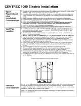
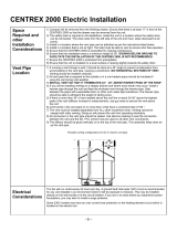
Before climbing on top of the
vehicle check that the roof is strong
enough to be walked on. Check with the
vehicle fitter. If not, a scaffold framework
will be required.
To ensure proper installation of the air
conditioner, it is essential to first check
whether the roof can support its weight; if not,
the roof must be reinforced. Select a central
area of the roof that is sufficiently flat and
horizontal; make sure no obstacles inside the
vehicle can prevent the diffuser from being
1
3
2
4
5
9
10
8
7
6
Clima e-Van 5400H Rev.001
8
fixed in place (Fig. 1 ref. 6) or obstruct the
outflow of refrigerated air from the adjustable
diffuser vents (Fig. 1 ref. 8)
The air conditioner can be installed in one of
two different ways:
by using a ventilation aperture already on
the vehicle (ventilation port)
by opening a new hole.
4.2.1 Using the existing ventilation hatch
This solution can be applied on condition that
the aperture measures 395 x 395 mm (Fig.
2).
Warning: the air conditioner is off-
centre with respect to the 395x395 mm
hole, both longitudinally and transversely;
bear this in mind if there are any other
accessories installed on the camper roof.
Proceed by removing the screws that fix the
port to the roof and then removing the port
itself. Remove the sealant from around the
opening with a scraper (Fig. 3 ref. 1) and
putty screw holes and joints with sealant (Fig.
3 ref. 2)
All waste materials, glue, silicon
and seals must be placed in special
containers and taken to authorised waste
disposal centres.
4.2.2 Opening a new hole
Chose an area on the roof that lies between
two cross members and mark out a 395 mm-
sided square using a felt pen (Fig. 2) and
(Fig. 4 ref. 1); if necessary use the cardboard
template supplied with the air conditioner.
The size of the opening 395 x 395
mm reproduced on the cardboard
template (Fig. 2) is purely indicative.
Before cutting the roof, check the actual
size of the hole with a tape measure.
Using a hacksaw, carefully cut out (Fig. 4 ref.
2) the opening on the roof; be careful not to
cut any electrical wires.
Rev.001 Clima e-Van 5400H
9
If the roof is corrugated, use an adapter
suitable for the corrugation type (not supplied
with the air conditioner); this is applied to the
hole to create a level perimeter on which the
air conditioner seal gasket can rest (Fig. 5).
Make sure the connection between adapter
and camper roof is perfectly sealed; to ensure
a good seal use any gasket supplied with the
adapter or a sealing product.
4.2.3 Power Supply Cable
A 3-core cable with a 1.5 mm
2
cross-section
(live-neutral-earth) must be routed for the
power supply of the air conditioner. The wires
at one end must be connected to the thermal
magnetic circuit breaker (recommended load
10 A) previously installed in the vehicle’s
electrical distribution panel exclusively for the
air conditioner. The other end should reach
the opening made in the roof of the vehicle
and protrude from the hole in the reinforcing
frame by approximately 50 cm in order to
facilitate connection to the air conditioner
(Fig. 6).
The electrical cable must be suitably
protected in order to ensure its integrity and
insulation in all conditions of use of the
vehicle.
4.3 Positioning the air conditioning unit
Before installing, check that the
cylindrical-section gasket on the base of
the air conditioner is still properly
positioned inside the housing on the
frame (Fig. 7 ref. 1).
Apply sealant or putty at the point of contact
between the gasket and the roof (or
corrugated roof adapter). This ensures a
long-lasting, elastic watertight seal. Apply the
recommended amount of product. If an
excessive amount is applied, the bottom of
Clima e-Van 5400H Rev.001
10
the air conditioner might be glued to the roof
of the vehicle, cancelling the damping effect
of the seal, with the resulting propagation of
noise and vibrations. This would also make it
harder to remove the air conditioner, when
needed, with the risk of causing damage to
the underside of the conditioner and the roof.
The arrow in figure 7 indicates the
direction of forward drive.
Lift the air conditioner onto the roof of the
vehicle without dragging it and position it on
the 395x395 mm opening previously
prepared with sealant. To align the air
conditioner on the roof properly, observe -
from inside the camper - the four threaded
inserts for the fixing screws on the bottom of
the air conditioner.
Working from the vehicle interior, shift the air
conditioner until the four inserts are aligned
with respect to the 395x395 mm hole.
Before attaching, check that the cylindrical
seal on the bottom of the air conditioner is still
fitted correctly in its housing.
4.4 Connecting the power cable
Connect the previously prepared cable of the
unit to the 230V AC power supply terminal
(Fig. 9).
Please note that the colour of the wires
according to their use is:
blue wire: neutral
brown wire: live
yellow-green wire: earth connection
Make sure that the power supply cable is not
too long, as it could obstruct the air vents.
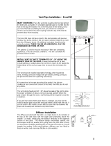
4.5 Diffuser installation
Connect the ribbon cable from the diffuser
display to the connector of the ribbon cable
from the air conditioner circuit board (Fig. 10).
Rev.001 Clima e-Van 5400H
11
Position the diffuser horizontally and place
the rectangular expanded rubber fitting (Fig.
14, ref. 1) over inlet port profile (Fig. 14, ref.
2). If the roof is more than 35 mm thick, a
second fitting will need to be overlapped on
the first one.
The rectangular fitting has an adhesive side
so it can adhere to the diffuser or to the one
below in the case of multiple fittings. The
purpose of the fitting is to form a sealed
channel to connect the diffuser inlet port to
the outlet port on the bottom of the air
conditioner.
Open the two doors on the diffuser that give
access to the fixing screws and air filters.
Using the four M6 screws (supplied), attach
the diffuser to the bottom of the air
conditioner, thus securing it to the roof of the
camper (Fig. 16).
It is important to attach the screws according
to a tightening torque of 1.6 Nm, that is,
0.16 kgm. You are advised to use a torque
wrench.
Incorrect tightening can damage
the support base of the air conditioner,
compromise the seal and cause loud
noise inside the vehicle when the
conditioner is in operation.
Once attachment has been completed, re-
close the doors.
Clima e-Van 5400H Rev.001
12
5 INSTRUCTIONS FOR USE
5.1 Foreword
The power supply voltage must
never be less than 205 V AC, with a stable
frequency of 50 Hz.
Outside the specified operating
temperature range, the efficiency of the air
conditioner is reduced considerably.
The e-Van 5400H air conditioner consists of
nine main parts:
compressor: this circulates the
refrigerating gas inside the system;
condenser: cools the coolant by
changing it from a gaseous to a liquid
state;
evaporator: cooled by the change of
state of the coolant, cools the air passing
through it.
two fans: these move the air through the
condenser and the evaporator;
solenoid valve: switches gas circulation
in order to obtain a cooling or heating
function;
remote control: to program the desired
function
receiver: located in the diffuser, this
receives the remote control signals;
circuit board: receives signals from the
receiver and transforms them into
commands for the various electrical
components of the air conditioner.
The e-Van 5400H air conditioner can provide
cool air in summer and warm air in winter.
If the vehicle has been standing in sunlight a
long time, it is good practice to open doors
and windows to release the accumulated heat
before starting the air conditioner. Once the
temperature inside the vehicle is the same as
the outdoor temperature, close the doors and
windows and start the air conditioning
system; afterwards, avoid opening doors and
windows unless necessary.
5.2 Preliminary checks
Before switching on the air conditioner for the
very first time:
Check that condensate drainage holes
are unobstructed.
Check that the power supply voltage and
frequency match the required
specifications.
Check that air flow through the relative
ducts and vents is unobstructed. To
ensure maximum air conditioner
efficiency, ensure the external ventilation
grilles are unobstructed at all times.
When first switched on using the
remote control, the ventilation and
compressor start up after a few seconds.
After switching off, the compressor will
not restart until at least 3 minutes have
passed.
5.3 Useful tips
Improve the thermal insulation of the
camper by plugging any fissures and
covering glass surfaces with heat-
reflecting curtains.
Avoid frequent opening/closing of
windows unless necessary.
Select a suitable temperature and airflow
rate.
Adjust the outflow vents to maximise
comfort.
Never close both adjustable vents when
the conditioner is running.
Clean the diffuser filters periodically.
Do not obstruct airflow inlets/outlets with
fabric, paper or anything else.
Do not spray water inside the air
conditioner.
Periodically check that the condensate
drain holes are not obstructed.
Periodically check that external intake
grilles are unobstructed to maintain
maximum air conditioner efficiency.
Clean the air conditioner with detergent
solutions only; never use petrol or
solvents.
During winter garaging or long periods
without use, it is recommended that you
disconnect the air conditioner from the
power socket.
Rev.001 Clima e-Van 5400H
13
5.4 Installing the batteries in the remote
control
1. Open the battery
compartment
cover by
pressing the
tab and lifting.
2. Insert two new
LR03 Size AAA
1.5V batteries,
according to
the polarity
indicated.
3. Put the battery
cover back in
place.
5.5 Information on using the Remote
Control
Point the remote control towards the
internal unit of the conditioner.
There must be no obstructions between
the remote control and the internal unit.
Do not drop or throw the remote control.
Do not expose the remote control to direct
sunlight or leave it near heating systems
or other sources of heat.
If you do not intend to use the remote
control for some time, remove the
batteries.
If the signal transmission sound is no
longer audible in the internal unit or the
transmission symbol is no longer clearly
visible on the display screen, the batteries
need replacing.
If the remote control resets when a
control button is pressed, the battery
power is too low and the batteries should
be changed.
5.6 Remote Control description and
functions
1 - Display (for details see Fig. 19)
2 - On/Off to start or stop the air conditioner.
3 - +TEMP and TEMP to set the desired
temperature between 16 and 31 °C.
4 - FAN to select one of three internal fan
speed settings or allow the air conditioner to
select the most appropriate setting.
5 - MODE to select Automatic, Cold or Hot
operating modes.
6 - TORCH, switches on the torch on the front
of the remote control (hold-down operation)
7 - TIMER to activate the timer function and
set the air conditioner start and stop times.
8 - +HOUR and HOUR to adjust the time on
the remote control and the timer function
start/stop times.
9 - CLEAR to delete timer function
programming.
10 - SET to enter time adjustment mode on
the remote control or confirm the timer
function start/stop times.
9
1
2
3
6
4
5
8
7
10
11
12
14
13
Clima e-Van 5400H Rev.001
14
11 KEY/RESET to reset the remote control
completely.
12 RGB COLOR, function currently
unavailable.
13 COLD/HEAT, immediately switches
operating mode from hot to cold and vice
versa.
14 LIGHT ON/OFF, lets the user switch the
courtesy light on the diffuser on/off.
5.7 Remote Control Display
1 Automatic mode
2 Cool operating mode
3 Warm operating mode
4 Ventilation mode
5 Timer: start time (only visible if the timer
has been activated)
6 Timer: stop time (only visible if the timer
has been activated)
7 System time
8 Temperature setting
9 Courtesy light on indicator
10 Fan speed setting indicator (when AUTO
is displayed the speed is automatically
controlled by the air conditioner)
11 Data transmission indicator
5.8 Diffuser Display
The diffuser has a display which also
contains the IR remote control receiver.
When the air conditioner is powered by the
mains but is off, the display shows only room
temperature in the first field (Fig. 20 ref. 1)
When the air conditioner is on, the central
field (Fig. 20 ref. 2) shows the symbols that
describe operating mode:
- Ice crystal = COOL mode
- Sun = WARM mode
- Ice crystal + Sun = AUTOMATIC mode
- Fan = ventilation only mode
The third field (Fig. 20 ref. 3) shows fan
mode.
The two figures in the first field (Fig. 20 ref. 1)
normally indicate the ambient temperature
detected by the air conditioner inside the
camper.
When setting the desired temperature with
the remote control, the two digits show the
set temperature for about 15 seconds; they
then show the temperature in the camper
interior again.
5.9 Setting the system time on the
remote control
After inserting the batteries, set the system
time on the remote control:
1) Press the SET button on the remote
control and hold it down until the system
time digits start flashing.
2) Use the +HOUR and HOUR buttons to
adjust the system time setting.
3) Press the SET button again.
1
2
3
5
6
1
2
3
4
11
7
8
10
9
Rev.001 Clima e-Van 5400H
15
5.10 Automatic mode
1) Press the On/Off button
2) Press the MODE button repeatedly until
the display shows the Automatic mode
symbol
3) Set the desired temperature by pressing
the +TEMP and TEMP buttons.
4) Press the FAN button repeatedly to set
the desired fan speed.
5.11 Cool mode
1) Press the On/Off button
2) Press the MODE button repeatedly until
the display shows the COOL mode
symbol.
3) Set the desired temperature by pressing
the +TEMP and TEMP buttons.
4) Press the FAN button repeatedly to set
the desired fan speed.
5.12 Warm mode
1) Press the On/Off button.
2) Press the MODE button repeatedly until
the display shows the WARM mode
symbol.
3) Set the desired temperature by pressing
the +TEMP and TEMP buttons.
4) Press the FAN button repeatedly to set
the desired fan speed.
If the air conditioner is switched off
and immediately re-started or the
operating mode is changed, a three-
minute interval will elapse before the
compressor resumes operating.
If the air conditioner is turned off in
heating mode, the fan will continue
running for a few minutes to dissipate the
heat accumulated inside the air
conditioner; it will then stop by
automatically.
In cool mode, the speed of the
external condensing fan varies
automatically according to the selected
settings and ambient temperature.
5.13 Timer setting
1) Press the TIMER button on the remote
control: the start time ON indicator is
activated.
2) Use the +HOUR and HOUR buttons to
set the start time.
3) Press the TIMER button again: the stop
time OFF indicator is activated.
4) Use the +HOUR and HOUR buttons to
set the stop time.
5) Press the TIMER button again.
6) When the settings have been made,
press SET.
To delete timer programming, press CLEAR.
Start and stop times can be
programmed in 10-minute intervals.
Starting and stopping occurs with a 10-
minute tolerance in relation to the
programmed time.
Clima e-Van 5400H Rev.001
16
5.14 Operation without the remote control
In the event of loss or failure of the remote
control, you can still use the air conditioner:
switch it on/off by touching the touch-key
(ON-OFF symbol in relief) near the display for
about 5 seconds.
The air conditioner will start in automatic
mode, automatic fan speed, temperature
setting 24 °C.
6 MAINTENANCE
6.1 Cleaning the Filters
To ensure full efficiency of the air conditioner,
clean the diffuser filters by washing them with
a neutral detergent solution; allow them to dry
well before refitting them in their housing.
To remove the filters (Fig. 22, ref.1) open
each diffuser door, and then slide them in the
directions indicated by the arrows to release.
Once maintenance work has been
completed, put the filters back in their seats
and re-fasten them by sliding in the opposite
direction.
6.2 Unsatisfactory performance
In most cases, poor air conditioner
performance is caused by incorrect use
rather than actual malfunctions:
The unit is too small for the volume of air
you wish to condition.
The vehicle is poorly insulated.
The doors are opened too frequently.
There are too many people inside the
vehicle.
The power supply voltage is incorrect.
Rev.001 Clima e-Van 5400H
17
6.3 Troubleshooting
If the air conditioner malfunctions,
before attempting any repairs, first check:
that the power supply voltage is correct
that the intake vents are unobstructed
that air outflow vents are open
A list of common problems is given below,
together with their causes and solutions.
1) The air conditioner does not start:
Check that the remote control batteries
are charged.
Make sure the electrical system is
powered: connect a household appliance
or use a voltmeter.
2) Air outflow is insufficient:
Check that the directional vents are
open;
Check that the diffuser filters are clean.
3) Not working in Cool mode:
Check that the temperature setting is
lower than the ambient temperature.
4) Not working in Warm mode:
Check that the temperature setting is
higher than the ambient temperature.
5) The air conditioner is working
inefficiently:
If the air conditioner is working
inefficiently it is necessary to clean the air
filter, condenser and evaporator using
specific detergents. It is always advisable
to clean the air conditioner when it has
remained idle for a long period.
If the air conditioner does not recover its
initial yield even after the exchangers
have been cleaned, check the
refrigerating gas load.
6.4 Opening the external cover
The external cover, made of ABS plastic, is
attached to the base with 6 re-usable rivets.
To remove them proceed as illustrated in Fig.
26.
Use a flat-head tool to push the core of the
rivet inwards by about 5 mm (p. 1, 2 and 3).
Remove the rivet from its seat (p. 4 and 5).
Before re-using it push the core of the rivet
outwards by about 5 mm (p. 6), then re-insert
it all the way into its seat (p. 7 e 8). Lastly,
press the core of the rivet until it is flush with
the outer body (p. 9).
6.5 Periodic maintenance
Remove the external cover and remove
any leaves or other deposited material.
Clean the heat exchangers (evaporator
and condenser) via the special detergent
and rinse with water. Check that the
condensate drain holes are unobstructed.
Check that the seal gaskets are in good
condition and there is no water infiltration
into the vehicle.
Remove any traces of oxidation from
metallic parts and protect the area with
suitable paint.
Check that wiring insulation is in good
condition and eliminate any traces of
oxidation or moisture.
Check that all screws are properly
tightened.
Clima e-Van 5400H Rev.001
18
6.6 Spare parts
If the event of repair or replacement of parts,
use only original spare parts.
7 WASTE DISPOSAL
The materials used for the construction of this
appliance are recyclable. In the event of
disposal, it is advisable to take the unit to a
specialist workshop or designated waste
collection centre.
All waste materials must be
disposed of properly by taking them to
authorised waste collection centres.
Rev.001 Clima e-Van 5400H
19
8 GENERAL WARRANTY TERMS
TELAIR guarantees its products against any construction material and/or
manufacturing faults and defects.
The right to warranty cover for new products is valid for a period of 24
months from the time of handing over to the end user, or for maximum
1000 operating hours, whichever limit is reached first. In all cases the
warranty period will end no later than 26 months (28 months if delivered
outside of Europe) after ex factory delivery.
For electric and hydraulic components, pipes, belts, sealing elements,
injection nozzles, clutches and drives, the warranty term is 12 months
from the time of handing over to the end user, or maximum 1000
operating hours, whichever limit is reached first. In all cases the
warranty period will end no later than 14 months (16 months if delivered
outside of Europe) after ex factory delivery.
In any case, the costs of lubricants and consumables will be charged.
Any transport expenses will have to be covered by the purchaser; the same
applies to any expenses connected with inspections requested by the
customer and accepted by TELAIR.
The manufacturer’s warranty shall only be valid if:
the customer has carried out routine maintenance according to the
recommended schedule and has promptly visited the nearest after-sale
centre if required.
the customer can produce a document showing the date of sale (invoice or
receipt for tax purposes).
Such document must be kept with care and be intact when shown to the
TELAIR After-Sales centre on requesting service.
In any case, the purchaser shall not be entitled to:
terminate the contract;
makes claims for damages or injuries;
request an extension of the manufacturer’s warranty in the event of
product defects or malfunctions.
Clima e-Van 5400H Rev.001
20
9 WIRING DIAGRAM
CLIMA e
-VAN 5400H
Key
C3 = Evaporator fan c
apacitor
C4 = Condenser fan c
apacitor
C5 = Compressor drive c
apacitor
EvGAS = 4
-way solenoid valve
MC = Compressor motor
VC = Condenser fan motor
VE = Evaporator fan motor
CTP = Condenser temperature sensor
ETP = Evaporator temperature sensor
ITP = Interior temperature sensor
TR = Circuit board power supply transformer
  • Page 1 1
  • Page 2 2
  • Page 3 3
  • Page 4 4
  • Page 5 5
  • Page 6 6
  • Page 7 7
  • Page 8 8
  • Page 9 9
  • Page 10 10
  • Page 11 11
  • Page 12 12
  • Page 13 13
  • Page 14 14
  • Page 15 15
  • Page 16 16
  • Page 17 17
  • Page 18 18
  • Page 19 19
  • Page 20 20
  • Page 21 21
  • Page 22 22
  • Page 23 23
  • Page 24 24
  • Page 25 25
  • Page 26 26
  • Page 27 27
  • Page 28 28

Telair Clima e-Van 5400 User manual

Type
User manual

Telair Clima e-Van 5400 is a powerful and versatile air conditioner designed to provide optimal climate control in a variety of settings, including vans, campers, and RVs. With its efficient cooling and heating capabilities, it ensures a comfortable indoor environment even in extreme weather conditions. The device features user-friendly controls and a range of functions to customize your comfort level, making it an ideal choice for those seeking reliable climate control solutions on the go.

Ask a question and I''ll find the answer in the document

Finding information in a document is now easier with AI