PRESSURE SWITCH
(DUAL SEAL)
MODEL AEF – MBF
Installation, Operation, and Maintenance Manual
Argus Machine Co. Ltd. 5820 – 97 Street, Edmonton, Alberta T6E 3J1
Phone: (780) 434-9451 Fax: (780) 434-9909 www.argusmachine.com
MN-PS-002 July 2015
Printed in Canada
© 2007, Argus Machine Co. Ltd.

PRESSURE SWITCH (DUAL SEAL)
INSTALLATION, OPERATION, AND MAINTENANCE
MN-PS-002
July 2015
Page 1
TABLE OF CONTENTS
1.0 SCOPE ............................................................................................................................................. 2
2.0 GENERAL ........................................................................................................................................ 2
3.0 APPLICABLE STANDARDS .......................................................................................................... 3
4.0 SAFETY ........................................................................................................................................... 3
5.0 HANDLING AND STORAGE .......................................................................................................... 3
5.1 HANDLING .................................................................................................................................. 3
5.2 STORAGE ................................................................................................................................... 3
6.0 INSTALLATION ............................................................................................................................... 4
6.1 GENERAL NOTES ...................................................................................................................... 4
6.2 INSTALLATION INSTRUCTIONS ............................................................................................... 4
7.0 OPERATION .................................................................................................................................... 5
7.1 OPERATING INSTRUCTIONS.................................................................................................... 5
7.2 PRESSURE SETTING ................................................................................................................ 5
7.3 MICROSWITCH REPLACEMENT .............................................................................................. 6
8.0 MAINTENANCE ............................................................................................................................... 6
9.0 TROUBLESHOOTING ..................................................................................................................... 7
10.0 CONTACT INFORMATION ............................................................................................................. 7
ATTACHMENTS:
INSTALLATION AND OPERATION INSTRUCTIONS (TB-PS-001, Page 1) 8
IMPORTANT NOTICE, CAPACITOR DISCHARGE IGNITION (TB-PS-001, Page 2) 9
WIRING INSTRUCTIONS (ARGUS WIRING HARNESS) (TB-PS-002) 10

PRESSURE SWITCH (DUAL SEAL)
INSTALLATION, OPERATION, AND MAINTENANCE
MN-PS-002
July 2015
Page 2
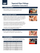
Argus Pressure Switch
(Automatic Reset - Model 'AEF')
Item Description Item Description
1 Cap 6 Adjusting Screw, Leaf Spring
2 Switch Housing 7 Spring Adjustment Nut
3 Main Stem 8 Microswitch
4 Access Collar 9 Leaf Spring
5 Bottom Sub 10 Locking Screw, Switch Block
1.0 SCOPE
Argus Machine Co. Ltd. manufactures pressure switches (automatic or manual reset) used to make or
break an electrical circuit (an electric motor, a gas engine, etc.) upon sensing either ‘high’ or ‘low’ flow line
pressure. This manual details the procedures for installation, operation and maintenance of Argus
Pressure Switch Models ‘AEF’ and ‘MBF’ which are certified and marked for “Dual Seal” applications
(September 2007).
2.0 GENERAL
The Argus Pressure Switch (automatic or manual reset) is designed to make or break an electrical circuit
(an electric motor, a gas engine, etc.) upon sensing either ‘high’ or ‘low’ flow line pressure. Installation,
operation, and maintenance of Argus Pressure Switches shall comply with procedures as described in
this manual. The Argus Pressure Switch (automatic or manual reset) is designed for:
1) Rated Maximum Operating Pressure of 5000 PSI (34,475 kPa).
2) Allowable Temperature Ranges:
a. Ambient: –50 F (-46 C) to +104 F (+40 C)
b. Switch Housing: –50 F (-46 C) to +275 F (+135 C)
c. Continuous Process Media: –50 F (-46 C) to +400 F (+204 C)
d. Intermittent Process Media: +675 F (+357 C) Max.
CAUTION: Remove Pressure Switch from process line if Switch Housing temperature
exceeds +275 F during steaming operations.

PRESSURE SWITCH (DUAL SEAL)
INSTALLATION, OPERATION, AND MAINTENANCE
MN-PS-002
July 2015
Page 3
3) Manufactured for sweet and sour service.
4) Certified by CSA and have the NRTL/C mark signifying that they are suitable for use in Canada and
the United States for Class I, Group D, Hazardous Locations (Division 1 and 2), Dual Seal
5) NEMA 4 and 7 enclosure
3.0 APPLICABLE STANDARDS
Argus Type 'F' Pressure Switches are designed to meet the following standards:
1) ABSA: CRN No. OF2161.2134
2) ASME: B31.3
3) CSA: C22.2 No. 30
4) ANSI/ISA: 12.27.01
5) NACE: MR0175
4.0 SAFETY
Many routine procedures are potentially hazardous if executed incorrectly or in unsafe conditions,
particularly when toxic/flammable product is present. Caution must be exercised when high temperature
and/or pressure exists in the system. Other precautions should be observed are listed below:
1) Disconnect power supply before opening cap.
2) Avoid getting moisture inside cap; keep all electrical components dry.
3) Pressure Switches must meet the service requirements for the application.
4) Always follow government and site safety regulations.
5) Use of appropriate safety equipment and clothing is mandatory. Eye protection should be used when
operating Pressure Switches.
6) Never Strike the Pressure Switch or attached equipment.
7) Do not stand on the Pressure Switch, or use it as a step.
8) Any fittings or accessories must meet the service requirements for the application.
9) Always use Argus O.E.M. parts for service or repair.
5.0 HANDLING AND STORAGE
5.1 HANDLING
1) Care must be taken to prevent the Pressure Switch from being damaged.
5.2 STORAGE
1) Pressure Switches should be stored in a dry environment and should be left in the original packaging
prior to installation.
2) Thread protectors should remain in place until the Pressure Switch is to be installed.

PRESSURE SWITCH (DUAL SEAL)
INSTALLATION, OPERATION, AND MAINTENANCE
MN-PS-002
July 2015
Page 4
6.0 INSTALLATION
6.1 GENERAL NOTES
Argus Pressure Switches may be supplied alone or with a CSA approved Argus Wiring Harness
assembly. (Refer to Argus Pressure Switch brochure for more information).
On request, Argus technicians can attach the Argus Wiring Harness assembly to the Pressure Switch in
the factory. This eliminates the need to remove the Cap when installing an Argus Pressure Switch in the
field.
Argus Pressure Switches are adjusted through a window in the Bottom Sub (it is not necessary to open
the Cap when adjusting the pressure setting), hidden under the Access Collar.
Argus Pressure Switches are normally supplied with a 2" NPT male threaded connection on the Bottom
Sub. Other connections may be available on special request. Ask your Argus representative for special
application connections.
6.2 INSTALLATION INSTRUCTIONS
1) Every Argus Pressure Switch is shipped in its own cardboard packaging carton and contains an
Installation and Operation instruction sheet (Bulletin No. TB-PS-001). Remove this sheet and verify
that the shipment description at the bottom of the page is correct. This contains information regarding
the Pressure Switch Model Number, Serial Number, factory settings and pressure setting range.
Please keep this instruction sheet for future reference.
2) Check female threads in the flow line fitting for any burrs, dirt, debris, or visible signs of damage
before installing the Pressure Switch.
3) Remove thread protectors from the end of the Pressure Switch as well as the 1/2” NPT port (if
applicable).
4) Check all threads for any signs of damage, dirt or debris.
CAUTION: Do not attempt to install the Pressure Switch if there is any evidence of damage
to any threads.
5) If any of the Pressure Switch threads are damaged, return to Argus for repair or replacement.
6) Apply a thin coat of a suitable thread sealant to male threads and hand-tighten bottom connection into
the female flow line fitting.
7) When placing a wrench onto the bottom sub of the Pressure Switch, avoid contact with threads.
CAUTION: Do not wrench on the aluminum access collar.
8) Tighten with wrench until proper make-up is achieved. If make-up is difficult to achieve, remove the
Pressure Switch and check for any foreign matter, thread damage or galling and repeat above
procedure.
9) Check the female (box) threads on the Switch Housing for damage, dirt or debris. In the event of
serious damage please return the Pressure Switch complete with the instruction sheet and packaging
carton to your Argus representative. Do not attempt to install the electrical conduit if there is serious
damage to the female (box) threads on the Switch Housing.
10) Remove the Cap from the Switch Housing (use a screwdriver in the break-out slots provided in the
Cap if necessary).
11) The male (pin) threads on the electrical conduit must be dry (do not use any lubricant, teflon tape or
thread dope). Feed the electrical wires through the port and screw the conduit into the Switch
Housing female (box) port hand-tight only.

PRESSURE SWITCH (DUAL SEAL)
INSTALLATION, OPERATION, AND MAINTENANCE
MN-PS-002
July 2015
Page 5
12) Use a pipe wrench on the electrical conduit to tighten it into the female (box) port until proper make-
up is achieved. If this appears to be difficult to achieve, remove the conduit and check for any foreign
matter, thread damage or galling.
13) Attach electrical wires to the Microswitch as per Argus Wiring Instruction sheet (Bulletin No. TB-PS-
002).
Microswitch Manufacturer's Recommended Torque (Maximum)
Mounting Screws…………………3 in-lbs
Terminal Screws………………… 4 in-lbs
Panel Mount Bushing…………… 4-6 in-lbs
CAUTION: Tightening mounting screws above 3 in-lbs changes operating characteristics
and increases the possibility of cracking the case. Applying excessive torque to
the terminal screws when attaching the wires may cause damage to the
Microswitch.
14) Install the Cap on the Switch Housing and hand-tighten only. When properly installed, the Cap should
meet the shoulder on the Switch Housing. It is not necessary to wrench tighten the Cap to ensure a
seal.
CAUTION: Do not over-tighten the Cap, as damage may occur.
15) Once installation is complete, the Argus Pressure Switch should be operated two (2) or three (3)
times to verify the factory settings.
7.0 OPERATION
7.1 OPERATING INSTRUCTIONS
1) Once installation is complete, the Argus Pressure Switch will trip automatically.
a) If it is an automatic reset switch, it will reset automatically when the pressure returns to within
normal operating range.
b) If it is a manual reset switch, it will reset when the operator pushes the reset button in top of
the switch.
7.2 PRESSURE SETTING
1) Rotate Access Collar counter-clockwise until it hits the upper shoulder of the Switch Housing. This
allows access to the port in the Bottom Sub. The slotted Spring Adjustment Nut should now be
visible.
2) Using a flat blade (Standard) screwdriver, insert the blade into one of the slots and rotate the Spring
Adjustment Nut to either increase or decrease the pressure setting as required. Rotating the Spring
Adjustment Nut clockwise increases the set point, counter-clockwise decreases the set point.
Continue adjusting until the desired set point is achieved. Refer to the Argus Pressure Switch
brochure for the available pressure ranges as per the model number.
3) Rotate the Access Collar clockwise until it hits the lower shoulder of the Bottom Sub. The access port
should now be covered to keep out moisture and debris. (In conditions of severe vibration, the
optional Vibration Lock may be purchased and used. Install the Vibration Lock with the pins in one
slot of the Spring Adjustment Nut prior to screwing the Access Collar down).
CAUTION: Leave the Access Collar in the “down” position after adjustments have been
completed.

PRESSURE SWITCH (DUAL SEAL)
INSTALLATION, OPERATION, AND MAINTENANCE
MN-PS-002
July 2015
Page 6
4) The optional Tamper Seal Block may be purchased and used to prevent anyone from tampering with
the set point once it has been established. To use, simply install the Tamper Seal Block with the
capscrew provided into the hole in the Switch Housing. Run a wire through the holes in both the
Tamper Seal Block and the capscrew and fix with a leaded seal. If the seal is broken, tampering may
have occurred and the set point should be checked.
7.3 MICROSWITCH REPLACEMENT
If the Microswitch should fail during normal operation it can be easily replaced in the field using the
following procedure:
1) Make sure that the power supply to the Pressure Switch is turned off.
2) Remove the Cap from the Switch Housing (use break-out slots in the Cap if required).
3) Disconnect all of the electrical wires from the Microswitch and tuck them out of the way.
4) Using a 3/16" T-Handle hexagonal wrench, loosen and remove the Switch Block Locking Screw.
5) Lift out the entire Microswitch sub-assembly.
6) Place the new Microswitch sub-assembly in the Switch Housing and tighten the Switch Block Locking
Screw with the 3/16" T-Handle hexagonal wrench.
CAUTION: Do not over-tighten, as damage may occur.
7) Re-attach all the electrical wires to the Microswitch as they were before. (Refer to Argus Wiring
Instructions Bulletin No. TB-PS-002).
8) If necessary, make adjustments to the Leaf Spring. Use a flat blade screwdriver to tighten the Leaf
Spring Adjusting Screw clockwise until it shoulders. Turn the Adjusting Screw counter-clockwise
until you hear the Microswitch trip off (approximately 3 turns). Turn the Adjusting Screw 1 1/2 turns
clockwise to set.
9) Install the Cap on the Switch Housing and tighten until the Cap shoulders with the Switch Housing.
10) Turn on the power supply to the Pressure Switch.
8.0 MAINTENANCE
Argus recommends that a preventive maintenance program be implemented to ensure the longevity of
the Argus Pressure Switch.
1) Argus recommends that the operator periodically (quarterly) test each Pressure Switch to ensure that
it is working properly.
2) Tests may consist of a pressure test and verification of unit shutdown.
a) For a Pressure Switch that is set for increasing pressure the operator may close a valve
downstream and check that the Switch trips off at the appropriate set point. If the set point
is incorrect, the operator should adjust it to the original setting. (See 7.2 Pressure Setting).
b) For a Pressure Switch that is set for decreasing pressure the operator may close a valve
upstream and check that the Switch trips off at the appropriate set point. If the set point is
incorrect, the operator should adjust it to the original setting. (See 7.2 Pressure Setting).
c) The Pressure Switch may also be taken off the line and sent to an Argus Service Center for
testing and adjustment.
3) Visually check for excessive moisture in the Bottom Sub, by looking in the Access Port. If excessive
moisture is present the Pressure Switch should be cleaned and serviced by Argus or one of their
approved Service Centers.
4) Argus also recommends that the Pressure Switch be tested after a service rig has done any work on
the well site.
5) The operator should visually check the Pressure Switch for any leaks or physical damage each time
that he/she works on it. The Bottom Sub has two weep holes that will indicate when the internal
gasket or diaphragm has failed. Ensure these weep holes are free of debris or foreign material. If

PRESSURE SWITCH (DUAL SEAL)
INSTALLATION, OPERATION, AND MAINTENANCE
MN-PS-002
July 2015
Page 7
excessive leaking (small amounts of moisture that is trapped inside the Bottom Sub may leak out
normally) is evident the Pressure Switch should be replaced as soon as possible. The Pressure
Switch may then be sent to an Argus Service Center for assessment and/or repair.
6) Argus recommends that due to the sensitivity of the Microswitch the customer should consider
carrying one (1) spare Microswitch sub-assembly in inventory for every ten (10) Pressure Switches in
the field.
9.0 TROUBLESHOOTING
10.0 CONTACT INFORMATION
For Ordering Argus Pressure Switches or for Service please contact us at:
Argus Machine Co. Ltd.
Order Desk (Assembly Division)
5820-97 Street,
Edmonton, Alberta, Canada
T6E 3J1
Toll Free: 1-888-434-9451
Phone: (780) 434-9451
Fax: (780) 434-9909
Problem Possible Causes Possible Solutions
Switch does not trip at
proper pressure, or does
not trip at all
a) Faulty electrical cable or
connections
b) Pressure set point needs
adjustment
c) Microswitch needs to be
recalibrated
d) Microswitch failure
a) Check for damaged cable and/or loose
connections
b) Adjust pressure set point using the Spring
Adjustment Nut, see Section 7.2
c) Adjust switch using the Leaf Spring
Adjusting Screw, see Section 7.3
d) Replace Microswitch, see Section 7.3
Leaking from weep holes
a) Pressure Switch gasket or
diaphragm failure
a) Remove switch from line and send for
servicing
/