Page is loading ...

READ AND SAVE THESE INSTRUCTIONS
DRI-STEEM Models
GTS
®
and GTS-DI
GAS-TO-STEAM HUMIDIFIERS
Installation, Operation
and
Maintenance Manual
For toll-free technical
support call: 1-800-328-4447
This manual must be left with the owner and should be accessible for reference.
WARNING: If the information in this manual
is not followed exactly, a fire or explosion
may result causing property damage,
personal injury, or loss of life.
• Do not store or use gasoline or other flammable vapors and
liquids in the vicinity of this or any other appliance.
WHAT TO DO IF YOU SMELL GAS
• Do not try to light any appliance.
• Do not touch any electrical switch; do not use any
phone in your building.
• Immediately call your gas supplier from an off-site
phone. Follow the gas supplier's instructions.
• If you cannot reach your gas supplier, call the fire
department.
• Installation and service must be performed by a qualified
installer, service agency, or the gas supplier.
GTS-IOM-0900.pdf 1 11/17/2009 3:52:19 PM

2
To the purchaser and the installer
Thank you for purchasing DRI-STEEM Model GTS
®
equipment. We
have designed and built this equipment to give you total satisfaction
and many years of trouble-free service. Proper installation and
operating practices will ensure your achieving that objective. We
therefore urge you to become familiar with the contents of this
manual.
DRI-STEEM Humidifier Company
FOREWORD
GTS-IOM-0900.pdf 2 11/17/2009 3:52:23 PM

3
GTS
®
program code nomenclature ...................................... 4
Models GTS and GTS-DI ...................................................... 5
Safety precautions ................................................................ 6
Specifications and capacities .............................................. 7
Dimensions ........................................................................... 8
Installation
Precautions ................................................................ 9
Required clearances ................................................... 9
Locating the humidifier ................................................ 10
Supply water and drain overflow connections .............. 10
Makeup water piping and material ............................... 11
Drain piping and material............................................. 11
Gas piping guidelines .................................................. 12
Gas leak testing ......................................................... 14
Combustion and ventilation air .................................... 15
Electrical .................................................................... 16
Flue venting guidelines ............................................... 17
Mounting the humidifier
Standard ..................................................................... 19
Indoor enclosure ......................................................... 19
Adjustable leg assembly option .................................. 21
Outdoor enclosure ...................................................... 22
Steam supply connection methods ..................................... 26
Condensate return piping ..................................................... 27
RAPID-SORB
®
assembly and installation
Horizontal duct installation .................................... 27
Vertical duct installation ......................................... 29
ULTRA-SORB
®
installation ................................................... 29
AREA-TYPE application ....................................................... 30
Start-up and operation .......................................................... 31
Start-up/commissioning check sheet .......................... 32
Maintenance
GTS (standard model only) ......................................... 34
GTS-DI model only ..................................................... 34
Both GTS and GTS-DI ................................................ 35
Troubleshooting ................................................................... 36
Replacement parts ................................................................ 50
Caution label ......................................................................... 59
Two-year limited warranty .................................................... 60
TABLE OF CONTENTS
GTS-IOM-0900.pdf 3 11/17/2009 3:52:23 PM

4
GTS
®
PROGRAM CODE NOMENCLATURE
A 14-digit VAPOR-LOGIC
®
3
program code
appears on the front of the control cabinet and on
the wiring diagram inside the control cabinet. The
program code specifies the parameters of the
VAPOR-LOGIC
3
microprocessor, which controls
your humidification system. An explanation of
the program code is detailed below.
VAPOR-LOGIC
3
program code
A. Type of units:
E = English
M = Metric
B. VAPOR-LOGIC
3
system type:
G = GTS
®
S = STS
®
L = LTS
®
V = VAPORSTREAM
®
M = VAPORMIST
®
C = CRU
®
V
U = ULTRA-FOG
®
N = Steam Injection
C. VAPOR-LOGIC
3
board classification:
1 = One-tank system
2 = Two-tank system
3 = Three-tank system
4 = Four-tank system
5 = Five-tank system
6 = Six-tank system
D. Digital display/keypad features:
1 = Single keypad
E. Type of outputs:
0 = Steam valve/100% SSR
1 = One heat stage
2 = Two heat stages
3 = Three heat stages
4 = Four heat stages
F. System pounds output:
##### = Output capacity
(e.g., 00285 = output capacity in lbs/hr)
G. Type of water level control:
D = DI w/ manual drain
E = DI w/ end of season drain
M = Standard w/ manual drain
A = Standard w/ autodrain
H. Operating mode:
1 = Single staged
2 = Externally staged
3 = not used
4 = not used
5 = not used
6 = GTS
7 = TP
8 = SSR
9 = Steam valve
I. VAV options:
V = Option present
O = Option not selected
S = SDU option
J. Temperature compensation options:
T = Option present
O = Option not selected
K. Type of humidity sensing device:
N = None, for on/off
C = 0-135 ohm humidistat
D = 6-9 VDC humidistat
H = 0-10 VDC humidistat
E = 4-20 mA humidistat
X = 4-20 mA transmitter
Q = Dew point transmitter
S = Special
GTS-IOM-0900.pdf 4 11/17/2009 3:52:23 PM

5
GTS
®
AND GTS-DI HUMIDIFIERS
GTS Gas-to-Steam
Humidifier
The GTS is a gas-fired humidifier
that burns either natural or propane
gas to generate steam for humidifica-
tion. The unit has from one to four
burners, which are fired into a heat
exchanger. This heat exchanger is,
in turn, submerged in a tank of water.
When there is a call for humidity, the
burners fire and generate steam until
the call for humidity ends. The GTS
is compatible with DRI-STEEM's
dispersion panels RAPID-SORB
®
and ULTRA-SORB
®
.
The GTS humidifier is designed for
use with all water types. The stan-
dard GTS model supports softened
or unsoftened water and uses a
probe-type level control system to
sense water level. This probe
requires water conductivity of 100
micromhos/cm (about 2 gr/gal)
minimum to function. Therefore, it
will not operate on water treated by
reverse osmosis or deionization.
The GTS-DI model is available for
use with deionized or reverse
osmosis water. This unit produces
chemical-free steam and reliable,
accurate humidification control. It is
virtually maintenance-free, with no
wasted water, heat, or downtime.
The DI unit uses a float valve to
control water levels. The standard
GTS model can be converted in the
field to a GTS-DI.
OM-1084
Drain valve
Gas
valve
Probes or float
Fill valve
Heat exchanger
Evaporating chamber
Cover
Blower
ULTRA-SORB
®
dispersion panel
Cover knob
Control
cabinet
Shroud
Flue box
GTS-IOM-0900.pdf 5 11/17/2009 3:52:23 PM

6
SAFETY PRECAUTIONS
WARNING:
Improper installation, adjustment, alteration, service,
maintenance, or use can cause carbon monoxide poison-
ing, explosion, fire, electrical shock, or other conditions
which may cause personal injury or property damage.
Consult a qualified installer, service agency, local gas
supplier, or your distributor or branch for information or
assistance. The qualified installer or agency must use
only factory authorized and listed kits or accessories
when modifying this product. A failure to follow this
warning can cause electrical shock, fire, personal injury,
or death.
• Inspect humidifier and accessories upon arrival for
damaged, missing, or improper parts. If there is a
problem, call DRI-STEEM.
• Application of this humidifier should have special
attention given to vent sizing and material, gas input
rate, and unit sizing. Improper installation or misappli-
cation of the humidifier can cause excessive servicing
or permanent component failure.
• When working on equipment, observe precautions in
literature, tags, and labels attached to or shipped with
the unit and observe other safety precautions that may
apply. Wear safety glasses and work gloves. Have a
fire extinguisher available during start-up, adjustment
procedures, and service calls.
• Do not use this appliance if any part has been under
water. Immediately call a qualified service technician
to inspect the appliance and to replace any part of the
control system and any gas control that has been under
water.
• Do not lift humidifier by gas controls, gas manifold, fire
box, or control shroud.
• Should overheating occur, or the gas supply fail to shut
off, shut off the manual gas valve to the appliance
before shutting off the electrical supply.
GTS-IOM-0900.pdf 6 11/17/2009 3:52:25 PM

7
SPECIFICATIONS AND CAPACITIES
Specifications, capacities and weights
Capacity notes
• At sea level, approximately 172 BTUs are required to
raise the temperature of one pound of water from 40 to
212 °F. (At sea level, 2257 kJ are required to raise the
temperature of one kilogram of water from 4 to 100 °C.)
• An additional 970 BTUs are required to change the
state of one pound of 212 °F water to vapor. (An
additional 2257 kJ are required to change the state of
one kilogram of 100 ° C water to vapor.)
• Another factor to consider is condensation steam loss
from hoses and tubes. Use the following steam loss
guidelines:
– Vapor hose: 0.15 lbs/ft/hr (0.22 kg/m/h)
– Insulated pipe: 0.05 lbs/ft/hr (0.07 kg/m/h)
– Dispersion tubes: 0.50 lbs/ft/hr (0.7 kg/m/h)
LP gas
All models operate at rated Mbh/kW input.
Connection sizes
* Add 15 full load amps for outdoor enclosure heater load on GTS 100-400.
* Add 20 full load amps for outdoor enclosure heater load on GTS 600-800.
High altitude
A derate in Mbh/kW exists due to high altitude. See the
chart below for high altitude derate information.
edutitlA
%etareD
teeFsreteM
0002-0016-00
0052-1002567-0162
0003-1052519-5674
0053-10035601-5196
0004-10530221-56018
0054
-10040731-022101
0005-10545251-073121
0055-10055761-525141
0006-10550381-576161
0056-10060891-038181
0007-10565312-08
9102
0057-10075822-531222
0008-10570442-582242
Model
number
Steam
capacity per
hour
Input
Steam
outlet
Recommended
vent size
Operating
weight
Shipping
weight
Outdoor
enclosure
operating
weight
Outdoor
enclosure
shipping
weight
115 volt
60 Hz
full load
amps*
lbs kg Mbh kW inches mm lbs kg lbs kg lbs kg lbs kg
GTS-100 75 34 100 29
2" NPT
or 2" hose
(DN50)
5 130 600 275 300 135 1150 520 850 385 1.8
GTS-200 150 68 200 59
2" NPT
or 2" hose
(DN50)
5 130 600 275 300 135 1150 520 850 385 1.8
GTS-300 225 102 300 88
3" flange
(DN80)
7 180 775 350 375 170 1325 600 925 420 3.0
GTS-400 300 136 400 117
3" flange
(DN80)
7 180 775 350 375 170 1325 600 925 420 3.0
GTS-600 450 204 600 176
4" flange
(DN100)
8 205 1000 455 500 225 1750 795 1250 570 4.5
GTS-800 600 272 800 234
4" flange
(DN100)
10 255 1275 580 600 275 2025 920 1325 600 6.0
Description
GTS
100-200
GTS
300-400
GTS-600 GTS-800
Gas
1/2" NPT
(DN15)
1" NPT
(DN25)
1" NPT
(DN25)
1-1/4" NPT
(DN32)
Water makeup (fill)
1/4" NPT
(DN8)
1/4" NPT
(DN8)
1/4" NPT
(DN8)
1/4" NPT
(DN8)
Drain 1" (DN25) 1" (DN25) 1" (DN25) 1" (DN25)
GTS-IOM-0900.pdf 7 11/17/2009 3:52:25 PM

8
DIMENSIONS
Description
GTS-100, GTS-200 GTS-300, GTS-400 GTS-600 GTS-800
inches mm inches mm inches mm inches mm
A Floor stand length 31.85 809 31.85 809 31.85 809 31.85 809
B Overall length 44.50 1130 49.00 1245 49.00 1245 49.00 1245
C Height of evaporating chamber 33.25 845 33.25 845 33.25 845 33.25 845
D
Steam outlet position
9.25 235 12.00 305 17.25 438 20.25 514
E 9.25 235 9.25 235 9.25 235 9.25 235
F Overall width 25.00 635 30.50 775 41.00 1041 47.00 1194
G Height of control cabinet 20.00 508 20.00 508 20.00 508 20.00 508
H Shroud height 32.00 813 32.00 813 32.00 813 32.00 813
J
Flue position
8.50 216 12.00 305 16.63 422 19.63 499
K 5.00 127 5.50 140 5.50 140 6.60 168
L Flue diameter 5.00 127 7.00 178 8.00 203 10.00 254
M Leg height (distance from floor) 13.35 339 13.35 339 13.35 339 13.35 339
N Leg width 18.50 470 24.00 610 34.50 876 40.50 1029
P
Fill valve connection position
3.30 84 3.30 84 6.58 167 6.58 167
Q 1.38 35 1.38 35 1.38 35 1.38 35
R
Condensate return plug position
25.00 635 25.00 635 25.00 635 25.00 635
S 23.00 584 23.00 584 23.00 584 23.00 584
Mechanical dimensions
OM-1078-1
Top view
N
F
D
G
C
M
Front view
K
H
A
S
B
Side view
J
P
L
Q
E
R
OM-1077
OM-1079
GTS-IOM-0900.pdf 8 11/17/2009 3:52:25 PM

9
INSTALLATION
Precautions
• Installation must conform to the requirements of the
authority having jurisdiction or, in the absence of such
requirements, to the National Fuel Gas Code, ANSI
Z223.1 (latest edition). In Canada, the installation of
this unit must comply with local plumbing or waste
water codes and other applicable codes and with the
current code CAN/CGS-B149.1, “Installation Code for
Natural Gas Burning Appliances and Equipment,” or
CAN/CGA-B149.2, “Installation Code for Propane
Burning Applications and Equipment.”
• Do not install in potentially explosive or flammable
atmospheres laden with grain dust, sawdust, or similar
airborne materials.
• Installation of humidifier in high humidity or salt water
atmospheres will cause accelerated corrosion, resulting
in a reduction of the normal life-span of the unit.
• To prevent premature heat exchanger failure, do not
locate any gas-fired unit in areas where chlorinated,
halogenated or acid vapors are present in the atmo-
sphere.
• Locate the humidifier in an area clear of combustible
materials, gasoline, and other flammable vapors and
liquids.
• With the exception of sealed combustion units, do not
locate units in tightly sealed rooms or small compart-
ments without provision for adequate combustion air
and venting. Room air combustion must be supplied
through a minimum of two permanent openings in the
wall, with at least one near the bottom. The openings
should provide one square inch of free area per 1000
BTUH input rating of the unit, with a minimum of 100
square inches for each opening. See the table and
information on Pages 15 and 16 for additional informa-
tion.
• Remove all shipping brackets and materials before
operating the humidifier.
• Humidifier flue gases must be vented to the outside
atmosphere.
• Power supply disconnect switch must be in the off
position while making wiring connections to prevent
electrical shock and equipment damage. All units must
be wired in strict accordance with the wiring diagram
furnished with this unit.
• Turn off all gas while installing the gas piping and
manual shutoff valve for the humidifier.
GTS clearance recommendations
For recommended service and maintenance purposes the
following clearances should be maintained:
• Heat exchanger removal - front, 30" (762 mm)
• Burner shroud removal - front, 30" (762 mm)
• Control cabinet - right side, 36" (914 mm)
• Cover removal - top, 18" (457 mm)
• Distance from bottom of tank to floor, 13.25"
(337 mm) minimum
Cover 18" (457 mm)
Heat exchanger
30" (762 mm)
Control
cabinet
36"
(914 mm)
Burner
shroud
30" (762 mm)
OM-1081
Clearances
GTS-IOM-0900.pdf 9 11/17/2009 3:52:25 PM

10
INSTALLATION
Locating the humidifier
• Provide a level, solid foundation for the humidifier.
Locate the humidifier as near as possible to a chimney
or outside wall so that the flue pipe from the humidifier
is short and direct. The location should also be such
that the gas ignition system components are protected
from water during humidifier operation and service.
• The humidifier should be installed in a location away
from drafts and should be properly protected. If installed
in a separate room, follow the instructions concerning
combustion and ventilation air.
• The humidifier should be located in an area where
leakage from the tank or its connections will not result
in damage to the adjacent structure or to lower floors of
the structure. When such locations cannot be avoided,
it is recommended that a suitable drain pan, adequately
drained, be installed under the humidifier. The pan must
not restrict combustion air flow.
• The humidifier must not be installed on carpeting, tile or
other combustible material other than wood flooring
(indoor application only).
• Install humidifier so that electrical components are
protected from water.
• The appliance must be kept free and clear of insulating
materials when located in an insulated space. Insulating
material may be combustible. Inspection of the appli-
ance area must be performed when the appliance is
installed, or when insulation is added.
Supply water and
drain overflow connections
IMPORTANT: The humidifier is shipped with the auto-
matic drain valve locked in the manual open position.
This position reduces the possibility of the valve seat
becoming damaged from the heat of sweating the drain
connection during installation. After the drain connection
has been completed, the “manual open” lever position
must be reset to the auto position. Failure to close the
drain valve will not allow the tank to fill.
Regardless of the type of water used, the following
general instructions must be followed:
• Union connections must be made at the humidifier on
the cold water supply and drain/overflow lines.
• A shutoff valve should be provided in the supply water
line to isolate the humidifier from the water system
while servicing.
• If the water pressure is above 60 psig (414 kPa) and/or
water hammer would be objectionable, a pressure
reducing valve or shock arrester should be installed.
• A 1" (25 mm) opening is provided in the humidifier tank
to accommodate skim and/or overflow protection.
(Note: Follow local code requirements regarding size of
drain pipe.)
• Insulating unions or bushings must be used to make
connections between copper and other dissimilar metal
fittings, such as galvanized steel. These insulating
fittings are required to minimize electrolytic corrosion,
which results from the direct connection of dissimilar
metals in a water system.
• Before beginning ignition sequence of the humidifier at
a new installation, be sure the humidifier tank is full of
water and the water is free to flow into the tank.
GTS-IOM-0900.pdf 10 11/17/2009 3:52:26 PM

11
INSTALLATION
Makeup water piping and material
Minimum makeup water pressure must be 25 psi
(172 kPa). When nonmetallic water piping is used, it must
be rated to withstand 212 °F (100 °C) or greater tempera-
ture. If not, the final three feet of piping connected to the
humidifier should be metallic and should not be insulated.
As part of the fill valve assembly, the needle valve
restricts the rush of cold water entering the evaporating
chamber during the fill cycle. Adjusting the supply water
OM-737N
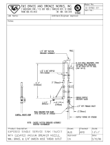
* Drain piping material must be suitable for 212 °F (100 °C) water.
** Refer to local codes for drain pipe sizing and maximum temperature requirements.
DI water
flow with the needle valve will reduce fill cycle noise
generated by collapsing steam in the humidifier. Adjusting
the needle valve will also reduce the drop in output during
a fill cycle. Care must be taken to not reduce the fill rate
below the humidifier's capacity, as this will cause a low-
water shutdown.
Drain piping and material
If nonmetallic pipe or hose is used, it must be capable of
withstanding temperatures up to 212 °F (100 °C).
¼" NPT (DN8) water supply line,
25 psi (172 kPa) minimum
Steam outlet
SST manual
drain valve
Water skim/overflow outlet
Air gap
Open drain**
Shroud
Float-operated low
water cutoff
Float-operated water
makeup valve
Flue connection
Drain piping*
(by installer)
OM-736N
Standard water
¼" NPT (DN8) water supply line,
25 psi (172 kPa) minimum
Steam outlet
Motorized drain valve with manual override
Water skim/overflow outlet
Air gap
Open drain**
Shroud
Three-probe level control
and low water cutoff
Solenoid water
makeup valve
Flue connection
Drain piping* (by installer)
Redundant low water cutoff sensor
Condensate plug
Condensate plug
Redundant low water cutoff sensor
GTS-IOM-0900.pdf 11 11/17/2009 3:52:26 PM

12
INSTALLATION
Gas piping guidelines
CAUTION:
Gas pressure to humidifier controls must never
exceed 24" wc (6 kPa). A 1/8" NPT (DN6) plugged
tapping, accessible for test gauge connection, must
be installed immediately upstream of the gas supply
connection to the appliance.
• After threading and reaming the ends of the pipes,
inspect piping and remove loose dirt and chips.
• Support piping so that no strains are imposed on unit
or controls.
• Use two wrenches when connecting piping to unit
controls.
• Provide a drip pocket before each unit and in the line
where low spots cannot be avoided.
• Takeoff to unit should come from top or side of main to
avoid trapping condensate.
• Piping subject to wide temperature variations should be
insulated.
• Pitch piping up toward unit at least 1/4" (6 mm) per 15'
(4.5 m) of horizontal run.
• Compounds used on threaded joints of gas piping must
be resistant to the harmful action of liquefied petroleum
gases.
• Purge air before lighting unit by disconnecting piping at
gas control. In no case should line be purged into
heat exchanger.
• After installation, check field piping and humidifier gas
train for gas leaks.
• Do not use soap solution or open flame on humidifier
gas train. A gas leak detector is recommended.
• Install a ground joint union and a manual shutoff valve
immediately upstream of the unit including a 1/8" NPT
(DN6) plugged tapping accessible for test gauge
connection. Pressure tappings for test gauges are
located on all gas valves.
• Allow at least 5' (1.5 m) of piping between any high
pressure regulator and unit pipe connection.
• Piping installation must be in accordance with local
codes, and ANSI Z233.1, “National Fuel Gas Code,” or
CAN/CGA-B149 in Canada. Do not use flexible
connectors.
• Piping to units should conform with local and national
requirements for type, volume and gas handled, and for
pressure drop allowed in the line. Refer to the tables on
the next page to determine the gas flow in cubic feet
per hour or m
3
/hr for the type of gas and size of unit to
be installed. Using this value and the length of pipe
necessary, determine the pipe diameter. Where several
units are served by the same main, the total capacity,
gas flow, and length of main must be considered. Avoid
pipe sizes smaller than 1/2" (DN15). The Gas Pipe
Capacities Table on the next page allows for the usual
number of fittings with a 0.3" wc (0.7 kPa) pressure
drop.
• The Specific Gravity Conversion Table should be used
when the specific gravity of the gas is other than .60 for
natural gas or 1.53 for propane. Please refer to the
example on Page 14 for the use of both tables on the
next page.
GTS-IOM-0900.pdf 12 11/17/2009 3:52:26 PM

13
INSTALLATION
Gas piping
OM-1086 * Supplied by others
GTS
®
100-200
To gas valve
To gas valve
OM-1087
Gas supply line
Drip pocket*
Plugged 1/8"
NPT (DN6)
test gauge
connection*
Humidifier
shroud
Gas
cock*
½" NPT (DN15)
tubing
1" NPT
(DN25)
tubing
½" NPT x ½" NPT
x 1" NPT tee (by
DRI-STEEM)
(DN15 x DN15
x DN25 tee)
GTS 300-400
Gas supply line
Drip pocket*
3" (76 mm) min.
Plugged 1/8"
NPT (DN6)
test gauge
connection*
Humidifier
shroud
To gas valve
Gas cock*
½" NPT (DN15)
piping
½" NPT (DN15)
union by
DRI-STEEM
* Supplied by others
* Supplied by others
OM-1087B
GTS-800
OM-1087A
GTS-600 * Supplied by others
To gas
valve
Humidifier
shroud
½" NPT
(DN15)
piping
1" NPT
(DN25)
piping
1" x 1" x 1" NPT tee
(by DRI-STEEM)
(DN25 x DN25
x DN25 tee)
Plugged
1/8" NPT
(DN6)
test gauge
connection*
Drip
pocket*
Gas
cock*
*
To gas
valve
To gas
valve
Gas
supply
line
Humidifier
shroud
½" NPT
(DN6)
piping
1¼" NPT
(DN32)
piping
1¼" x 1¼" x 1¼" NPT tee
(by DRI-STEEM)
(DN32 x DN32
x DN32 tee)
Gas
supply
line
Drip
pocket*
Gas
cock*
To gas
valve
To gas
valve
To gas
valve
To gas
valve
Plugged
1/8" NPT
(DN6)test
gauge
connection*
3" (76 mm) min.
3" (76 mm) min.
3" (76 mm) min.
Gas pipe capacities for
gas pressures of .5 psig or less
Specific gravity
conversion factors
Multiplying factor to be used with
table at left when the specific
gravity of gas is other than 0.60
(natural gas) or 1.53 (propane)
Natural gas
Specific
gravity
Factor
0.55 1.04
0.60 1.00
0.65 0.962
Propane gas
Specific
gravity
Factor
1.50 0.633
1.53 0.626
1.60 0.612
Length
of pipe
Gas flow in piping in cfh and m
3
/hr
at pressure drop of 0.3 inches of water (.07 kPa)
Specific gravity = 0.60
Iron pipe diameter in inches (DN)
1/2" (DN15) 3/4" (DN20) 1" (DN25) 1-1/4" (DN32) 1-1/2" (DN40)
ft m cfh m
3
/hr cfh m
3
/hr cfh m
3
/hr cfh m
3
/hr cfh m
3
/hr
10 3 132 3.7 278 7.9 520 14.7 1050 29.7 1600 45.3
20 6 92 2.6 190 5.4 350 9.9 730 20.7 1100 31.1
30 9 73 2.1 152 4.3 285 8.1 590 16.7 890 25.2
40 12 63 1.8 130 3.7 245 6.9 500 14.2 760 21.5
50 15 56 1.6 115 3.3 215 6.1 440 12.5 670 19.0
Example 60 18 50 1.4 105 3.0 195 5.5
400 11.3 610 17.3
70 21 46 1.3 96 2.7 180 5.1 370 10.5 560 15.9
80 24 43 1.2 90 2.5 170 4.8 350 9.9 530 15.0
90 27 40 1.1 84 2.4 160 4.5 320 9.1 490 13.9
100 30 38 1.1 79 2.2 150 4.2 305 8.6 460 13.0
GTS-IOM-0900.pdf 13 11/17/2009 3:52:26 PM

14
Example
For this example, refer to the tables on the previous page.
To determine gas piping size, begin by calculating the
cubic feet/hour (cfh) or m
3
/hr using the following formula:
Btuh (kW) input
Calorific value of gas
Calorific values are:
Natural gas: 1025 btus/ft
3
(10.6 kW-hr/m
3
)
Propane: 2500 btus/ft
3
(25.9 kW-hr/m
3
)
For example, if you had a GTS-400 operating on natural
gas, you would calculate the cfh or m
3
/hr as follows:
400,000 btuh
1025 btus/ft
3
117.2 kW
10.6 kW-hr/m
3
If you needed to run your gas piping 60 feet (18 m), you
would refer to the Gas Pipe Capacities Table and look
horizontally across the 60 foot (18 m) line until you
located the next highest value above your calculated cfh
or m
3
/hr. In this example, you would be looking for the
next highest value above 390 cfh (11.05 m
3
/hr), which
would be 400 cfh (11.3 m
3
/hr), and would indicate the use
of a 1¼" (DN32) pipe for this application.
Using the same example, if the specific gravity of your
natural gas was .55 (instead of the .60 standard) you
would need to refer to the Specific Gravity Conversion
Table for an adjustment factor. In this case, the factor
would be 1.04, which you would multiply by the 390 cfh
(11.05 m
3
/hr) value. This gives you a new value of
406 cfh (11.49 m
3
/hr) . Referring back to the Gas Pipe
Capacities Table, you will see that for the same 60 foot
(18 m) length, you now would need to use 1½" (DN40)
pipe due to the change in the specific gravity of the gas.
Gas leak testing
• When leak-testing the gas supply piping system, the
humidifier and its gas shutoff valve must be discon-
nected during any pressure in excess of 24" wc
(6 kPa). The humidifier must be isolated from the gas
supply piping system by closing its field-installed
manual shutoff valve during any pressure not equal to
24" wc (6 kPa).
• Check gas supply pressure, with all burners running, at
the inlet pressure tap of the combination gas control
valve. The recommended supply pressure is 7" wc
(1.75 kPa) for natural gas or LP gas. Purging of gas
piping should be performed as described in ANSI
Z223.1 (latest edition) or, in Canada, in CAN/CGA-B149
codes. The minimum supply pressure is 6" wc (1.5
kPa)) for natural gas or LP gas.
= 390 cfh
INSTALLATION
= 11.05 m
3
/hr
Gas piping guidelines
GTS-IOM-0900.pdf 14 11/17/2009 3:52:27 PM

15
INSTALLATION
Sealed combustion
The GTS
®
will support sealed combustion using
4" (DN100) PVC or CPVC piping (see drawings on the
next page). On the GTS-100 and GTS-200, there will be a
single point connection to the blower. On the GTS-300
through GTS-800, there will be a single point connection
to a manifold below the shroud.
When running PVC or CPVC piping for sealed combus-
tion, the maximum allowable distance to the outdoor air
source is 70' (21.3 m) with a 5' (1.5 m) equivalent length
for elbows. The outside air source may be either a final
connection outside the building or a connection to an
outdoor air plenum within the building. When the combus-
tion air origination point is outside the building, the
opening must be covered with a large mesh screen to
prevent the introduction of unwanted materials without
restricting airflow. The air intake point must be located at
least 10' (3 m) from the flue vent on horizontally vented
units.
Note: GTS outdoor enclosures are always provided with a
sealed combustion connection.
Combustion and ventilation air
The GTS supports both room air and sealed combustion.
Requirements and recommendations for each follow.
CAUTION:
Air for combustion must not be contaminated by
halogen compounds, which include fluoride, chlo-
ride, bromide and iodide. These elements are found
in aerosol sprays, detergents, bleaches, cleaning
solvents, salts, air fresheners, and other household
products.
CAUTION:
The operation of exhaust fans, kitchen ventilation
fans, clothes dryers, or fireplaces could create a
negative pressure condition at the humidifier. Makeup
air must be provided for the ventilation devices, in
addition to that required by the humidifier. Units that
may be operated in toxic environments should be
equipped with sealed combustion piping.
Room air combustion
• All fuel burning equipment must be supplied with air for
combustion of the fuel. Sufficient air must be provided
to ensure there will not be a negative pressure in the
equipment room or space.
• Provisions for adequate combustion and ventilation air
must be provided in accordance with Section 5.3, Air
for Combustion and Ventilation, of the National Fuel
Gas Code, ANSI Z223.1-1988, or applicable provisions
of the local building codes. Canadian installations must
be installed in accordance with sections 7.2, 7.3, and
7.4 of the CAN/CGA.B149 Installation Codes, and all
authorities having jurisdiction.
• For proper and safe operation this appliance needs air
for combustion and ventilation. Do not block or obstruct
air openings on the appliance, spaces around the
appliance, or air openings communicating with the
appliance area.
• Do not block the flow of combustion and ventilation air.
To provide for necessary oxygen for proper combustion,
openings must be provided to allow outside air to enter
the space where the heater is located. Enclosed
spaces, such as equipment rooms, must be vented at
the blower for combustion air. The size of air openings
must be based on all gas-burning equipment installed in
the space involved. Four types of locations, and the
requirements of each, are outlined in the table on
Page 16.
GTS-IOM-0900.pdf 15 11/17/2009 3:52:27 PM

16
INSTALLATION
Combustion and ventilation air (cont’d.)
Sealed combustion connection
GTS
one-burner
4" dia. (DN100) PVC or CPVC for
venting combustion air to blower
4" dia. (DN100) PVC or CPVC for
venting combustion air to blower
GTS
two-burner
GTS
three-burner
4" dia. (DN100) PVC or CPVC for
venting combustion air to blower
4" dia. (DN100) PVC or CPVC for
venting combustion air to blower
GTS
four-burner
GTS 100-200
GTS 300-400
GTS-600
GTS-800
OM-1097, OM-1097A, OM-1097B
Location of humidifier and required air openings
* Note:The minimum dimension of any opening is 3" by 3"
(76 mm x 76 mm).
Location description Required air opening
Confined space with all
air from inside the
building; conventional
frame, brick or stone
construction with normal
infiltration (Note: This
location rarely provides
enough air for higher
capacity units.)
Two openings, 1 sq. in.
(6.5 cm
2
) per opening
per 1000 BTU/hr
(293 W) input*
The minimum free
area of all openings
combined is 100 square
inches (645 cm
2
)
Confined space with all
air from outside the
building through air
ducts
Two openings, 2 ducts,
1 sq. in. (6.5 cm
2
) per
opening per 2000
BTU/hr (586 W) input*
Confined space with all
air from outside the
building from through-
wall openings only (no
ducts)
Two openings, 1 sq. in.
(6.5 cm
2
) per opening
per 4000 BTU/hr
(1172 W) input*
Unconfined space with
all air from outside the
building
Same as confined
space; all air from
outside the building
Electrical connections
CAUTION:
Do not connect aluminum wire between disconnect
switch and humidifier. Use only copper wire.
WARNING:
The cabinet must have an uninterrupted or unbroken
ground according to National Electrical Code, ANSI/NFPA
70 and Canadian Electrical Code, CSA C22.1, or accord-
ing to local codes, to minimize personal injury if an
electrical fault should occur. This ground may consist of
electrical wire or conduit approved for electrical ground
when installed in accordance with existing electrical
codes. Do not use gas piping as an electrical ground.
• GTS
®
humidifiers must be supplied with 120-volt AC,
60-Hz, separately fused electrical service. The GTS
humidifier is equipped with a transformer to step down
the voltage to 24 VAC control voltage.
• When installed, the GTS humidifier must be electrically
grounded in accordance with local codes or, in the
absence of local codes, in accordance with the National
Electrical Code ANSI/NFPA No. 70-1987. The electrical
conductors shall be Type MTW (105 °C) AWG #14 wire
for line voltage (120V), with BLACK WIRE for HOT,
WHITE WIRE for NEUTRAL, GREEN AND YELLOW
WIRE for GROUND, and #18 gauge for control wiring.
All electrical components and wiring must be protected
from mechanical damage and water. The control
system requires an earth ground for proper operation.
• The humidifier is adjusted for correct performance. Do
not alter throttle setting or restrict venturi opening.
• The electric current characteristics and capacity
requirements should be checked against the nameplate.
All wiring must be in accordance with all governing
codes and with the GTS wiring diagram located inside
the control cabinet. See the table on Page 7 for infor-
mation on the various models.
• Refer to the VAPOR-LOGIC
®
3
Installation and Operation
Manual for additional information on the controller
furnished with this GTS humidifier.
GTS-IOM-0900.pdf 16 11/17/2009 3:52:27 PM

17
INSTALLATION
• If this humidifier is connected to a lined, masonry
chimney, the chimney must be sized and installed
according to the provisions of the National Fuel Gas
Code or Canadian CAN/CGA.B149 requirements.
• Insulation must be added to any roof or wall penetration
vent connector that will be exposed to ambient tem-
peratures of 30 °F (0 °C) or less, especially any appli-
cation using single-wall vent pipe as a connector.
• Do not insulate vent pipe exposed to outdoor weather
conditions (e.g., above roof lines).
• Installation of the vent pipe should be as direct as
possible, with a minimum number of turns or elbows.
• Rigidly support the vent pipe every 5' (1.5 m) or less
with hangers or straps to ensure that there will be no
movement after installation. The humidifier vent box
should not be supporting the weight of the vent piping.
• No portion of the vent system shall extend into, or pass
through, any circulation air duct or plenum.
• The vent system must terminate above the roof surface
per the National Fuel Gas Code or CAN/CGA.B149
requirements, and must include a UL or CUL listed vent
cap or roof assembly, unless prohibited by local codes.
• This humidifier may be commonly vented with other
listed gas-fired appliances. Total input rates of all
appliances will determine the vent size.
• All vent pipe passing through floors, ceilings, and walls
must be installed with the proper clearances from
combustible material, and be fire-stopped according to
the National Fuel Gas Code requirements and Canadian
Standards CAN/CGA.B149.
• In replacement installation, where an existing vent
system may be used, the vent system must be in-
spected for condition, size, type of vent material, and
height to meet the requirements in these instructions.
When connecting the humidifier to a gas vent or
chimney, the installations must be in accordance with
Part 7, Venting of Equipment, of the National Fuel Gas
Code, ANSI Z223.1, or Section 7, Venting Systems and
Air Supply Appliances, of the CAN/CGA B149 Installa-
tion Codes, the local building codes, and the vent
manufacturer's instructions.
• For all applications, the horizontal length of the
vent and vent connector must not exceed the height
of the vent system.
Vertical and horizontal venting guidelines
(stack connection)
• The GTS
®
is a Fan Assisted Category II Appliance.
• Maximum flue temperature is 390 °F (217 °C) + ambient.
• Vent piping must be UL or UL/CSA listed type B, B-W,
B-H, or L.
• Drip tee or flue box condensate port should be used for
flue condensate removal.
• The purpose of venting the gas humidifier is to com-
pletely remove all products of combustion and ventila-
tion gases to the outside air.
• When connecting the humidifier to a gas vent or
chimney, the installation must be in accordance with
Part 7, Venting of Equipment, of the National Fuel Gas
Code, ANSI Z223.1, or Section 7, Venting Systems and
Air Supply Appliances, of the CAN/CGA B149 Installa-
tion Codes, the local building codes, and the vent
manufacturer's instructions.
• Do not reduce the vent diameter, and avoid short turns
in the vent piping. Use the same size stack as the vent
furnished with the humidifier. Maintain a minimum
upward slope of ¼" per linear foot (2%) on all horizontal
runs. Maintain proper support of vent connections and
joints. Observe clearances (in accordance with appli-
cable codes) from all combustible materials, and obtain
an approved cap for the stack outlet. The bottom of the
cap must be one stack diameter above the top of the
stack.
• Inspect for proper and tight construction. Any restric-
tions or obstructions must be removed. An existing
chimney may require cleaning.
• Chimney or vent must extend at least 3' (1 m) above its
passage through a roof and at least 2' (.6 m) above any
ridge within 10' (3 m) of the chimney (local codes
apply).
• This humidifier must not be connected to a chimney
flue servicing a separate appliance designed to burn
solid fuel.
• Never connect this humidifier to a chimney serving a
fireplace, unless the fireplace opening is permanently
sealed off.
• Venting into an unlined masonry or concrete chimney is
prohibited by code.
GTS-IOM-0900.pdf 17 11/17/2009 3:52:27 PM

18
INSTALLATION
Note: Refer to power venter manual for clearance
requirements relative to combustion air openings.
"x"
Power
venter
Barometric
draft control
GTS
humidifier
"x"
Air
intake
3½' (1067 mm) min.
Vent
hood
GTS
®
venting
Recommended value for
"x" approximately 12"
(305 mm)
Air
intake
Recommended value
for "x" approximately 12"
(305 mm)
Equipment required for horizontal venting
OM-1085
metI
004-001STG
slortnocdleif
rebmunledom
008-006STG
slortnocdleif
rebmunledom
retnevrewoP006-OVP0021-EVP
cirte
moraB
repmad
)"5(1-GM)"8(1-GM
doohtneV)"5(5-1-HWS8-HWS
Special horizontal venting requirements
• Distances from the vent terminal to adjacent public
walkways, buildings, and openable windows and
building openings must be consistent with the National
Fuel Gas Code, ANSI Z223.1, and/or CAN/CGA B149
Installation Codes.
• In areas accessible to the public, the vent terminal shall
be at least 7' (2.1 m) above ground level to prevent
burns from the hot terminal surface.
• The vent terminal and air intake locations must be at
sufficient height above ground level to prevent blocking
by expected snowfall.
• Building materials must be protected from degradation
by flue gases.
• A minimum horizontal clearance of 4' (1.22 m) from
electric meters, gas meters, regulators, and relief
equipment must be maintained.
• Maximum equivalent length of vent pipe is 100' (30 m).
Minimum equivalent length of vent pipe is 10' (3 m).
Subtract 5' (1.5 m) equivalent length per elbow.
• Vent box pressure must be -0.01" wc (-2.5 Pa). Set by
adjusting power venter and barometric damper, with all
burners running.
GTS-IOM-0900.pdf 18 11/17/2009 3:52:27 PM

19
MOUNTING THE HUMIDIFIER
The GTS ships with support legs for floor stand mounting.
For proper operation of the electrode-probe, water-level
control and the skimmer system, the humidifier must be
mounted level left to right and front to rear.
A keypad with standard 5' (1.5 m) cable ships loose with
GTS units. A phone jack mounting plate is available for
mounting the keypad on the control cabinet.
Flue
2 mounting
holes per leg
requiring
1/4" x 20 bolts
Support legs
Floor stand mounting
OM-1078
Note: See Page 20 for more drawings of the indoor
enclosure.
The GTS
®
indoor enclosure is shipped with the GTS unit
factory mounted within the cover. A keypad with standard
5' (1.5 m) cable ships mounted to the subpanel in the
GTS indoor enclosure. The unit must only be moved into
place by lifting the unit from under its base frame. The
indoor enclosure may be mounted as is, or it may be
mounted on an optional adjustable leg assembly (see
adjustable leg assembly instructions on the next page).
All necessary plumbing and electrical wires are to be run
under the enclosure and into the appropriate access
locations. There are two clearly marked removable
access doors. One of them, on the front of the unit, is to
gain access to the water fill connection, drain connection,
gas connection, and the flue box outlet. The other, on the
side of the unit, is to gain access to the electrical sub-
panel, cleanout plate, and the steam outlet connection.
The top of the indoor enclosure consists of two pieces,
which are removable. These two pieces may be removed
to gain further access to the flue box connection, steam
outlet connection, and the inspection cover. The two
pieces are removed by backing off the sheet metal
screws, which secure it to the sides of the enclosure. To
reduce the risk of damage to the enclosure, reattach the
two pieces whenever the unit is in operation or when the
unit is being moved.
Indoor enclosure mounting option
6" (152 mm)
legs
Optional
leg
assembly
OM-3000
GTS-IOM-0900.pdf 19 11/17/2009 3:52:27 PM

20
Indoor enclosure mounting (cont’d.)
The optional adjustable leg assembly, if ordered, will be
packaged separately from the GTS indoor enclosure. The
legs will raise the base of the unit off the floor from 15" to
24" (380 mm to 610 mm). To ease installation, the leg
assembly should be assembled and the height adjusted
prior to mounting the unit on the legs. Hand tighten all
nuts and bolts. Do not make any electrical, gas or
plumbing connections to the unit, nor fill the tank, prior to
setting it on the legs. Place the leg assembly on a solid
level surface where the unit is to be mounted, and place
the unit on the leg assembly. Once the unit has been
placed on the legs, square and level the assembly and
then tighten the nuts and bolts securely. Never move the
leg assembly with the unit mounted on it.
MOUNTING THE HUMIDIFIER
Top view indoor enclosure
OM-3001
Steam
outlet
Flue
outlet
A*
* For GTS 100-400, A = 31" (787 mm).
For GTS 600-800, A = 47.5" (1207 mm).
Side view indoor enclosure
Control panel
access door
47.00"
(1194 mm)
OM-3003
Front view indoor enclosure
Adjustable legs*
15"-24"
(381-610 mm)
Burner
and
piping
access
door
36.38"
(924 mm)
OM-3002
* Standard legs fit within the optional leg assembly,
and so the maximum leg height is 24" (610 mm).
GTS-IOM-0900.pdf 20 11/17/2009 3:52:27 PM
/