Page is loading ...

In-Line Railing Installation Instructions
PRE-ASSEMBLED ALUMINUM RAILING
INSTALLATION INSTRUCTIONS
Items and Tools Needed
Posts Installation
Prior to construction:
• Check with your local regulatory agency for special code
requirements in your area. Common railing height is 36" or 42".
Read instructions completely to get an understanding of how the
product goes together and how each piece affects the other.
• Determine the number of railing posts needed for your deck.
Post spacing is 6' or 8' on-center. Example: A 12' x 16' deck
attached to a building with a 4' access opening on one side will
need a total of eight posts. To minimize cutting, use as many full
panels as possible.
Step 1: Install posts by attaching the aluminum base to the surface
of the deck. Position the post so the fastener will go into the floor
joist, and make sure the decking is firmly attached to the joist at
the location of the posts. Proper structural blocking/framing under
the decking material is required when attaching the post to a wood
frame deck because decking alone is not approved as structural
framing (fig. 2).
Step 2: Position the post assembly onto the location where it will
attach to the deck. Four 3/8" diameter mounting holes are provided
on the base. When the final position is determined, mark the base
hole locations. Remove the post assembly and drill 15/64" holes
in the marked locations through the decking and into structural
blocking (fig. 3).
Step 3: Reposition the post assembly over the predrilled holes
and insert the fasteners (NOT INCLUDED). Secure the base
to the deck structure. Make certain the posts are plumb. Note:
Recommend 5/16” x 4” or longer lag screws. If the post requires
adjustment, use shims to level post. If the post requires adjustment,
use shims to level post.
Step 4: Finish by sliding a post base trim (optional) over each post
for a finished look (fig. 4).
Post Base
Trim
Pre-Assembled Panel
Post Cap
39-in
Post
Bracket
Rail
Support
fig. 2
Parts included
Tools required
(1) Pre-assembled panel (4) Rail support connectors for 6ft
(2) Rail supports for 6ft (6) Rail support connectors for 8ft
(3) Rail supports for 8ft (4) Brackets with hardware
(Posts and stair rail kits sold separately)
• Drill/power screwdriver
• Miter or circular saw
with carbide tip blade
• Marked speed square
• Carpenter’s level
• Carpenter’s pencil
• Adjustable wrench
or socket wrench
for bolts, etc.
• Safety glasses/
goggles
• Rubber mallet
• Tape measure
• Lag screws
fig. 1
fig. 4
(1) Pre-assembled Panel (2 or 3) Rail Supports (4 or 6) Rail Support Connectors (2) Top Rail Brackets (2) Bottom Rail Brackets (12) Metal Screws (4) Large Screws (4) Small Screws
fig. 3

Railing Installation
Prior to construction:
• Check building code requirements for maximum spacing
between deck surface and bottom of rail (sweep). Spacing of 3” is
recommended for 36” or 42” finished rail height.
Step 1: Measure the distance between installed posts to determine
the length of the top and bottom rails. Position rail adjacent to
installed posts. The distance between the post and the first
baluster should be less than 4” and equal on both ends. Mark the
length on top and bottom rails.
Step 2: Remove an additional 1/2” on both ends (1” overall) for the
bracket to fit between the rail and post. Trim the top and bottom
rails to length (fig. 5).
Step 3: Place the brackets on ends of the rails. Attach the brackets
to the rails with a screw attached through back of bracket into each
internal screw boss (fig. 6).
Step 4: Prop rail in place and mark the bracket holes on both
posts. Remove rail. Predrill screw locations through the posts,
using a 3/16” drill bit at top bracket locations and 9/64” drill bit at
lower bracket locations.
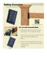
Step 5: A rail support is needed every 2 feet (2 are included in
the 6ft kit, 3 in the 8ft kit). Attach rail support connectors to the
bottom of the lower rail at 2-foot intervals. Predrill using a 1/8” drill
bit. Attach the rail supports to the support block connectors. Mark
the location of the rail support on the deck surface and attach the
other rail support connector to the deck using the included screw
(fig. 7). Drill two ¼” drain holes through the bottom of the rail
to prevent trapping water. Center drain holes between two
baluster locations as baluster can block the pathway and
stop water from properly draining.
Step 6: Attach the rail supports to the support block connectors.
Mark the location of the rail support on the deck surface and attach
the other rail support connector to the deck using the included
screw (fig. 8).
Step 7: Position the rail between the posts. Check for level end-to-
end and vertically. Attach brackets to the post at one end. Repeat
for the other end. Note: Use a driver extension bit to avoid marring
the rail with the drill chuck (fig. 9).
Step 8: Set post caps on each post. Gently tap with rubber mallet
to secure.
Subtract 0.5”
Distance between posts
Subtract 0.5”
fig. 5
fig. 6
fig. 9
fig. 7
fig. 8
•
1/4" Drain Hole

Stair Railing Installation Instructions
Prior to construction:
• Ensure post location is compatible with railing, prior to securing
to the deck, place both posts in position, and lay the bottom rail
along the stair nosing from top to bottom adjacent to both posts.
On the rail side of the post, measure up from the top of the rail
and ensure there is a minimum of 34” to the top of the post. Post
location may need to be adjusted to ensure minimum is obtained.
Repeat this step for the bottom post.
• For a wood deck, position the post so the fasteners will go into
the joists, and make sure the decking is firmly attached to the joists
at the location of the posts. Proper structural blocking/framing
under the decking material is required when attaching the post
to a wood frame deck because decking alone is not approved as
structural framing.
Step 1: Begin by determining where the top and bottom post will
be located. Mark the desired location of the post.
Step 2: Four 3/8” diameter mounting holes are provided on the
base. When final position is determined, mark hole locations and
remove the post assembly. Drill the marked locations through
decking and into structural blocking.
Step 3: Reposition the post assembly over predrilled holes. Insert
fasteners (NOT INCLUDED), then secure the base to the deck
structure. Make certain the posts are plumb. If the post requires
adjustment, add stainless steel washers under the base plate.
Step 4: Finish by sliding a post base trim (optional) over each post
sleeve for a finished look. Note: Installing the post base trim prior
to installing the railing is recommended. However, the two-piece
design does allow the installer to add the post base trim after the
rail has been installed.
Step 5: Measure the distance between installed posts to
determine the length of the top and bottom rails. Position the railing
on the stairs on top of a spacer block along the stair nosings.
Ensure the balusters are plumb. The distance between the post
Post
Cap
Post
Sleeve
Post
Sleeve
Mark Rail for Length
Top and
Bottom Rail
Mark Rail
for Length
Distance Between Posts
Drill 1/4" Drain Hole Through Bottom
Top Rail Bracket
Bottom Rail Bracket
Bottom Rail
Rail Support
Post
Base
Trim
Post
Cap
Top Rail
Equal spacing
on both ends
6'' Max.
•
•
•
•
•
39-in Post
•
•
•
•
•
•
48-in Post
•
Drill ¼'' Drain Hole
Through Bottom
fig. 11
fig. 12
THE DIAGRAMS AND INSTRUCTIONS IN THIS BROCHURE ARE FOR ILLUSTRATION PURPOSES ONLY AND ARE NOT MEANT TO REPLACE A LICENSED PROFESSIONAL. ANY CONSTRUCTION OR USE OF THE PRODUCT MUST BE IN ACCORDANCE WITH ALL LOCAL ZONING AND/OR BUILDING
CODES. THE CONSUMER ASSUMES ALL RISKS AND LIABILITY ASSOCIATED WITH THE CONSTRUCTION OR USE OF THIS PRODUCT. THE CONSUMER OR CONTRACTOR SHOULD TAKE ALL NECESSARY STEPS TO ENSURE THE SAFETY OF EVERYONE INVOLVED IN THE PROJECT, INCLUDING,
BUT NOT LIMITED TO, WEARING THE APPROPRIATE SAFETY EQUIPMENT. EXCEPT AS CONTAINED IN THE WRITTEN LIMITED WARRANTY, THE WARRANTOR DOES NOT PROVIDE ANY OTHER WARRANTY, EITHER EXPRESS OR IMPLIED, AND SHALL NOT BE LIABLE FOR ANY DAMAGES,
INCLUDING CONSEQUENTIAL DAMAGES.
©2020 UFP Retail Solutions, LLC. Deckorators is a registered trademark of UFP Industries, LLC. in the U.S. All rights reserved.
68956 U.S. Highway 131, White Pigeon, MI 49099
10374 4/20
www.lowes.com
and the first baluster should be less than 4” and equal on both ends. Once the railing is in position, clamp the railing to the posts.
Step 6: Temporarily assemble the swivel brackets. Position the swivel bracket in location and mark the rail and post. Repeat for other
end of railing. Note: The distance from the end of the top rail to the first stair baluster will be 1-1/16” longer than the bottom rail to ensure the
balusters are plumb. Add 3/4” to the marked location on the railing and cut to length.
Step 7: Mark locations of the bracket screw holes on the rails. Remove brackets. Predrill through the rail only, using a 9/64” drill bit. Attach the
front end of bracket to rails.
Step 8: Mark location of the bracket base screw holes on the post. Include the bracket side cover when determining the center location.
Predrill through the post, using a 9/64” drill bit. Position the base of each bracket with the bracket cover side facing the stairs, and attach to
the post with two screws.
Step 9: A rail support is needed every 2 feet (2 are included in the 6ft rail kit, 3 in the 8ft kit). Attach rail support connectors to the
bottom of the lower rail at 2-foot intervals using included screws. Predrill using a 1/8” drill bit. Mark the location of the rail support on the step
tread and attach the other rail support connectors to the step tread (fig. 11). Drill one ¼” drain hole through the bottom of the rail to
prevent trapping water. Position the hole toward the lower end of the rail, roughly 1.5” from rail end to avoid the lower bracket.
Step 10: Install the bottom railing between the posts by sliding the brackets together. Attach the side of the bracket with the barrel bolt to
secure in place.
Step 11: Set post caps on each post. Gently tap with rubber mallet to secure.
/